1
Configuration for Communication
INAT Echochange Gateway between AllenBradley EtherNet/IP Networks and SIMATIC
Industrial Ethernet Networks
Configuration
Warranty, Liability and Support
Echochange-Gateway
Copyright © Siemens AG 2009 All rights reserved
23901499_Echochange-Gateway_DOKU_V10_e.doc
Note
Entry-ID: 23901499
The Application Examples are not binding and do not claim to be
complete regarding the circuits shown, equipping and any eventuality.
The Application Examples do not represent customer-specific solutions.
They are only intended to provide support for typical applications. You
are responsible for ensuring that the described products are correctly
used. These Application Examples do not relieve you of the responsibility
to use sound practices in application, installation, operation and
maintenance. In using these Application Examples, you recognize that
Siemens cannot be made liable for any damage/claims beyond the
liability clause described. We reserve the right to make changes to these
Application Examples at any time without prior notice. If there are any
deviations between the recommendations provided in these Application
Examples and other Siemens publications – e.g. catalogs – the contents
of the other documents have priority.
Warranty, Liability and Support
We accept no liability for information contained in this document.
Any claims against us - based on whatever legal reason - resulting from the
use of the examples, information, programs, engineering and performance
data etc., described in this application example shall be excluded. Such an
exclusion shall not apply in the case of mandatory liability, e.g. under the
German Product Liability Act ("Produkthaftungsgesetz"), in case of intent,
gross negligence, or injury of life, body or health, guarantee for the quality
of a product, fraudulent concealment of a deficiency or breach of a
condition which goes to the root of the contract ("Wesentliche
Vertragspflichten"). However, claims arising from a breach of a condition
which goes to the root of the contract shall be limited to the foreseeable
damage which is intrinsic to the contract, unless caused by intent or gross
negligence or based on mandatory liability for injury of life, body or health.
The above provisions do not imply a change in the burden of proof to your
detriment.
Copyright© 2009 Siemens A&D. It is not permissible to transfer or
copy these Application Examples or excerpts of them without having
prior authorization from Siemens A&D in writing.
For questions about this document please use the following e-mail address:
mailto:[email protected]
1.1
Ausgabe 23.02.2009
2/32
Foreword
Echochange-Gateway
Entry-ID: 23901499
Foreword
Objective of the application
Worldwide, the demand for the connection of networks of different
providers increases. Interoperability is of utmost importance because of
economic and technological reasons.
In this context, the products by Allen Bradley/Rockwell are of special
interest. Together with a large number of partner companies, Allen-Bradley
offers a large portfolio of controllers, peripheral devices and network
components especially occupying a remarkable share of the US market.
Copyright © Siemens AG 2009 All rights reserved
23901499_Echochange-Gateway_DOKU_V10_e.doc
The present application exemplary presents how to connect Allen-Bradley
"EtherNet/IP" networks to SIMATIC-supported Ethernet networks. Here, an
"Echochange" module by the INAT company is used.
Main contents of this application
Due to the wide variety of the product ranges by both Allen-Bradley and
Siemens, it is not possible to explain all possible combinations within the
framework of only one application. Therefore, the main focus of the present
document is the application of INAT "Echochange" modules.
Delimitation
This application contains no further description concerning
•
programming principles of Allen-Bradley controllers
•
Allen-Bradley networks.
Additional information
The present selection aid is intended to be a supplement to the application
"Communication with Allen-Bradley ControlLogix Controllers via
PROFIBUS Scanners" (entry ID 23809864, see \3\). Using an
"Echochange" module is an alternative to the network connection
presented there.
The entry no. 23809864 contains essential background information on
Allen-Bradley controllers and network technology. It is recommended to
read the entry mentioned above.
1.1
Ausgabe 23.02.2009
3/32
Foreword
Echochange-Gateway
Entry-ID: 23901499
Structure of the document
The documentation of this application is divided into the following main
parts:
Copyright © Siemens AG 2009 All rights reserved
23901499_Echochange-Gateway_DOKU_V10_e.doc
Part
Description
Application Description
Provides a general overview of the contents. You
will learn about the standard hardware and
software components used.
Function Principles and
Program Structures
This part describes the detailed function processes
of the involved hardware and software components,
the solution structures and – where useful – the
specific implementation of this application. This part
is necessary if you want to learn about the
interaction of the solution components, for example
in order to use them as the basis for own
development.
Structure, Configuration
and Operation of the
Application
This part leads you step by step through the
structure, important configuration steps,
commissioning and operation of the application.
Appendix
This section of the documentation includes further
information, e.g. literature, glossary etc.
Reference to Automation and Drives Service & Support
This entry originates from the Internet application portal of the Automation
& Drives Service and Support. Clicking the link below directly displays the
download page of this document.
http://support.automation.siemens.com/WW/view/en/23901499
1.1
Ausgabe 23.02.2009
4/32
Foreword
Echochange-Gateway
Entry-ID: 23901499
Table of Contents
Table of Contents ......................................................................................................... 5
Automation Task ........................................................................................ 6
2
Automation Solution.................................................................................. 8
3
Functional Mechanisms of the "Echochange" Gateway ...................... 15
4
Function Mechanisms of this Application ............................................. 19
5
Installation and Commissioning............................................................. 21
6
Configuration............................................................................................ 23
7
Bibliography ............................................................................................. 31
Copyright © Siemens AG 2009 All rights reserved
23901499_Echochange-Gateway_DOKU_V10_e.doc
1
1.1
Ausgabe 23.02.2009
5/32
Application Description
Automation Task
Echochange-Gateway
Entry ID: 23901499
Application Description
Content
Here, you will get an overview of Allen-Bradley components and
technologies as well as of possible connections to SIMATIC networks. The
main focus is the connection of SIMATIC-supported Ethernet to EtherNet/IP
(Allen-Bradley).
1
Automation Task
Here you will find information on …
Copyright © Siemens AG 2009 All rights reserved
23901499_Echochange-Gateway_DOKU_V10_e.doc
... which classes of controllers and networks are offered by Allen-Bradley
and which problems might occur during their connection to SIMATIC
networks.
1.1
Overview
Note
In legal terms, "Allen-Bradley" is a subsidiary company of "Rockwell
Automation" dealing with the development and application of
programmable logic controllers.
In order to avoid confusion, in this application the term "Allen-Bradley"
stands for all products offered by Rockwell and Allen-Bradley.
Introduction
Especially in the United States, Allen-Bradley currently occupies a
remarkable market share. To serve for the combination of different
networks and for the increasingly required interoperability, this application
exemplarily presents a possibility of operating an "ISO on TCP" network
with SIMATIC network nodes together with an Allen-Bradley EtherNet/IP
network.
Allen-Bradley controllers and networks
In the course of time, Allen-Bradley developed a series of different
controller classes (PLC 5, SLC 500, ControlLogix etc.) and network types
(DH+, DH 485, ControlNet, EtherNet/IP etc.) which are very different with
regard to their area of application. For this reason, it is impossible to
present a universally applicable solution for connecting SIMATIC products
to Allen-Bradley products. Each case has to be considered separately.
You will find a detailed description of Allen-Bradley's product range under
\3\.
Our example presents the use of a ControlLogix controller combined with
an EtherNet/IP network on the Allen-Bradley side.
1.1
Ausgabe 23.02.2009
6/32
Application Description
Automation Task
Echochange-Gateway
Entry ID: 23901499
Overview of the automation task
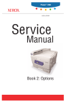
The figure below provides an overview of the automation task.
Figure 1-1
“SIMATIC“
“Allen-Bradley“
ControlLogix
CPU
…
EthernetIP-Bridge
S7-300 CP 343
IO
CPU Ethernet
…
EtherNet/IP
INAT
Echochange
Gateway
Copyright © Siemens AG 2009 All rights reserved
23901499_Echochange-Gateway_DOKU_V10_e.doc
Periphery
Industrial
Ethernet
Periphery
The task is to establish communication between an Allen-Bradley
ControlLogix controller in an EtherNet/IP network on one side and a S7-300
CPU in an Industrial Ethernet network on the other side.
Description of the automation task
Industrial Ethernet and EtherNet/IP are two Ethernet variants which are
supported by both Siemens and Allen-Bradley for sophisticated
communication tasks in industry environment.
Both protocols are similar to each other, but not completely compatible. In
order to establish a connection between two subnetworks, a gateway is
required.
Such a gateway is offered by the INAT company (\5\) and is called
"Echochange" gateway (\6\).
1.1
Ausgabe 23.02.2009
7/32
Application Description
Automation Solution
Echochange-Gateway
2
Entry ID: 23901499
Automation Solution
Here you will find information on …
the solution selected for the automation task.
2.1
Overview of the overall solution
Diagram
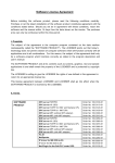
The following Figure 2-1 schematically shows the major components of the
solution.
An "Echochange" gateway is positioned at the interface between an
EtherNet/IP network in which a ControlLogix CPU by Allen-Bradley is
communicating and an Industrial Ethernet network. There, it ensures
communication between the two networks.
Copyright © Siemens AG 2009 All rights reserved
23901499_Echochange-Gateway_DOKU_V10_e.doc
Note
Please observe that the "Echochange" gateway can take over numerous
communication tasks. The solution presented here only gives an example
for a possible use. You will find detailed information on the different
options of the "Echochange" under \6\ and in the device manuals.
In the presented case of application, an Industrial Ethernet branch is
operated with a S7-300 CPU which accesses the network via a CP 343
communication module.
Note
The application example described in "TCP/IP Coupling between an
Allen-Bradley ControlLogix CPU and a S7-400 CPU"
("\download\infos\echochange\examples\clx_s7400.pdf" on the INAT
Echochange installation CD) and serving as our basis provides the use of
a S7-400 CPU on the SIMATIC side. Nevertheless, it is possible without
any major modifications to use a S7-300 CPU instead for the example.
The present instructions are limited to the use of a S7-300 CPU.
A second network branch consists of a ControlLogix CPU accessing an
EtherNet/IP network by means of an EtherNet/IP communications bridge.
Both CPUs are able to communicate on their respective branches with
further nodes (CPUs or I/O devices).
The connection between the two subnetworks is established by means of
an "Echochange" gateway compiling the two protocols in use by adapting
the datagram headers.
In the present application example, this connection is used to exchange
data blocks or variable arrays between the two controllers. Thus, it is
possible to write directly into memory areas of the partner CPU.
1.1
Ausgabe 23.02.2009
8/32
Application Description
Automation Solution
Echochange-Gateway
Entry ID: 23901499
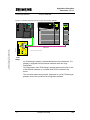
Figure 2-1: Exemplary hardware setup for using an "Echochange" gateway
DC 24 V
PS 307
5A
CPU315-2 DP
SF
ATF
DC5V
FR CE
R UN
STOP
VOLTAGE
S ELE CTOR
S M374
IN/OUT 16
CP 343
SIEMENS
Logix 5500
SF
POWER
LINK
R X/TX
R UN
S TOP
EtherNET/IP
Link
I/O
RS232
BAT
RUN
R UN
STOP
MR ES
OK
REM
LINK NET
PROG
OK
Allen-Bradley
…
SIMATIC NET
x 2
3 4
x 2
3 4
RUN
x 2
3 4
Industrial Ethernet
Copyright © Siemens AG 2009 All rights reserved
23901499_Echochange-Gateway_DOKU_V10_e.doc
Compact Flash *)
echo change
COM
TP 1
TP 2
Net Conn
TX Net 1
RX Net 1
TX Net 2
RX Net 2
Param
Power
Power 24V DC
Ethernet/IP
Reset
*) Compact Flash-Slot derzeit ohne Funktion
INAT
Setup
An "Echochange" gateway is inserted between the two subnetworks. The
gateway is equipped with two Ethernet interfaces which are freely
configurable.
The configuration of the "Echochange" gateway itself can be made via one
of the Ethernet interfaces or via a third serial RS 232 interface at the
device.
The connection parameters (protocol, addresses etc.) of the "Echochange"
gateway can be set by means of the configuration software.
1.1
Ausgabe 23.02.2009
9/32
Application Description
Automation Solution
Echochange-Gateway
2.2
Entry ID: 23901499
Description of the Core Functionality
If the example configuration is used as described here, a cyclic data
exchange between the two CPUs takes place.
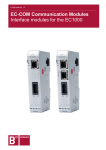
Overview and description of the user interface
For configuring the "Echochange" gateway, a proprietary configuration
software is enclosed in the delivery.
Copyright © Siemens AG 2009 All rights reserved
23901499_Echochange-Gateway_DOKU_V10_e.doc
Figure 2-2: Dialog of the configuration software for the "Echochange" gateway
The CPUs (SIMATIC or ControlLogix) are configured by means of the usual
software packages (SIMATIC Manager or RSLogix).
Process sequence of the core functionality
The "Echochange" gateway can be used for various cross-network
services.
If the example configuration "TCP/IP Coupling between an Allen-Bradley
ControlLogix CPU and a S7-400 CPU"
("\download\infos\echochange\examples\clx_s7400.pdf" on the INAT
Echochange installation CD) enclosed in the scope of delivery of the
installation CD is used, the data exchange takes place between a variable
or a variable field of the Allen-Bradley controller and a data block of the S7
controller. With their data areas, both controllers write into the area of the
respective communication partner.
1.1
Ausgabe 23.02.2009
10/32
Application Description
Automation Solution
Echochange-Gateway
Entry ID: 23901499
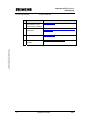
Table 2-1: Overview of the data areas exchanged in the example configuration
Transmitter
Start address / Range
Receiver
Target address
ControlLogix
Data word 0
10 words (INT)
"INT_ARRAY“
S7-300
DB5, DW2
S7-300
DB6, byte 12
16 bytes
ControlLogix
"INT_ARRAY“
Advantages of this solution
Copyright © Siemens AG 2009 All rights reserved
23901499_Echochange-Gateway_DOKU_V10_e.doc
Using the "Echochange" gateway as gateway between the two network
sections offers the following major advantages:
1.1
•
low hardware and wiring effort,
•
manageable configuration effort,
•
high-performance, robust and flexible connection.
Ausgabe 23.02.2009
11/32
Application Description
Automation Solution
Echochange-Gateway
2.3
Entry ID: 23901499
Required Hardware and Software Components
Note
In the following tables, components which are not offered by Siemens are
grayed. For procurement of these components, the indicated distribution
sources are responsible (also see page 13).
Hardware components
Table 2-2: Required hardware components
Copyright © Siemens AG 2009 All rights reserved
23901499_Echochange-Gateway_DOKU_V10_e.doc
Component
No.
MLFB / Order number
Note
SIMATIC Field PG M
Standard
1
6ES7712-0AA0.-0XXX
or comparable PC
with MPI interface
PS 307 power supply
1
6ES7307-1BA00-0AA0
or comparable
power source
SIMATIC S7-300 CPU
315-2DP
1
6ES7315-2AG10-0AB0
or S7-400
Ethernet
communications
processor CP343-1
Lean
1
6GK7343-1EX20-0XE0
or comparable
module
Power supply
1
1756-PA72/B
Procurement via 1
ControlLogix 5500 CPU
1
1756-L1M2
Procurement via 1
1756-ENET EtherNet/IP
interface
1
1756-IB16D
Procurement via 1
"Echochange" Ethernet
gateway
1
200-6000-01
Procurement via 2
Standard software components
Table 2-3: Required software components
1.1
Component
No.
MLFB / Order number
Simatic S7, Step 7 V5.4
(or higher)
1
6ES7810-4CC08-0YA5
RSLogix 5000 Standard
Edition, V13.03 (or
higher)
1
9324-RLD300DEE
Installation and example
software for the
"Echochange" gateway
1
Ausgabe 23.02.2009
Note
German version,
procurement via 1
enclosed in the
scope of delivery
of the gateway,
otherwise
procurement via 2
12/32
Application Description
Automation Solution
Echochange-Gateway
Entry ID: 23901499
Sources of supply for Germany:
Copyright © Siemens AG 2009 All rights reserved
23901499_Echochange-Gateway_DOKU_V10_e.doc
1. Rockwell Automation Zweigniederlassung der Rockwell Int'l GmbH
Düsselbergerstrasse 15
42781 Gruiten
Germany
Phone: +49 2104 9600
Fax: +49 2104 960 121
(also see \7\, \8\)
2. INAT GmbH
Ostendstraße 50A
90482 Nürnberg
Germany
Phone: +49 911 544 27-0
Fax: +49 911 544 27-27
(also see \5\)
Example files and projects
No prepared projects is enclosed in the delivery of this selection aid.
Please fall back on the configurations on the "Echochange" installation CD.
1.1
Ausgabe 23.02.2009
13/32
Application Description
Automation Solution
Echochange-Gateway
2.4
Entry ID: 23901499
Alternative Solutions
The "Echochange" installation CD offers further configuration examples.
Further possibilities of connecting Allen-Bradley controllers to SIMATIC
CPUs:
Using a PROFIBUS scanner made by SST which integrates the CPU as
master device into a SIMATIC PROFIBUS installation. See \3\.
•
Using an Anybus gateway by means of which a SIMATIC CPU can
communicate as master device of a DeviceNet with DeviceNet I/O
devices.
(http://support.automation.siemens.com/WW/view/en/23902276
(starting in fall 2006), starting in fall 2006).
Copyright © Siemens AG 2009 All rights reserved
23901499_Echochange-Gateway_DOKU_V10_e.doc
•
1.1
Ausgabe 23.02.2009
14/32
Function Principles and Program Structures
Functional Mechanisms of the "Echochange" Gateway
Echochange-Gateway
Entry ID: 23901499
Function Principles and Program Structures
Content
This part discusses the detailed function processes of the involved
hardware and software components, the solution structures, and where
sensible the concrete implementation of this application.
You only need this part, if you want to learn about the interaction of the
solution components.
3
Functional Mechanisms of the "Echochange" Gateway
Here you will find information on …
Copyright © Siemens AG 2009 All rights reserved
23901499_Echochange-Gateway_DOKU_V10_e.doc
... how the "Echochange" gateway converts the different protocols.
3.1
Basics of the Gateway Function
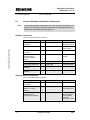
The "Echochange" gateway supports the following protocols:
Table 3-1
Protocol
TCP
UDP
IP
ISO (H1)
ISO on TCP (RFC 1006)
SPS Header
EtherNet/IP (optional)
The gateway can establish the connection between networks operating
several of these protocols.
The OSI reference model ("7 layers")
The OSI reference model provides a structure which serves as standard for
the setup of data transmission protocols. During this setup, different
protocol functions (transmission of individual bits, integrity check of entire
messages, consistency check of a data session etc.) are allocated to
several protocol layers.
1.1
Ausgabe 23.02.2009
15/32
Function Principles and Program Structures
Functional Mechanisms of the "Echochange" Gateway
Echochange-Gateway
Entry ID: 23901499
Figure 3-1
Application layer
Application
oriented
Display layer
Control layer
Transport layer
Transport
oriented
Network layer
Safety layer
Bit transmission layer
Physical Medium
Copyright © Siemens AG 2009 All rights reserved
23901499_Echochange-Gateway_DOKU_V10_e.doc
The "bottom" layers of the OSI model take over the most primitive tasks
(voltage level, timing of the bit-by-bit data transmission). The higher the
layer, the more complex are the tasks.
Data transmission by means of the layer model
By the "top" application, the data are handed over to the physical level step
by step, are transmitted and are reassembled at the receiver.
Figure 3-2
Application
Application
Application layer
Application layer
Display layer
Display layer
Control layer
Control layer
Transport layer
Transport layer
Network layer
Network layer
Safety layer
Safety layer
Bit transmission layer
Bit transmission layer
Receiver
Sender
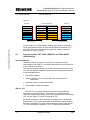
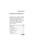
"Echochange" as gateway between different protocols
If there are different protocols between transmitter and receiver, the
"Echochange" gateway acts as a mediator by receiving the message of the
transmitter, by splitting it according to the rules of the transmitter protocol
and by then forwarding it:
1.1
Ausgabe 23.02.2009
16/32
Function Principles and Program Structures
Functional Mechanisms of the "Echochange" Gateway
Echochange-Gateway
Entry ID: 23901499
Figure 3-3
Echochange-Gateway
Application
Application layer
Application layer
Application layer
Application layer
Display layer
Display layer
Display layer
Display layer
Control layer
Control layer
Control layer
Control layer
Transport layer
Transport layer
Transport layer
Transport layer
Network layer
Network layer
Network layer
Network layer
Safety layer
Safety layer
Safety layer
Safety layer
Bit transmission layer
Bit transmission layer
Bit transmission layer
Bit transmission layer
Receiver/Protocol “B“
Sender/Protocol “A“
Copyright © Siemens AG 2009 All rights reserved
23901499_Echochange-Gateway_DOKU_V10_e.doc
Application
For this purpose, the "Echochange" gateway is provided not only with a
serial configuration interface, but also with two Ethernet interfaces "TP1"
and "TP2" which are connected to the respective networks under the
transmitter or receiver protocol.
3.2
Protocol Variants "RFC 1006" (SIMATIC) and "EtherNet/IP"
(Allen-Bradley)
Industrial Ethernet
"Industrial Ethernet" is used as a general term combining several
technologies of the SIMATIC environment which allow the use of Ethernet
in the industrial environment.
This not only comprises specific connections and devices (switches, hubs
etc.), but also protocol adaptations which meet the following requirements
of industrial applications:
•
high system stability,
•
reliable operation even in environments with strong electronic
interference,
•
guarantee of short communication times,
•
high reliability of data transmission
ISO–on–TCP
ISO-on-TCP is a communication protocol which is used within the
framework of Industrial Ethernet. Technically, it is a communications
connection of the transport layer (level 4 of the communication according to
ISO, also see Figure 3-1) which is mapped on TCP.
By means of an ISO-on-TCP connection, messages can be exchanged
bidirectionally. TCP provides a data flow communication without blocking
the data in messages. In contrast, ISO is message-oriented. With ISO-onTCP, this mechanism is mapped on TCP. This process is described in
1.1
Ausgabe 23.02.2009
17/32
Function Principles and Program Structures
Functional Mechanisms of the "Echochange" Gateway
Echochange-Gateway
Entry ID: 23901499
RFC1006 (see below). ISO–on–TCP connections allow program-controlled/
event-controlled communication via Ethernet from SIMATIC S7 to:
•
SIMATIC S7 with Ethernet CP
•
SIMATIC S5 with Ethernet CP
•
PC/PG with Ethernet CP
•
any other system
"RFC 1006"
In principle, TCP is a data flow-oriented protocol. This means that though it
is guaranteed that the data are transmitted completely and arrive at the
receiver in the same sequence as they were send by the transmitter, it is
not guaranteed that the data blocks keep their structure.
Copyright © Siemens AG 2009 All rights reserved
23901499_Echochange-Gateway_DOKU_V10_e.doc
In other words: During transport, restructuring of the data, combination or
splitting might occur:
Figure 3-4
Sender:
A B C
Receiver:
A B
D E F G
C D E
H
F G H I
I J K L M
J K L M
Expanding the TXP protocol by "RFC 1006" is a possibility of making sure
that not only the integrity and sequence, but also the block structure of data
transmission is maintained.
This is important for the so-called message-oriented "H1" services by
means of which the Siemens PLC communication takes place.
EtherNet/IP
EtherNet/IP is an open industrial network standard using CIP ("Control and
Information Protocol") as application protocol. Within the Allen-Bradley
environment, CIP is also used for the ControlNet and DeviceNet protocols.
With EtherNet/IP, data are exchanged either via I/O connections ("implicit
messages") or via Message Connections ("explicit messages").
3.3
Limitation of Possible Data Types
Currently, the "Echochange" gateway only can exchange data of the type
"integer" (two bytes).
1.1
Ausgabe 23.02.2009
18/32
Function Principles and Program Structures
Function Mechanisms of this Application
Echochange-Gateway
4
Entry ID: 23901499
Function Mechanisms of this Application
Here you will find information on …
... which measures have to be taken for configuring the "Echochange"
gateway in order to establish connection between the network parts.
Asymmetric procedure
Due to the protocols in use, the steps to be carried out to use the gateway
are not completely symmetric. In particular, no parameterization of the
ControlLogix CPU has to be performed if this CPU is used as receiver (see
chapter 4.2). In this case, the gateway directly writes into the address of the
respective variables of the Allen-Bradley CPU.
Copyright © Siemens AG 2009 All rights reserved
23901499_Echochange-Gateway_DOKU_V10_e.doc
Note
4.1
Refer to chapter 6 for details on the configuration.
You will find detailed background information on the settings to be done
in the "Echochange" User Manual, manual version 0304-001 (German,
"\download\handbuch\echan_d.pdf" on the INAT Echochange installation
CD) and under "TCP/IP Coupling between an Allen-Bradley ControlLogix
CPU and a S7-400 CPU"
("\download\infos\echochange\examples\clx_s7400.pdf" on the INAT
Echochange installation CD).
Functionality "ControlLogix transmits, SIMATIC receives"
See also chapter 6.1.
The following steps have to be performed to allow a communication from
the ControlLogix to the S7 device:
4.2
•
The ControlLogix device has to transmit the respective data via a "CIP
MSG" command.
•
The "Echochange" gateway receives the data, converts them and
forwards them to the S7 CPU.
•
By means of an "AG_RECV“ block, the S7-300 CPU receives the data
which are transmitted via the connection established by means of
the gateway.
Functionality "SIMATIC transmits, ControlLogix receives"
See also chapter 6.2.
The communication from the S7 to the ControlLogix CPU is established as
follows:
•
1.1
By means of an "AG_SEND“ block, the S7-300 transmits the relevant
data to the "Echochange" gateway.
Ausgabe 23.02.2009
19/32
Function Principles and Program Structures
Function Mechanisms of this Application
Echochange-Gateway
•
Entry ID: 23901499
The gateway directly forwards the data to the ControlLogix CPU.
Copyright © Siemens AG 2009 All rights reserved
23901499_Echochange-Gateway_DOKU_V10_e.doc
In this case, no specific configuration of the ControlLogix CPU is required.
Instead, the "Echochange" gateway is informed directly on the question into
which controller tags the data of the S7 CPU have to be written.
1.1
Ausgabe 23.02.2009
20/32
Echochange-Gateway
Structure, Configuration and Operation of the
Application
I t ll ti
dC
i i i
Entry ID: 23901499
Structure, Configuration and Operation of the
Application
Content
This part leads you step by step through the structure, important
configuration steps, commissioning and operation of the application.
5
Installation and Commissioning
Here you will find information on …
the hardware and software to be installed, and the steps necessary for
commissioning the example.
Copyright © Siemens AG 2009 All rights reserved
23901499_Echochange-Gateway_DOKU_V10_e.doc
5.1
Installation of Hardware and Software
This chapter describes the hardware and software components to be
installed. The description and manuals as well as delivery information
contained in the delivery scope of the respective products, should be
followed in any case.
Installation of the hardware
The hardware components are listed in chapter 2.3. For the hardware
setup, proceed according to the table below:
Table 5-1
No.
Instructions
1.
Install the components of the SIMATIC rack next to each other onto the top hat rail,
connect the modules by means of bus connectors on the rear and ensure the power
supply of the stations.
2.
Insert the Allen-Bradley components into the rack. Please observe correct allocation of
the slots!
3.
Ensure power supply of the "Echochange" module and connect the two Ethernet
interfaces "TP 1" and "TP 2" to the respective interfaces at the CP 343 or 1756-ENET by
means of crossed Ethernet cables.
4.
Connect your programming device to the configuration interface "COM" of the
"Echochange" gateway by means of a serial null modem cable.
Note
1.1
The setup guidelines of the components must be generally adhered to.
Ausgabe 23.02.2009
21/32
Echochange-Gateway
Structure, Configuration and Operation of the
Application
I t ll ti
dC
i i i
Entry ID: 23901499
Installation of the standard software
After having installed the hardware, prepare the configuration software for
use:
Table 5-2
No.
Instructions
1.
Install the SIMATIC Step 7 Manager.
2.
Install the RSLogix 5000 configuration software for ControlLogix controllers.
3.
Install the communications software RSLinx required for the RSLogix function.
4.
Install the INAT programming software for the "Echochange" module.
Always observe the installation manuals of the respective software
packages and follow the instructions contained.
Copyright © Siemens AG 2009 All rights reserved
23901499_Echochange-Gateway_DOKU_V10_e.doc
Note
1.1
Ausgabe 23.02.2009
22/32
Echochange-Gateway
6
Structure, Configuration and Operation of the
Application
C fi
ti
Entry ID: 23901499
Configuration
Here you will find information on …
Copyright © Siemens AG 2009 All rights reserved
23901499_Echochange-Gateway_DOKU_V10_e.doc
... how to ensure a runnable configuration with the "Echochange" gateway.
1.1
Note
Unlike indicated under "TCP/IP Coupling between an Allen-Bradley
ControlLogix CPU and a S7-400 CPU"
("\download\infos\echochange\examples\clx_s7400.pdf" on the INAT
Echochange installation CD), a S7-300 CPU is used in our application
(compared to the use of a S7-400 CPU in the original case).
Nevertheless, this does not cause any major differences, as the
configuration of all components is run identically.
Note
The following tables only show the basic steps which are necessary to
establish communication between the two CPUs. Always follow the stepby-step instructions of the INAT installation CD ("TCP/IP Coupling
between an Allen-Bradley ControlLogix CPU and a S7-400 CPU"
("\download\infos\echochange\examples\clx_s7400.pdf" on the INAT
Echochange installation CD)) which gives you detailed and precise
information and which may also consider future modifications of the
"Echochange" gateway.
Ausgabe 23.02.2009
23/32
Structure, Configuration and Operation of the
Application
C fi
ti
Echochange-Gateway
6.1
Entry ID: 23901499
Communication from the ControlLogix CPU to the S7-300 CPU
Configuring the ControlLogix CPU
Table 6-1
Copyright © Siemens AG 2009 All rights reserved
23901499_Echochange-Gateway_DOKU_V10_e.doc
No.
Instructions
Note
1.
Start the RSLogix
configuration software.
Create the variables as
controller tag the values of
which shall be transmitted to
the S7-300 CPU.
The variables can be
individual tags or fields.
Currently, only the "INT" type
is supported.
2.
When configuring the CPU,
make sure by means of a
"CIP MSG“ command which
is executed regularly that
communication with the
gateway is maintained.
In this dialog "Source
Element“ designates the
controller tag the values of
which thus shall be
transmitted.
3.
When configuring the
ControlLogix CPU, observe
that there are two different IP
addresses for its
communication partners,
namely:
• "Echochange" port
• S7-300
These partners are
configured separately.
4.
Please configure the Ethernet
access for the 1756 ENET
module and assign an IP
address to it.
5.
Save the configuration and
transmit it to your device.
1.1
Ausgabe 23.02.2009
24/32
Structure, Configuration and Operation of the
Application
C fi
ti
Echochange-Gateway
Entry ID: 23901499
Configuring the "Echochange" gateway
Table 6-2
No.
Instructions
Note
Start the INAT configuration
software and create a new
connection (either via
"Parameterization..." or in a
file without direct connection
to the gateway).
2.
During configuration,
generally observe that the
configuration software might
use different designations for
the interfaces "TP 1“ and
"TP 2“, such as “left“ and
"right“ (see figure on the
right) or "Adapter 1“ and
"Adapter 2“ (see figure
below).
Copyright © Siemens AG 2009 All rights reserved
23901499_Echochange-Gateway_DOKU_V10_e.doc
1.
1.1
Ausgabe 23.02.2009
25/32
Structure, Configuration and Operation of the
Application
C fi
ti
Echochange-Gateway
Copyright © Siemens AG 2009 All rights reserved
23901499_Echochange-Gateway_DOKU_V10_e.doc
No.
Entry ID: 23901499
Instructions
Note
3.
When following the
parameterizing instructions of
the INAT manual, observe
that a total of 4 IP addresses
has to be parameterized,
namely the two addresses of
the IP interfaces of the
"Echochange" gateway as
well as the addresses of the
ControlLogix and S7-300
CPUs (or of the respective
CP). The two addresses
mentioned last are defined in
the dialog on the right. For
passive connection setup, the
address "0.0.0.0" can be
used.
For the connection to the S7300 CPU, select "RFC 1006"
as specific setting.
4.
In the specific RFC 1006
parameters, choose a
connection name which you
will use as well for the
SIMATIC configuration.
5.
By means of the main menu
command "Station →
Current Station
Adapter 1/2", you can
define the IP addresses of
the two Ethernet interfaces of
the gateway.
1.1
Ausgabe 23.02.2009
26/32
Structure, Configuration and Operation of the
Application
C fi
ti
Echochange-Gateway
Copyright © Siemens AG 2009 All rights reserved
23901499_Echochange-Gateway_DOKU_V10_e.doc
No.
Entry ID: 23901499
Instructions
Note
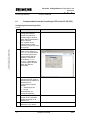
6.
The dialog which opens
allows setting further
parameters of the interface.
7.
Follow the other configuration
steps according to the INAT
manual and to the application
example and save your
configuration on the
"Echochange" gateway.
Configuring the S7-300 CPU
Table 6-3
No.
Instructions
Note
1.
Start the SIMATIC Manager
with the corresponding
configuration.
Create a new connection in
the network configuration
(NetPro).
2.
The connection is
"unspecified". As connection
type, select "ISO-on-TCP".
(In principle, you can also
select other alternatives.)
1.1
Ausgabe 23.02.2009
27/32
Structure, Configuration and Operation of the
Application
C fi
ti
Echochange-Gateway
Copyright © Siemens AG 2009 All rights reserved
23901499_Echochange-Gateway_DOKU_V10_e.doc
No.
Entry ID: 23901499
Instructions
Note
3.
Write down the "Block
Parameters". In step 5, the
values for "ID" and "LADDR"
have to be entered when
calling the "AG_RECV" block!
4.
The "Remote" IP address is
the address of the
"Echochange" gateway, not
that of the CLX CPU!
Please use the same
connection name ("TSAP",
"Transport Service Access
Point") as for the INAT
configuration.
5.
When configuring the CPU,
insert a network in which a
"AG_RECV" block is called.
The connection data which
you have created in the
network configuration have to
be transmitted to this block.
Moreover, a data area has to
be specified which can take
the data transmitted by the
ControlLogix CPU.
6.
To conclude, save and
transfer your project to the
SIMATIC CPU.
1.1
Ausgabe 23.02.2009
28/32
Structure, Configuration and Operation of the
Application
C fi
ti
Echochange-Gateway
6.2
Entry ID: 23901499
Communication from the S7-300 CPU to the ControlLogix CPU
Note
Please observe that for this functionality no connection has to be
configured in the Allen-Bradley ControlLogix controller. The
"Echochange" gateway can write onto the tags directly. Also see chapter
4.2.
Configuring the S7-300 CPU
Table 6-4
Copyright © Siemens AG 2009 All rights reserved
23901499_Echochange-Gateway_DOKU_V10_e.doc
No.
Instructions
Note
1.
Start the SIMATIC Manager
and define an Ethernet
connection following the
same steps as performed
under Table 6-3.
The parameterization must
correspond to the
configuration of the
"Echochange" gateway
(see Table 6-5).
2.
Insert a network into the
configuration of the SIMATIC
CPU which regularly calls the
"AG_SEND" block and thus
initiates the data
transmission.
The block has to be filled with
the data of the newly created
network configuration as well
as with the data area to be
transmitted.
3.
Save and transfer your
project to the SIMATIC CPU.
1.1
Ausgabe 23.02.2009
29/32
Structure, Configuration and Operation of the
Application
C fi
ti
Echochange-Gateway
Entry ID: 23901499
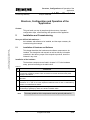
Configuring the "Echochange" gateway
Table 6-5
No.
Instructions
Note
In the INAT parameterizing
software, basically repeat the
configuration described under
Table 6-2.
Unlike the other
configuration, here the
interface communicating with
the ControlLogix CPU has to
be "active" and its IP address
has to be entered.
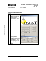
2.
Select in the protocol
definition a controller tag
"Tag Name" which has been
created in the ControlLogix
CPU. Without any further
configuration of the
ControlLogix CPU, the
transmitted data are written
into this variable.
Please make sure that the
tag ("ip_receive" in the
example on the right) is
configured in time and that
enough memory space is
reserved to take the
transmitted data.
Please observe that currently
only "INT" variables can be
transmitted.
3.
After having saved the
configuration, transfer it to the
"Echochange" gateway.
Copyright © Siemens AG 2009 All rights reserved
23901499_Echochange-Gateway_DOKU_V10_e.doc
1.
1.1
Ausgabe 23.02.2009
30/32
Appendix and Bibliography
Bibliography
Echochange-Gateway
Entry ID: 23901499
Appendix and Bibliography
7
Bibliography
7.1
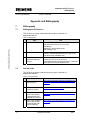
Bibliographic References
This list is by no means exhaustive and only gives a selection of
appropriate sources.
Table 7-1: Bibliography
Copyright © Siemens AG 2009 All rights reserved
23901499_Echochange-Gateway_DOKU_V10_e.doc
Topic
7.2
Title
/1/
STEP7
Automatisieren mit STEP7 in AWL und SCL
[Automation with STEP7 in STL and SCL]
Hans Berger
published by: Publicis MCD Verlag
ISBN 3-89578-113-4
/2/
"Echochange" basics
"Echochange" User Manual, manual version 0304-001
(German, "\download\handbuch\echan_d.pdf" on the
INAT Echochange installation CD)
/3/
"Echochange"
application example
S7-400
"TCP/IP Coupling between an Allen-Bradley
ControlLogix CPU and a S7-400 CPU"
("\download\infos\echochange\examples\clx_s7400.pdf"
on the INAT Echochange installation CD)
Internet Links
This list is by no means exhaustive and only gives a selection of
appropriate websites.
Table 7-2: Web addresses
Topic
1.1
Title
\1\
Reference to this
documentation
http://support.automation.siemens.com/WW/view/en
/23901499
\2\
Siemens A&D
Customer Support
http://www.ad.siemens.de/support
\3\
Entry in the automation
portal "Allen-Bradley
Communication with
PROFIBUS Scanners"
http://support.automation.siemens.com/WW/view/en
/23809864
\4\
Entry in the automation
portal "Allen-Bradley
Communication with
Anybus Gateway"
http://support.automation.siemens.com/WW/view/en
/23902276 (starting in fall 2006)
Ausgabe 23.02.2009
31/32
Appendix and Bibliography
Bibliography
Echochange-Gateway
Entry ID: 23901499
Topic
Title
Website of INAT GmbH
(manufacturer of the
"Echochange" gateway)
\6\
"Echochange" product
description
http://www.inat.de/index.php?255&backPID=255&tt
_products=268
\7\
"Allen-Bradley" website
http://www.ab.com
\8\
"Rockwell Automation"
website
http://www.rockwellautomation.com
Copyright © Siemens AG 2009 All rights reserved
23901499_Echochange-Gateway_DOKU_V10_e.doc
\5\
http://www.inat.de/
1.1
Ausgabe 23.02.2009
32/32