1
AIRDATA™ MULTIMETER
ADM-870C
ELECTRONIC MICROMANOMETER
WITH RS232 COMMUNICATIONS PORT
• AIR FLOW • VELOCITY • PRESSURE • TEMPERATURE •
OPERATING INSTRUCTIONS
CONTENTS
1.0 INTRODUCTION
1.1 KEY DIFFERENCES BETWEEN THE NEW ADM-870C AND THE ADM-870
1.2 GENERAL DISCUSSION
1
1
3
2.0 SPECIFICATIONS
4
3.0 EXTERNAL FEATURES
3.1 KEYPAD
3.2 FEATURES ON SIDES AND BACK OF METER
6
6
6
4.0 DISPLAY MESSAGES AND PROMPTS
4.1 READ PROMPTS
4.2 MEASUREMENT READOUTS
4.3 FUNCTION READOUTS
9
9
9
10
5.0 USING THE AIRDATA MULTIMETER
5.1 GENERAL USE
5.2 AUTOMATIC READINGS
5.3 TREND READINGS
5.4 MEMORY/AVERAGE/TOTAL FUNCTION
5.4.1 MEMORY OPERATION
5.4.2 RECALL
5.4.3 REPLACE READING IN MEMORY
5.4.4 ERASE READING IN MEMORY
5.4.5 CLEAR MEMORY
5.5 AUTOMATIC READING MEMORY
5.6 DATA DOWNLOAD TO A PRINTER
5.6.1 DOWNLOAD INDIVIDUAL READINGS TO A PRINTER
5.6.2 DOWNLOAD AUTOMATIC READINGS TO A PRINTER
5.6.3 DOWNLOAD READINGS IN MEMORY TO A PRINTER
5.7 DATA DOWNLOAD TO A COMPUTER
5.7.1 CONFIGURATION FILE SET-UP IN WINWEDGE
5.7.2 PORT AND DATA INPUT SETTINGS
5.7.3 FUNCTION KEY COMMANDS
5.7.4 SET-UP CONNECTIONS AND OPEN THE APPLICATIONS
5.7.5 INDIVIDUAL READINGS CONTROLLED FROM COMPUTER KEYBOARD
5.7.6 DOWNLOAD READINGS FROM MEMORY USING COMPUTER KEYBOARD
5.7.7 CONTROL BUTTONS, CURSOR CONTROL, AND FILE PATHS
5.7.8 AUTOMATIC REPEAT READINGS CONTROLLED BY WINWEDGE
5.7.9 MINIMIZING WINWEDGE
5.7.10 ALTERNATIVE DOWNLOAD METHOD
21
21
22
23
23
23
24
24
25
25
25
25
26
26
27
28
28
29
30
30
31
31
31
32
33
33
6.0 VELOCITY MEASUREMENT
6.1 VELOCITY CORRECTION FACTORS
6.2 PITOT TUBE VELOCITY MEASUREMENT
6.3 AIRFOIL PROBE VELOCITY MEASUREMENT
6.3.1 DUCT VELOCITY USING AIRFOIL PROBE
6.3.2 BIO-SAFETY CABINETS
6.3.3 EXHAUST HOODS - AIRFOIL PROBE
6.3.4 LAMINAR FLOW WORKSTATIONS - AIRFOIL PROBE
6.4 SINGLE POINT CENTERLINE AIR VELOCITY MEASUREMENTS
6.5 VELGRID AIR VELOCITY
6.5.1 CHEMICAL EXHAUST HOODS - VELGRID
6.5.2 LAMINAR FLOW WORKSTATION - VELGRID
34
34
36
37
38
38
39
40
40
40
41
41
i
ADM-870C 07/20/04
6.5.3 AIR FLOW CALCULATION FROM VELGRID VELOCITY
6.6 VELOCITY: LOCAL DENSITY VERSUS STANDARD DENSITY
41
41
7.0 PRESSURE MEASUREMENT
7.1 DIFFERENTIAL PRESSURE
7.1.1 STATIC PRESSURE PROBES
7.1.2 PITOT TUBE "VELOCITY PRESSURES"
7.1.3 PITOT TUBE "STATIC PRESSURES"
7.1.4 PITOT TUBE "TOTAL PRESSURES"
7.2 ABSOLUTE PRESSURE
44
44
44
45
45
45
45
8.0 TEMPERATURE MEASUREMENT
8.1 TEMPROBE
8.2 AIRDATA MULTITEMP
46
46
47
9.0 AIR FLOW MEASUREMENT
9.1 FLOWHOOD FUNCTION
9.2 BACKPRESSURE COMPENSATION
49
49
49
10.0 FLOWHOOD ASSEMBLY
10.1 UNPACKING
10.2 FRAME ASSEMBLIES
10.3 FABRIC TOPS
10.4 TOP SUPPORT ASSEMBLY
10.5 HANDLE
50
50
50
50
51
51
11.0 FLOWHOOD OPERATING PROCEDURE
11.1 AIR FLOW - NONBACKPRESSURE COMPENSATED READINGS
11.2 AIR FLOW - BACKPRESSURE COMPENSATED READINGS
11.2.1 MEMORY DISPLAY IN FLOWHOOD MODE
11.2.2 RATIO ERR DISPLAY
56
56
57
57
58
12.0 SPECIAL BALANCING PROCEDURES
12.1 PROPORTIONAL BALANCING
12.2 LARGE RETURN AIR GRILLES
12.3 KITCHEN EXHAUST HOODS
12.3.1 RANGE EXHAUST FILTERS AND GREASE EXTRACTORS
12.4 CONSTANT VOLUME CONTROLLERS
12.5 LINEAR SLOT DIFFUSERS
12.6 SIDEWALL REGISTERS
12.7 14"x14"x14" SHORT TOP SET
12.8 SYSTEM PROBLEMS
59
59
59
59
59
60
60
60
61
61
13.0 CORRECTION FACTORS
13.1 BAROMETRIC PRESSURE DENSITY CORRECTION
13.2 TEMPERATURE DENSITY CORRECTION
13.3 RELATIVE HUMIDITY CORRECTION
13.4 HOT WIRE ANEMOMETER VERSUS AIRDATA MULTIMETER
62
62
62
62
63
14.0 METER ACCURACY FIELD TESTING
14.1 METER ZERO FUNCTION
14.2 DIFFERENTIAL PRESSURE FUNCTION
14.3 ABSOLUTE PRESSURE FUNCTION
14.4 AIR FLOW ACCURACY
14.5 DUCT TRAVERSE COMPARISON, INCLINED MANOMETER, MICROMANOMETER
14.6 DUCT TRAVERSE USING THE AIRDATA MULTIMETER
64
64
64
64
64
65
65
ii
ADM-870C 07/20/04
14.7 BACKPRESSURE COMPENSATED COMPARISON READING
14.8 NONBACKPRESSURE COMPENSATED READING
66
66
15.0 METER MAINTENANCE
67
16.0 FLOWHOOD MAINTENANCE
68
17.0 RECALIBRATION AND REPAIR INFORMATION
69
AIR BALANCE MANUALS & TRAINING PROGRAMS
69
WARRANTY
70
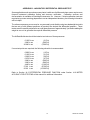
APPENDIX A - NIST VELOCITY TESTING
71
APPENDIX B - LABORATORY DIFFERENTIAL PRESSURE TEST
73
APPENDIX C - BATTERY TEST PROCEDURE
PROLONGING BATTERY LIFE
BATTERY RECYCLING
74
75
75
REPLACEMENT PARTS LIST
76
INDEX
78
Copyright © Shortridge Instruments, Inc., 2004. All rights reserved. This information
may not be reproduced or duplicated in any manner, or for any purpose, without
permission in writing from Shortridge Instruments, Inc.
U.S. PATENT NO. 4,481,829/4,754,651/4,911,021
iii
ADM-870C 07/20/04
ILLUSTRATIONS
3.1
6.1
6.2
6.3
7.1
8.1
8.2
10.1
10.2
10.3
10.4
10.5
10.6
10.7
10.8
ADM-870C METER FRONT AND BACK
PITOT TUBE
AIRFOIL PROBE
VELGRID ASSEMBLY
STATIC PRESSURE PROBE
ADT442 TEMPROBE
AIRDATA MULTITEMP
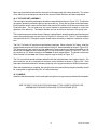
FRAME STORAGE
FLOWHOOD IN CASE
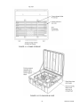
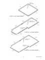
FLOWHOOD ASSEMBLY
2X2 FRAME ASSEMBLY
1X4 FRAME ASSEMBLY
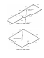
2X4 FRAME ASSEMBLY
1X5 FRAME ASSEMBLY
3X3 FRAME ASSEMBLY
8
36
38
42
44
46
47
52
52
53
54
54
54
55
55
iv
ADM-870C 07/20/04
1.0 INTRODUCTION
1.1 KEY DIFFERENCES BETWEEN THE NEW ADM-870C AND THE ADM-870
RS232 TO PORTABLE PRINTER
The new ADM-870C AirData Multimeter has an RS232 port that may be used with a portable printer.
The optional printer and cable can download each reading as it is taken, or the entire contents of the
memory can be downloaded and printed all at once.
RS232 TO COMPUTER USING WINWEDGE® OR HYPERTERMINAL
The RS232 link may be used in conjunction with either WinWedge® software and any 32 bit
Windows® (95, 98, ME, Windows NT® 2000 or XP) application or HyperTerminal® and Windows (95,
98, ME, 2000 or XP) to load readings directly from the meter into a spreadsheet format for display,
analysis, and manipulation. Data may also be downloaded from the meter into a word processing
format. The WinWedge software comes complete with an instruction manual, license, CD, and full
user support for WinWedge from the manufacturer, TAL Technologies, Inc. (www.taltech.com). The
software for HyperTerminal Private Edition for business use may be purchased online at
www.hilgraeve.com/htpe/order.html. HyperTerminal Private Edition comes with unlimited phone
support for 60 days from date of purchase and unlimited, free email and web support.
200 READING MEMORY
The ADM-870C has a 200 reading memory capacity with sequential storage and recall. The ADM860C and the prior version ADM-870 AirData Multimeter offer 100 reading memory storage.
MAXIMUM AND MINIMUM READING DISPLAY
The maximum and minimum readings in a stored sequence may now be displayed along with the
average and the sum of the readings.
READING SEQUENCE NUMBER
The reading sequence number is displayed during a sequence of stored readings.
STORED READING DELETION
Any reading in a stored sequence may be deleted or replaced. The new sum and average for the
revised sequence will be calculated and displayed. This replaces the prior method of using the RCL
keys to delete the last reading taken.
FLOWHOOD MODE SUMS AND AVERAGES
The averages and sums of stored FLOWHOOD mode readings are now displayed separately for the
backpressure compensated readings and nonbackpressure compensated readings. When the
STORE key is pressed repeatedly following a reading, the first display is the average of just the
backpressure compensated readings, followed by the display of the average of the nonbackpressure
compensated readings. Pressing the STORE key repeatedly again will display the sum of the
backpressure compensated readings, and finally the sum of the nonbackpressure compensated
readings.
READINGS STORED IN MEMORY WHILE METER IS TURNED OFF
Any readings stored in memory when the meter is turned off will be saved while the meter is shut
down. The next time the meter is turned on, it will default to the STORE mode which was selected
when the meter was last turned off using the meter keypad. The last reading stored in memory will
be displayed.
1
ADM-870C 07/20/04
DISPLAY
The ADM-870C has a new display that provides more information. It is also easier to read.
BACK-LIGHT
The new display has a back-light for use in low-light conditions. The back-light is turned on and off
by toggling the ON/OFF key. Note that use of the back-light significantly increases the load on the
batteries and reduces the operating time (measured by continuous reading operation) by about half.
It is difficult in normal light to tell if the back-light is on or off. The meter will display LIGHT ON when
the light is first turned on. The colon normally found in the third position from the left of the displayed
reading will be replaced by a schematic light symbol ('). The back-light may not be turned on if the
battery charge is too low. The display will read NO LIGHT/BATTERY/TOO LOW.
OFF KEY
The addition of the back-light feature required a change in the way the meter is turned off. The meter
is turned OFF by pressing SHIFT, then OFF.
SPEED-READ
The SPEED-READ feature has been replaced by the TREND mode. The TREND mode offers a
continuous series of readings at intervals of about once per second. The accuracy specifications do
not apply in TREND mode. A standard manual reading will be displayed after the TREND readings
have been halted by holding down the READ key.
METER AND BATTERY STATUS DISPLAY
All selected functions (measurement mode; units; local or standard density; TemProbe or standard
temperature being used for flow or velocity readings; manual readings, manual reading storage,
automatic readings or automatic reading storage) may always be read by pressing SHIFT/SHIFT.
The approximate level of charge remaining in the batteries will also be displayed. The display will
read BATT FULL if the batteries are highly charged. The display will read BATT 2/3, BATT 1/3, or
LOCHARGE as the level of charge decreases. No reading is taken, and no data is discarded.
POWER-ON DEFAULTS
The meter will initialize with the mode, units and memory storage status which were in effect when
it was last turned off by pressing SHIFT/OFF on the meter keypad, or was forced to shut down
automatically due to low voltage. This information will not be saved if the meter has been reset. If
the meter was in the STORE mode when it was turned off, the meter will display the mode, units and
the final reading of the last sequence in memory, when it is turned on again. Reading storage may
be resumed or the STORE mode may be exited by pressing SHIFT/CLEAR.
CALC DISPLAY ELIMINATED
The ADM-870C uses a much faster microcontroller than the ADM-870. Calculations occur almost
instantaneously. There is no need to display the CALC message.
BATTERY CHARGE INDICATOR LIGHT
A green LED on the front panel lights when the battery charger is properly connected.
LOCHARGE DISPLAY
When the battery charge is nearly depleted, the meter will display LOCHARGE. The colon normally
shown following the units for a displayed reading will be replaced by a symbol for an empty battery
cell. The meter will not display LOCHARGE again, but the symbol for the empty battery cell will
remain on the display.
2
ADM-870C 07/20/04
If the meter has been being used with the back-light turned off, the user will have approximately 20
minutes of runtime before the meter displays RECHARGE/SHUT DOWN and turns itself off. The
time period will vary considerably depending on prior use. The meter must be recharged prior to
further use.
If the meter has been being used with the back-light turned on, the user will have 5 to 20 minutes of
runtime before the meter displays RECHARGE/SHUT DOWN and turns itself off. The time period
will vary considerably depending on prior use. When this occurs, the meter may be turned back on
without the back-light and used until LOCHARGE is displayed again. The colon normally shown
following the units for a displayed reading will be replaced by a symbol for an empty battery cell. The
user will have 5 to 10 minutes of runtime before the meter displays RECHARGE/SHUT DOWN and
turns itself off. The meter must be recharged prior to further use.
1.2 GENERAL DISCUSSION
You will find these instructions much easier to follow if you have the meter in front of you as you read
through them. You can note the various connections and press the keys, observing the displayed
results as you read through the various procedures. The operation of the meter is quite simple and
straightforward, as will become apparent after a little practice.
The ADM-870C AirData Multimeter performs the following essential functions. This meter measures
air velocity when used with a pitot tube, AirFoil probe, or VelGrid and automatically corrects for
density variations due to local temperature and barometric pressure. Velocity ranges are 25-30,000
fpm using a pitot tube, 25-5,000 fpm using the AirFoil probe, and 25-2500 fpm using the VelGrid.
When used with the Series 8400 FlowHood System, this unit measures air flow and may compensate
for density and backpressure effects, allowing direct air flow readings from 25-2500 cfm. Accurate
differential pressure measurements can be obtained from 0.0001 in wc to 60.00 in wc. Absolute
pressure measurements range from 10-40 in Hg. Temperatures can be measured from -67/ F to
250/ F, either individually, or in conjunction with an air flow or velocity measurement.
The Model ADM-870C AirData Multimeter performs these additional functions which greatly simplify
the complex technical requirements of highly demanding test and balance projects. This model
features an automatic mode which registers repeated measurements for any capability, with
sequential storage and recall of up to 200 automatically or individually obtained measurements, with
sequence tags for each value. Recall of the sum, average, along with the minimum or maximum
readings in the stored sequence is available at any point, without terminating the process. Flow and
velocity measurements may be displayed in either local air density or the standard density (mass
flow) sea level equivalent.
The ADM-870C has an RS232 port that may be used with a portable printer. The optional printer and
cable can download each reading as it is taken, or the contents of the memory can be downloaded
and printed all at once. The RS232 link may also be used in conjunction with the optional WinWedge
software or HyperTerminal Private Edition and a computer to download readings directly into any 32
bit Windows® (95, 98, ME, NT 2000 or XP) application for display, analysis, and manipulation.
Internal calibration and zeroing of the AirData Multimeter are fully automatic. No external
adjustments are ever needed. This instrument is extremely tolerant of overpressure, and is
unaffected by position, motion, or ambient temperatures from 40/ F to 140/ F. It is recommended that
the AirData Multimeter kit be returned to the factory at least every two years for recalibration and
software update. This preventive maintenance program will assure that the original accuracy of the
meter is maintained throughout the life of the meter.
3
ADM-870C 07/20/04
2.0 SPECIFICATIONS
AIR VELOCITY: Measured in feet per minute (fpm), or meters per second (m/s), corrected for local
or standard air density. The measurement range is 25 to 30,000 fpm with a pitot tube, and 25
to 5,000 fpm with the Shortridge Instruments, Inc. AirFoil probe. The measurement range using
the VelGrid is 25 to 2500 fpm. Accuracy is ± 3% of reading ± 7 fpm from 50 to 8000 fpm. Pitot
tube velocity readings from 8,000 fpm to 30,000 fpm are based on compressible isentropic flow
theory and are not certified NIST traceable.
DIFFERENTIAL PRESSURE: Measured in inches of water column (in wc) or Pascals (Pa). The
measurement range is from 0.0001 to 60.00 in wc. Maximum safe pressures are 20 psid (900%
full scale) and 60 psia common mode. Accuracy is ± 2% of reading ± 0.001 in wc from 0.0500
to 50.00 in wc.
ABSOLUTE PRESSURE: Measured in inches of mercury (in Hg) or bars with reference to a
vacuum. The measurement range is 10-40 in Hg. Maximum safe pressure is 60 psia.
Accuracy is ± 2% of reading ± 0.1 in Hg from 14 to 40 in Hg.
TEMPERATURE: Measurement range is -67.0/ F to 250.0/ F. Accuracy is ± 0.5/ F from 32/ F to
158/ F with a resolution of 0.1/ F using the ADT442, ADT443, ADT444 or ADT445 TemProbes.
Safe exposure range for the TemProbes is -100/ F to 250/ F. Do not expose the plastic base
of the TemProbe or the extension wand to temperatures above 200/ F.
AIR FLOW: Measured in cubic feet per minute (cfm) or liters per second (L/s), corrected for air
density. This function requires the use of the Shortridge Instruments, Inc. Series 8400
Backpressure Compensating FlowHood System. The measurement range is 25 to 2500 cfm
supply and 25 to 1500 cfm exhaust. Accuracy is ± 3% of reading ± 7 cfm from 100 to 2000 cfm
(nonbackpressure compensated readings).
AIR DENSITY CORRECTION: The air density correction range is 14-40 in Hg and -67/ F to 250/ F
for correction of air flow and velocity measurements. The readings represent either local
density air flow or standard density sea level equivalent (mass flow) for air flow or velocity.
Readings are corrected for the density effects of temperature and absolute pressure.
MEMORY: 200 readings with sequential recall of each reading along with average, sum, minimum,
maximum.
RESPONSE TIME: Varies from one second at higher pressure inputs to seven seconds at less than
0.0003 in wc (70 fpm). Extremely low pressure/flow/velocity inputs require longer sample times
than higher pressure/flow/velocity inputs. TREND mode provides continuous readings in less
than two second intervals. (Accuracy specifications do not apply in TREND mode).
READOUT: Ten digit, 0.4 inch, liquid crystal display (LCD).
METER HOUSING: High impact, molded, "T" grade ABS.
METER WEIGHT: 36 ounces (1.02 kg), including batteries.
SIZE: 6.0" x 6.4" x 2.7" (15.2 x 16.3 x 6.9 cm).
4
ADM-870C 07/20/04
BATTERY LIFE: A ten-hour charge will normally allow two working days of heavy use, or up to 3000
readings per charge if the back-light is not being used. Increasing the charge time to 48 hours
(such as a weekend) will increase the working time by 25%. Continuous use of the back-light
may reduce the battery life by up to one half.
A set of rechargeable type AA NiCad batteries is supplied in each meter. Each battery has a
storage capacity of 1100 milliAmp hours. These batteries may be recharged up to 500 times
before replacement. If 1100 mAh batteries are not available in a field situation, 700 mAh
batteries (all 12 ) may be substituted. If 700 mAh batteries are mixed with 1100 mAh batteries,
the 700 mAh batteries may be damaged as the battery charge is depleted. If rechargeable
batteries are not available in a field situation, the batteries may be replaced with 12 nonrechargeable "AA" pen cell batteries.
WARNING: Do not plug the charger in if any non-rechargeable batteries are in the meter. The
meter will be seriously damaged along with the batteries and charger.
The approximate level of charge remaining in the batteries may be displayed by pressing
SHIFT/SHIFT. The display will read BATT FULL if the batteries are highly charged. The
display will read BATT 2/3, BATT 1/3, or LOCHARGE as the level of charge decreases.
NOTE: A battery charge level displayed when the meter is first turned on may not be
representative of the true level of battery charge. Wait five or ten minutes after turning the
meter on to view the charge status.
BATTERY CHARGERS: The battery charger (P/N PS8201) used in the U.S.A. and many other
countries requires 120 Volts AC, 60Hz, 8W. The battery charger (P/N PS8202) used in Europe
and certain other locations requires 220 Volts AC, 50Hz. Both chargers deliver 24 Volts AC to
the meter. Batteries may be left on charge for an unlimited time without harm. The
temperature of the instrument during charge should be kept between 40/ F and 113/ F (5/ C to
45/ C). The meter is fully operational during recharge.
OPERATIONAL TEMPERATURE LIMITS: The specified accuracy for measurements is maintained
over a meter exposure temperature range of 40/ F to 140/ F (5/ C to 60/ C).
STORAGE TEMPERATURE LIMITS: -4/ F to 140/ F (-20/ C to 60/ C).
AIR BLEED: Each pressure measurement requires a small volume of air to pass through the meter.
The pressure source must be capable of supplying this volume without significant depletion to
assure accurate measurements. Bleed through is typically 0.0004 cubic inch per in wc per
measurement. Quiescent bleed through (maximum) is 0.0005 cubic inch per in wc per minute.
TUBING: The maximum recommended length of pneumatic tubing for the measurement of air flow,
velocity, or differential pressure is 18 feet. Minimum tubing size is 3/16 inch, inside diameter.
The VelGrid is used with the two eight foot lengths of 3/16 inch ID tubing furnished with the kit.
5
ADM-870C 07/20/04
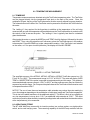
3.0 EXTERNAL FEATURES
3.1 KEYPAD
The meter keypad has eight keys, each of which may include multiple functions. Functions are
activated by pressing a function key once, twice or in sequence with other keys. This Instruction
Manual will often refer to a key by only one of the functions shown on the key.
A. Upper half of keys
Control name
B.
SILVER - active only after pressing "SHIFT" key.
Function
SHIFT
Shifts control from lower to upper half of keys.
DENS
Alternate action for local or standard density.
UNITS
Alternate action for English or metric units.
CLEAR
Clears memory, auto-read and average functions.
OFF
Turns the meter off after SHIFT key is pressed.
AUTO
Automatic repeat reading and TREND mode repeat.
Lower half of keys
Control Name
BLACK - always active except following SHIFT.
Function
MODE
Sequential action for all measurement modes (air flow, velocity, pressure and
temperature). Also used to erase, replace and print readings in STORE
mode.
ASSOC
Recalls associated temperature and pressure for flow and velocity
STORE
Activates memory mode, then alternate action for display of average, total,
minimum and maximum reading.
ON
Turns the meter on. Turns light on and off after meter has been turned on.
= RCL
Recalls stored readings in reverse order.
RCL <
Recalls stored readings in entry order.
READ
Initiate measurement or halt automatic readings.
3.2 FEATURES ON SIDES AND BACK OF METER
BATTERY CHARGER JACK
When viewed from the front, the battery charger jack is on the right side of the meter toward the
top. The battery charger plug is to be connected here.
6
ADM-870C 07/20/04
EXTERNAL READ JACK
When viewed from the front, the external read jack is on the left side of the meter toward the
top. The plug for the external thumbswitch is connected here. This feature allows the operator
to trigger measurements from the FlowHood or VelGrid handgrip while working overhead or in
awkward circumstances. The thumbswitch performs the same function as the READ key.
FLAPS JACK
The flaps jack is on the back of the meter, in the upper right hand corner. The flaps plug on the
FlowHood is inserted here.
TEMPERATURE INPUT JACK
The temperature input jack is centered on the back of the meter, slightly toward the top. The
flexible TemProbe sensor must be connected to this receptacle whenever temperature density
correction is desired for either flow or velocity measurements. A retractile cord connects the
TemProbe or the MultiTemp to the temperature input jack for remote temperature sensing.
RESET SWITCH
The reset pushbutton switch is on the back of the meter in a recess near the upper left corner.
This switch is used to reset the meter in the unlikely event that the microprocessor becomes
lost in its program. This may occur if the meter is dropped, and may cause the keypad to
become nonfunctional until the meter is reset. If the meter continues to fall into "lockout", it may
have been damaged, and should be returned for repair. Press the reset switch once to restart
the meter. Do not hold the switch down or press the switch twice in close sequence.
Information stored in memory will be saved in blocks of 50 readings if the meter must be reset
while readings are in memory. If the meter was turned off, then on again while readings were
in memory, but prior to resetting the meter, all readings saved prior to turning the meter off will
remain in memory after the meter is reset.
PNEUMATIC PRESSURE INLETS
Two pneumatic pressure inlets positive (+) and negative (-) are centered on the back of the
meter at the top edge and may be connected to various pressure sources for the measurement
of air velocity, flow, or pressure. Sources include the FlowHood, AirFoil probe, VelGrid, pitot
tubes, static pressure probes, or any other pressure source not exceeding the safe limits for
the meter. The negative (-) inlet senses the static pressure during flow or velocity
measurements, and also is used for direct absolute pressure measurements.
SERIAL PORT JACK
When viewed from the front, the serial port jack is centered on the right side of the meter just
below the battery charger jack. The circular plug of a custom RS232 serial cable is connected
here. The other end of the cable provides a standard DB9 connection for a printer or computer.
7
ADM-870C 07/20/04
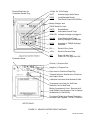
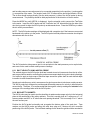
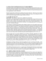
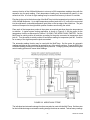
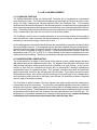
External Read Jack for
Pushbutton Handle Plug
10 Digit, 0.4" LCD Display
SHIFT
Activates Upper Half of Keys
DENS
MODE
Local/Standard Density
Flow/Press/Temp/VLG/AFP/Pitot
Battery Charger Jack
RS232 Serial Port Jack
UNITS
ASSOC
English/Metric
Associated Press & Temp
GRN LED Indicates if charger is plugged in
CLEAR
STORE
Clear Memory/Auto/Trend
Memory/Average/Total/Max/Min
AUTO
READ
Automatic or TREND Readings
Read/Halt
RCL <
Recall in Entry Order
= RCL
Recall in Reverse Order
OFF
ON
Power Off after Shift
Power On/ Turn Light On & Off
Pushbutton Reset
Positive (+) Pressure Port
Negative (-) Pressure Port
Flaps Jack for FlowHood Flaps Plug
Threaded Insert for Attachment to FlowHood
with Captive Screw
Calibration Label with Serial Number & Date
Temperature Input Jack for TemProbe,
Retractile Cord or MultiTemp
Battery Compartment Cover - Remove the 8
Small Phillips Head Screws to Test or Replace
the Batteries (12 AA NICAD)
Four Large Phillips Head Screws That Hold
the Meter Case Together - DO NOT REMOVE
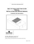
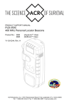
FIGURE 3.1 ADM-870C METER FRONT AND BACK
8
ADM-870C 07/20/04
4.0 DISPLAY MESSAGES AND PROMPTS
4.1 READ PROMPTS
The following ten prompts all include the term READ, which is a signal for the operator to press the
READ key to trigger the actual measurement.
English Units
CF: READ
This display indicates that the meter has been placed in the air flow function (cfm) and will
appear automatically upon power up if the flaps plug of the FlowHood is connected to the
meter.
/ F:
READ
This display indicates that the meter has been placed in the temperature function (/ F).
FP: READ
This display indicates that the meter has been placed in a velocity function (fpm).
Hg: READ
This display indicates that the meter has been placed in the absolute pressure function (in Hg)
with reference to a vacuum.
IN:
READ
This display indicates that the meter has been placed in the differential pressure function (in
wc).
Metric Units
Bar: READ
This display indicates that the absolute pressure readings will be displayed in bars (1 bar = 100
kPa) with reference to a vacuum.
/ C: READ
Display indicates that the temperature readings will be displayed in degrees Celsius (/ C).
LS: READ
This display indicates that the meter has been placed in the air flow function and will read in
liters per second (L/s).
MS: READ
This display indicates that the velocity readings will be displayed in meters per second (m/s).
Pa: READ
This display indicates that differential pressure readings will be displayed in Pascals (Pa).
4.2 MEASUREMENT READOUTS
In the following 12 examples, n indicates a number in the displayed result. If no sign is displayed,
the result is a positive number. A negative sign indicates a negative number. English and metric
units are shown for each example.
9
ADM-870C 07/20/04
English Units
CF:c ± nnnn
Indicates that the result represents an air flow measurement (cfm). "C" indicates that the result
has been compensated for backpressure effects.
CF:u ± nnnn
Indicates that the result represents an air flow measurement (cfm). "U" indicates that the result
has not been compensated for backpressure effects.
FP: ± nnnnnn
Indicates that the displayed result represents a velocity measurement (fpm).
/ F: ± nnn.n
Indicates that the displayed result represents a temperature measurement (/ F).
Hg: ± nn.n
Indicates that the result represents an absolute pressure measurement (in Hg).
IN: ± n.nnnn
Indicates that the result represents a differential pressure measurement (in wc).
Metric Units
Bar: n.nnn
Indicates that the result represents an absolute pressure measurement (bar). (One bar = 100
kPa).
/ C: ± nnn.n
Indicates that the displayed result represents a temperature measurement (/ C).
LS:c ± nnnn
Indicates that the result represents an air flow measurement (L/s). "C" indicates that the result
has been compensated for backpressure effects.
LS:u ± nnnn
Indicates that the result represents an air flow measurement (L/s). "U" indicates that the result
has not been compensated for backpressure effects.
Pa: ± nnn.nn
Indicates that the result represents a differential pressure measurement (Pa).
MS: ± nnn.nn
Indicates that the displayed result represents a velocity measurement (m/s).
4.3 FUNCTION READOUTS
The following prompts and messages are listed in alphabetical order.
$ $ $ $ $ $ $ $
Blocks of pixels will be displayed to test the operation of the display each time the meter is
turned on.
nnc nnnn
10
ADM-870C 07/20/04
Displays the number of backpressure compensated readings in memory and the average of just
the backpressure compensated readings taken during a FlowHood reading sequence. If there
are no backpressure compensated readings in memory, the display will read nnc NONE.
nnc NONE
Displayed if there are no backpressure compensated readings in memory during a FlowHood
reading sequence.
nnR n.nnnn
Displays the current reading and its place in the reading sequence during an automatic or
manual STORE sequence. Number of decimal places will vary.
nnR NP 0
Indicates that the current reading in an automatic or manual STORE sequence is a negative
pitot tube reading.
nnRc nnnn
This message indicates that backpressure compensated air flow readings are being stored.
The display shows the current reading and its order in the reading sequence during an
automatic or manual STORE process.
nnRu nnnn
This message indicates that nonbackpressure compensated air flow readings are being stored.
The display shows the current reading and its order in the reading sequence during an
automatic or manual STORE process.
nnS n.nnnn
Displays a reading in memory and its place in the stored reading sequence. Accessed using
forward or reverse RECALL keys. Number of decimal places will vary.
nnS ERASED
This message indicates that the current reading displayed in RECALL (nns) has been erased.
nns NP 0
This message is displayed when a stored negative pitot tube reading is accessed using a
RECALL key.
nnSc nnnn
This message indicates a backpressure compensated air flow reading is being viewed in
memory. The display shows the reading and its order in the reading sequence during an
automatic or manual STORE process. Accessed using the RECALL keys.
nnSu nnnn
This message indicates a nonbackpressure compensated air flow reading is being viewed in
memory. The display shows the reading and its place in the reading sequence during an
automatic or manual STORE process. Accessed using the RECALL keys.
11
ADM-870C 07/20/04
nnu nnnn
Displays the number of nonbackpressure compensated readings in memory and the average
of just the nonbackpressure compensated readings taken during a FlowHood reading
sequence.
nn
0 n.nnnn
Displays the number of readings in memory and the average of the readings. Displayed when
the STORE key is pressed after HALT during a STORE sequence. Number of decimal places
will vary.
3
n.nnnn
Displays the sum of the readings in memory. Displayed when the STORE key is pressed twice
after HALT during a STORE sequence. Number of decimal places will vary.
3c
nnnn
Displays the sum of the backpressure compensated readings in memory during a STORE
sequence. Displayed when the STORE key is pressed twice after HALT during a backpressure
compensated STORE sequence. Number of decimal places will vary. If there are no
backpressure compensated readings in memory, the display will read 3c NONE.
3c
NONE
This display indicates that there are no backpressure compensated readings in memory.
3u
nnnn
Displays the sum of the nonbackpressure compensated readings in memory during a STORE
sequence. Displayed when the STORE key is pressed twice after HALT during a
nonbackpressure compensated STORE sequence. Number of decimal places will vary.
xx' n.nnnn
This display indicates that the back-light is on and battery power draw has increased. xx
indicates the units for the reading.
xx
n.nnnn
This display indicates that the battery charge is nearly depleted. xx indicates the units for the
reading. The meter will also begin displaying LOCHARGE periodically.
xx › n.nnnn
This display indicates that the battery is highly charged. xx indicates the units for the reading.
The area of the battery symbol that is dark will decrease incrementally as the battery charge
declines.
xx6
n.nnnn
This display indicates that the meter is in TREND mode and that the readings are remaining
relatively constant. xx indicates the units for the reading.
xx_ n.nnnn
This display indicates that the meter is in TREND mode and that the readings are increasing
slowly. xx indicates the units for the reading.
12
ADM-870C 07/20/04
xx8 n.nnnn
This display indicates that the meter is in TREND mode and that the readings are increasing
rapidly. xx indicates the units for the reading.
xx` n.nnnn
This display indicates that the meter is in TREND mode and that the readings are decreasing
slowly. xx indicates the units for the reading.
xx9 n.nnnn
This display indicates that the meter is in TREND mode and that the readings are decreasing
rapidly. xx indicates the units for the reading.
¸
xx
n.nnnn
Displays the maximum (greatest value) reading stored in memory during a STORE sequence.
Displayed when the STORE key is pressed four times after HALT during the STORE sequence.
Number of decimal places will vary.
xx
n.nnnn
Displays the minimum (least value) reading stored in memory during a STORE sequence.
Displayed when the STORE key is pressed three times after HALT during the STORE
sequence. Number of decimal places will vary.
º
xx c nnnn
Displays the minimum reading of just the backpressure compensated readings stored in
memory during a STORE sequence. Displayed when the STORE key is pressed three times
after HALT during the STORE sequence. If there are no backpressure compensated readings
in memory, the display will read xx c NONE.
º
º
¸
xx c nnnn
Displays the maximum reading of just the backpressure compensated readings stored in
memory during a STORE sequence. Displayed when the STORE key is pressed three times
after HALT during the STORE sequence. If there are no backpressure compensated readings
in memory, the display will read xx c NONE.
¸
xx u nnnn
Displays the minimum reading of just the nonbackpressure compensated readings stored in
memory during a STORE sequence. Displayed when the STORE key is pressed three times
after HALT during the STORE sequence.
º
¸
xx u nnnn
Displays the maximum reading of just the nonbackpressure compensated readings stored in
memory during a STORE sequence. Displayed when the STORE key is pressed three times
after HALT during the STORE sequence.
ABS PRES
This signal will be flashed when the absolute pressure mode is selected, and also each time
the READ key is pressed when in the absolute pressure mode.
13
ADM-870C 07/20/04
ADM-870C
This message is flashed following $
$ $ $ $ $ $ $
when the meter is first turned on.
AIRFOIL
This signal will be flashed when the AirFoil probe mode is selected and also upon each
subsequent operation of the READ key.
AUTO
This message may be one of the parameters displayed following SHIFT/SHIFT and indicates
that the meter is being used in the automatic reading mode.
AUTO READY
This message indicates that the meter has been placed in the automatic reading function.
Press the READ key to start the actual measurement. Hold the READ key down until HALT is
displayed to halt the process.
AUTO STORE
This message indicates that the meter has been placed in the automatic memory mode, which
integrates the automatic reading function with the sequential storage function, and permits
recall of the readings, sum or average at any point. Press the READ key to initiate the actual
reading process. Press and hold the READ key until HALT is displayed in order to stop the
automatic reading sequence.
AUTO ZERO
When the meter is first turned ON, it will perform a self-calibration process that takes a few
seconds. The display will read AUTO ZERO during this period and the operating controls will
be inhibited. No READ operations or function changes may be made during the AUTO ZERO
period. The meter will also perform a brief self-calibration cycle periodically throughout normal
operation.
BATTERY
This message will appear as part of the NO LIGHT/BATTERY/TOO LOW sequence, when the
battery charge is too low to support use of the light.
BATT 1/3
This message indicates that about 1/3 of the useful battery charge remains. This message is
displayed every five minutes in manual mode and also following SHIFT/SHIFT.
BATT 2/3
This message indicates that about 2/3 of the useful battery charge remains. This message is
displayed every five minutes in manual mode and also following SHIFT/SHIFT.
BATT FULL
This message indicates that the batteries are fully (or close to fully) charged. This message
is displayed every five minutes in manual mode and also following SHIFT/SHIFT.
CF: CORR
This message indicates that the air flow measurement being performed is in cfm and will be
backpressure compensated.
14
ADM-870C 07/20/04
CF: UNCORR
This message indicates that the air flow measurement being performed is in cfm and will not
be backpressure compensated.
CHANGE
This message indicates that a connection to the meter, such as the TemProbe, has been
altered. CHANGE may be preceded by the display of the connection type.
CLEAR
This message is displayed when the operator has pressed SHIFT/CLEAR and no readings are
in memory.
CLEAR AUTO
This message is displayed when SHIFT/CLEAR is pressed while the meter is in the automatic
reading mode.
CLEAR MEM
This signal is flashed as the STORE, AUTO or TREND functions are cleared.
DIFF PRES
This signal will be flashed when the differential pressure mode is selected, and also upon each
subsequent operation of the READ key.
ENGLISH
This message indicates that the readings will be in English units. Pressing the SHIFT key and
then the UNITS key will switch the meter to metric units. The meter will save the units selection
(metric or English) and will automatically default to the selected units the next time it is turned
on.
ERASE n?
This message is displayed when the operator has pressed the MODE key twice while recalling
stored readings. The current reading displayed in RECALL (nns) will be erased when the
operator presses the READ key.
ERASING
This message is displayed when the current reading displayed using RECALL (nnS) is being
erased.
FLO-HOOD
This message will be flashed when the FlowHood mode is selected, or when the meter is first
turned on if the flaps plug is connected.
FLOW ONLY
FLOW ONLY will be displayed if the operator inserts the FlowHood flaps plug while the meter
is in a velocity or differential pressure mode and presses the READ key.
HALT
This message will be displayed when an automatic reading, automatic reading storage, or
TREND mode sequence has been halted manually by holding down the READ key. The
15
ADM-870C 07/20/04
individual readings, or the average, total, minimum and maximum of the readings, may now be
displayed if the auto-reading memory function is being used.
If the TREND mode is being used, the meter will switch back to manual reading mode and the
last reading displayed will be a standard manual reading.
LIGHT OFF
This message indicates that the display back-light has been turned off. Battery time is
extended when the back-light is turned off.
LIGHT ON
This message indicates that the display back-light has been turned on. Battery time is reduced
when the back-light is turned on.
LOCAL DENS
This message indicates that flow or velocity readings will be corrected for local air density. The
meter automatically starts up in the local density mode, unless the meter was last turned off
with readings stored in the standard density mode.
LOCHARGE
This message indicates that the battery cells are nearing the end of their useful charge. The
meter will continue to function normally for about twenty minutes, depending on light use,
before recharge is required. The third character of all displayed readings will become the
symbol for an empty battery cell. For example, FP: 983 will be displayed as FP 983, when
meter is registering LOCHARGE.
LS: CORR
This message indicates that the air flow measurement is in liters/sec and will be backpressure
compensated.
LS: UNCORR
This message indicates that the air flow measurement is in liters/sec and will not be
backpressure compensated.
MANUAL
This message may be one of the parameters displayed following SHIFT/SHIFT and indicates
that individual readings are being taken. The meter is not being used in either automatic
reading or memory mode.
MEM EMPTY
This message indicates that the meter is in STORE mode, but no readings have been saved.
METRIC
This message indicates that the readings will be in metric units. Pressing the SHIFT key and
then the UNITS key will switch the meter to English units. The meter will save the units
selection (metric or English) and will automatically default to the selected units the next time it
is turned on.
16
ADM-870C 07/20/04
NEG PITOT
This message indicates an invalid, negative, pitot tube velocity reading. This may result from
reversed tube connections to the meter, or from other conditions described in the section on
PITOT TUBE VELOCITY MEASUREMENT.
NO FLAPS
This message advises that the flaps plug on the FlowHood has not been connected to the
meter for air flow measurements. The meter senses the position of the flaps through the flaps
plug.
NO LIGHT
This message will appear as part of the NO LIGHT/BATTERY/TOO LOW sequence, when the
battery charge is too low to support use of the backlight.
NO LIGHT/BATTERY/TOO LOW
This sequence of messages indicates that the battery charge is low and the back-light may not
be used until the batteries are recharged.
NO PROBE
This message appears when the operator has neglected to install the TemProbe sensor prior
to initiating a temperature measurement. This term is also displayed if the TemProbe or
extension cord has been damaged so as to create an open circuit.
NOT ALLOWD
This message is displayed if the user tries to select STORE mode while in TREND mode.
NP
0
This message is displayed when a stored NEG PITOT reading is accessed using a RCL key.
OPEN FLAPS
This message advises that the operator has attempted to perform a nonbackpressure
compensated air flow measurement at greater than 500 cfm with the flaps closed. The flaps
must be opened to proceed.
OVER FLOW
This display advises the operator that the air flow measurement being attempted is beyond the
range of the meter.
OVER PRES
This display advises the operator that the pressure measurement being attempted is beyond
the range of the meter. OVER PRES may also be displayed if internal voltage settings or
linearity is out of proper range. (Contact factory if meter continues to read OVER PRES at
inappropriate times).
OVER TEMP
This display advises the operator that the temperature measurement being attempted exceeds
the upper range of the meter.
17
ADM-870C 07/20/04
OVER VEL
This display advises the operator that the velocity measurement being attempted is beyond the
range of the meter. OVER VEL may also be displayed if internal voltage settings are out of
proper range. (Contact factory if meter continues to read OVER VEL at inappropriate times).
PITOT TUBE
This signal will be flashed when the pitot tube mode is selected, and also upon each
subsequent operation of the READ key.
PRINT MEM?
This message is displayed when the operator has selected the print mode by pressing the
STORE key, followed by the MODE key. If an appropriate printer is connected to the RS232
jack and the READ key is pressed, the entire contents of the memory will be downloaded to the
printer. This message is also displayed whiled readings are being downloaded to a computer
using HyperTerminal.
PRINTING
This message is displayed when the operator is printing readings from memory by selecting
PRINT MEM? and then pressing the READ key.
PROBE
This message is displayed following SHIFT/SHIFT if the TemProbe is connected.
RATIO ERR
This message advises the operator that the backpressure compensated air flow measurement,
which is in process, is invalid because the numerical ratio of the two parts of the measurement
sequence exceeds the predetermined limits. Normally, this means that the operator has made
a procedural error, or that a dynamic change (such as a changed damper setting) has occurred
between the two parts of the backpressure compensated air flow measurement process.
READING
This message is displayed during differential pressure measurements, and also during the first
reading period of some automatic reading sequences. It is also displayed during the manual
reading which is taken when a sequence of TREND readings is halted.
RECHARGE
This message signals that the batteries have reached the end of their useful charge, and must
be recharged. The meter will turn off following the display of RECHARGE.
REPL nn?
This message is displayed when the operator has pressed the MODE key once while recalling
stored readings. This message indicates the current reading displayed using RECALL (nnS) will
be replaced with a new reading when the operator presses the READ key.
REPLACING
This message is displayed when the current reading displayed using RECALL (nnS) is being
replaced with a new reading.
18
ADM-870C 07/20/04
SHIFT
This message is displayed when the upper half of the keys are activated by pressing the SHIFT
key.
SHUT DOWN
The meter will display SHUT DOWN and turn itself off if the battery charge becomes too low
or if the meter is exposed to temperatures beyond the specified limits.
STD 70/ F or STD 21.1/ C
This message will be flashed during air flow or velocity measurements performed without the
TemProbe. The resulting flow or velocity value will be calculated using the standard
temperature, 70/ F or 21.1/ C. The correction for the ambient barometric pressure will still
occur.
STORE
This message may be one of the parameters displayed following SHIFT/SHIFT and indicates
that the meter is being used in the STORE mode.
STORE FULL
This message indicates that the number of readings in memory has reached the maximum
storage capacity of 200 readings.
STORE MODE
This message is displayed when a key other than READ, STORE or RCL is pressed when
readings are in memory and HALT has been selected. This message may be displayed when
the SHIFT key is pressed to indicate that the meter is in the STORE mode. The mode may not
be changed until the readings in memory are cleared by pressing SHIFT/CLEAR.
STORE RDY
This message indicates that the meter has been placed in the memory mode, and that readings
will be sequentially stored in memory when the READ key is pressed.
STD DENS
This message indicates that readings will be calculated to display standard density sea level
equivalent (mass flow). It will also be displayed during the actual measurement interval.
TEMP
This signal will be flashed when the Temperature mode is selected, and also upon each
subsequent operation of the READ key.
TEMPROBE
This message is displayed to indicate a change in the TemProbe connection status during a
STORE sequence.
TOO HOT or TOO COLD
If the internal temperature of the meter exceeds its operational limits, it will display TOO HOT
or TOO COLD and shut down. However, if there are readings in memory, the meter will
continue to display TOO HOT or TOO COLD, and will retain the readings in memory. The
meter must be cooled down or warmed up, as the case may be, before normal operation can
be resumed. If the meter has displayed OVER RANGE after displaying either TOO HOT or
19
ADM-870C 07/20/04
TOO COLD, but has not shut down, this message indicates that the TemProbe sensor was
being exposed to temperature levels beyond the proper operating range. If TOO HOT/OVER
RANGE has been displayed, but the meter has not shut down, the TemProbe sensor may be
short circuited.
TOO LOW
This message will appear as part of the NO LIGHT/BATTERY/TOO LOW sequence, when the
battery charge is too low to support use of the light.
TREND RDY
This message is displayed when the meter has been placed in the TREND mode. TREND
readings are not certified for accuracy.
UNDER TEMP
This display advises the operator that the temperature measurement being attempted exceeds
the lower range of the meter
UNITS - XX
This message will be displayed to indicate the units in which readings are being stored. It is
also one of the parameters displayed after SHIFT/SHIFT is pressed.
VELGRID
This signal will be flashed when the VelGrid mode is selected, and also upon each subsequent
operation of the READ key.
20
ADM-870C 07/20/04
5.0 USING THE AIRDATA MULTIMETER
5.1 GENERAL USE
The ADM-870C keypad has eight keys, five of which are dual-purpose keys. The dual-purpose keys
are OFF/ON, AUTO/READ, CLEAR/STORE, UNITS/ASSOC, and DENS/MODE. The functions
shown in the lower, dark colored section of each key may be activated by pressing the desired key.
The functions in the upper, silver colored sections of the keys are accessed by first pressing the
SHIFT key, then the key of the desired function.
Press the ON key to turn the meter on. The meter will display a row of pixel blocks to test the display,
and will then display AUTO ZERO while performing a brief internal calibration test.
The MODE key may be pressed repeatedly to select one of the following measurement modes:
temperature, VelGrid velocity, AirFoil probe velocity, pitot tube velocity, differential pressure, absolute
pressure. Selecting the FlowHood air flow mode is discussed in the next paragraph. When a mode
is selected, the meter will briefly display the mode, followed by a two-letter symbol for the units to be
used, and then display READ. For example, if the mode selected is pitot tube, the message would
read PITOTUBE briefly, followed by FP: READ.
If the FlowHood flaps plug has been plugged into the meter, the meter will initialize in the FlowHood
measurement mode, and will display FLO-HOOD briefly, followed by CF: READ. Press the Mode
key repeatedly while the flaps plug is connected to cycle the meter through the only measurement
modes which are appropriate when the meter is used on the FlowHood assembly. These modes are
temperature, absolute pressure and air flow.
Press the READ key to take a reading in the selected mode. The meter will briefly display the
selected function again, followed by the measurement result. Pressing the READ key again will
trigger another measurement, which will clear all previous data from the display and display the new
result.
The display has a back-light for use in low-light conditions. The back-light may be turned on or off
by pressing the ON/OFF key while the meter is turned on. The display will read LIGHT ON or LIGHT
OFF as appropriate. The third character (colon) in each READ display is replaced by a schematic
light symbol (') when the light is on.
Note that using the back-light significantly increases the drain on the batteries and reduces operating
time (continuous reading operation) by about 50 percent. The back-light may not be turned on when
the battery charge is very low. The display will read NO LIGHT/BATTERY/TOO LOW.
The back-light will turn off automatically if the meter has not been used for several minutes. Press
any key to turn the light back on.
The meter is turned off manually by pressing the SHIFT key, and then pressing the OFF key. The
meter will turn itself OFF automatically to save battery power if the meter has not been used for
several minutes, unless there are stored readings in memory or the meter has been placed in TREND
mode.
The meter saves any readings stored in memory, the measurement mode (pitot tube or differential
pressure, for example) and the type of units (English or metric) during a normal shut-down, and will
21
ADM-870C 07/20/04
default to the stored settings when turned on again. The last reading stored in memory will be
displayed.
Information stored in memory will be saved in blocks of 50 readings if the meter must be reset while
readings are in memory. If the meter was turned off, then on again, while readings were in memory,
but prior to resetting the meter, all readings saved prior to turning the meter off will remain in memory
after the meter is reset.
The AA NICAD batteries supplied with the meter are capable of supplying power for more than 3000
readings after one 10-hour charge. When the batteries are nearing the end of their useful charge,
the meter will begin displaying LOCHARGE and the symbol of a discharged battery cell will appear
in the third block of the displayed reading. The operator should act to complete the reading session
when LOCHARGE is displayed and record any readings in memory that might be lost if the meter
were to run out of power and shut down automatically due to extremely low charge.
If the meter is being used with the back-light turned off, the user will have approximately 20 minutes
of runtime before the meter displays RECHARGE/SHUT DOWN and turns itself off. The time period
will vary depending on prior use. The batteries must be recharged prior to further use.
If the meter is being used with the back-light turned on, the user will have approximately 5 to 20
minutes of runtime before the meter displays RECHARGE/SHUT DOWN and turns itself off. The
time period will vary depending on prior use. The meter may be turned back on without the backlight and used until LOCHARGE is displayed. The colon normally shown following the units for a
displayed reading will be replaced by a symbol for an empty battery cell. The user will have 5 to 10
minutes of runtime before the meter displays RECHARGE/SHUT DOWN and turns itself off. The
batteries must be recharged prior to further use. See Section 2.0 SPECIFICATIONS and APPENDIX
C for more information about the batteries and the battery charger.
The battery status and reading selections in effect can always be viewed by pressing SHIFT/SHIFT.
The first display represents the approximate level of charge remaining in the batteries. The display
will read BATT FULL if the batteries are highly charged. The display will read BATT 2/3, BATT 1/3,
or LOCHARGE as the level of charge decreases. The meter will then display the measurement mode
(for instance, VelGrid) and the units selected (English or metric). If the temperature probe is not
being used during flow or velocity readings, the standard temperature (STD 70/ F or STD 21.1/ C)
will be displayed. NOTE: A battery charge level displayed when the meter is first turned on may not
be representative of the true level of battery charge. Wait five or ten minutes after turning the meter
on to view the charge status.
The associated function (ASSOC key) allows the user to view the differential pressure, absolute
pressure and temperature associated with a pitot tube velocity reading. The absolute pressure and
temperature associated with an AirFoil probe, VelGrid or air flow reading may also be viewed. While
the reading is being displayed, press ASSOC repeatedly. The meter will display, in sequence, the
temperature used for air density adjustment (if NO PROBE, the standard temperature will be used),
the barometric pressure for air density adjustment, and, for pitot tube mode only, the differential
pressure measured across the input ports.
5.2 AUTOMATIC READINGS
Automatic sequential readings are initiated by first selecting the function and units keys required, then
pressing the SHIFT key and the AUTO key. The meter will display AUTO READY. Pressing the
READ key starts the actual measurement process. The automatic reading sequence may be
22
ADM-870C 07/20/04
interrupted by holding the READ key down. Release the READ key when HALT is displayed. The
automatic reading sequence will be resumed if the READ key is pressed again. The automatic
reading function may be exited while in HALT by pressing the SHIFT key, followed by the CLEAR
key.
5.3 TREND READINGS
TREND mode displays a continuous series of readings about once per second. TREND mode is
ideal for closely tracking a changing environment, such as when damper settings are being changed.
TREND displays a continuous series of readings as the air velocity or flow being adjusted
approaches the set point.
TREND mode sequential readings are optimized for speed, not accuracy. When the air has
stabilized near the required setting, the meter can be switched to the MANUAL reading mode for
more accurate readings.
TREND mode is selected by pressing SHIFT/AUTO and then SHIFT/AUTO again. Press and hold
down READ until the meter displays HALT to halt the TREND reading mode. The meter will switch
back to manual reading mode and the last reading displayed will be a standard manual reading.
5.4 MEMORY/AVERAGE/TOTAL FUNCTION
The memory/average/total function may be used with any of the measurement modes and allows the
storage of up to 200 individual readings for later recall of each reading, the average and sum of the
readings, and the minimum and maximum readings. This capacity may be used to facilitate such
tasks as pitot tube duct traverses, VelGrid face velocity measurements, and the recording of outlet
readings. These functions also assist in the averaging of coil face velocities and temperatures, static
pressures, and pressure drop readings.
The STORE key is used only with the memory related functions and serves several purposes.
Pressing the STORE key places the meter in the memory function. Press the STORE key after
readings have been entered into memory to alternately display the average, the sum, the minimum
and the maximum reading. The memory is cleared by pressing the SHIFT key and then the CLEAR
key.
The meter stores individual readings with greater resolution than the rounded figures that are
displayed. These numbers are used to calculate the sum and average. Therefore, there may be a
very small difference between the sum and average calculated by the meter and a sum and average
calculated by the user from the individual readings.
5.4.1 MEMORY OPERATION
Press the MODE key. The meter will flash the selected function followed by a READ prompt. Press
the STORE key. The meter will display STORE RDY and is now ready to store a sequence of
readings. Press the READ key to take a reading. The meter will display the mode, and then the units,
prior to displaying the first reading. If readings are being taken in flow or velocity, either LOCAL
DENS or STD DENS will also be displayed. If the TemProbe is not in place during flow or velocity
measurements, the meter will display STD 70/ F or STD 21.1/ C prior to the display of the first
reading. Readings will be displayed as nnR nn, where nnR is the sequence number of the reading
and nn is the actual reading. Subsequent readings will be displayed in succession.
The reading and memory entry process will continue as long as the READ key is pressed (up to a
maximum of 200 readings). Press the STORE key at any point to view the sum and the average.
23
ADM-870C 07/20/04
The number of readings that have been taken, along with the average of the readings will be
displayed, such as 07 395. The first two or three digits are the number of readings taken. Press
the STORE key again to display the sum of the readings. The number of readings in memory will not
be displayed with the sum.
0
Press the STORE key again to display the minimum reading. The sequence number of the reading
will be displayed along with the minimum reading, such as xx n.nnnn. Press the STORE key again
to display the maximum reading. The sequence number of the reading will be displayed along with
the maximum reading, such as xx
n.nnnn. The measurement sequence may be resumed by
pressing the READ key, and may be interrupted at any point by pressing the STORE key again.
º
¸
The measurement mode or other conditions may not be changed while the meter is in the memory
function.
Air flow readings may be saved as either a sequence of nonbackpressure compensated readings,
or as a sequence of alternating nonbackpressure compensated and backpressure compensated
readings, with display of the sum, average, minimum and maximum reading available for each type
of reading. See Section 11.1 AIR FLOW - NONBACKPRESSURE COMPENSATED READINGS
and Section 11.2 AIR FLOW - BACKPRESSURE COMPENSATED READINGS for more information.
The TemProbe must not be connected or disconnected during a STORE sequence. If this occurs,
TEMPROBE will be displayed followed by CHANGE. The TemProbe must be reconnected or
disconnected before further readings can be taken. The STORE mode may be exited by pressing
SHIFT/CLEAR if no further readings are needed.
If the meter's full capacity of 200 readings has been reached, STORE FULL will be displayed. Press
the STORE key to alternately display the average and sum, or one of the RCL keys for recall of the
individual readings. The memory must be cleared before a new reading sequence may be begun.
5.4.2 RECALL
The RCL keys are used while a reading sequence is halted to sequentially recall all readings that are
in memory. = RCL displays the last reading stored, and then displays readings in reverse order. RCL
< displays the first reading stored, and then displays readings in the order entered. These keys may
be used either before or after the STORE key has been pressed. The sequence of the reading will
be displayed along with the reading, such as 07s 395. A brief press of a RCL key will advance the
display one number at a time. Holding a recall key down will fast forward or fast reverse the display
through all the numbers that are in memory.
5.4.3 REPLACE READING IN MEMORY
A reading in memory may appear to be abnormal, or may have been taken at the wrong time, or with
an improperly positioned sensor. Readings stored in memory may be replaced with a new
measurement. Press one of the RCL keys to toggle through the individual readings in the stored
sequence. Select a specific reading such as: 07s 395. This reading may be replaced while it is on
display by pressing the MODE key. REPL n? will be displayed where n is the sequence number for
that reading. Press the READ key. The meter will initiate a new reading and the result will replace
the value previously stored for that position in the sequence. REPLACING will be displayed while
the meter takes the new reading and stores it to memory. The new sum and average will be
calculated using the new measurement and may be displayed by pressing the STORE key.
5.4.4 ERASE READING IN MEMORY
24
ADM-870C 07/20/04
Readings stored in memory may be erased without replacement. Press one of the RCL keys to
toggle through the individual readings in the stored sequence. Select a specific reading such as: 07s
395. This reading may be erased while it is on display by pressing the MODE key twice. ERASE n?
will be displayed where n is the sequence number for that reading. Press the READ key. ERASING
will be displayed. The erased reading will now be displayed as nnS ERASED. There will be no
value associated with that place in the sequence and the reading may be left blank or may be
replaced with a new reading. The sum function will disregard the erased reading unless it is
replaced. The average function will display the revised number of readings included in the average
and the average of the revised sequence.
5.4.5 CLEAR MEMORY
The memory is cleared and the STORE mode is exited by pressing the SHIFT key followed by the
CLEAR key. This sequence removes all readings from memory. Press the STORE key a second
time and a new averaging sequence will be initiated. NOTE: Readings are still in memory after the
SHIFT key has been pressed. Pressing the SHIFT key a second time will return the meter to the
previous mode, display all existing parameters and the existing readings will remain in memory.
5.5 AUTOMATIC READING MEMORY
The automatic reading function and the memory function may be combined to gain the increased
resolution afforded by the increased time base of the measurement interval. This function permits
the operator to store up to 200 fully automatic, repeated readings for the same function. This
measurement and storage process will continue until interrupted by the operator, or until the meter
registers STORE FULL at 200 readings.
The auto-reading memory sequence is initiated by first pressing the function and units keys required.
Then press the SHIFT key, followed by the AUTO key, then press the STORE key. The meter will
display AUTO STORE, at which point the actual measurements are initiated by pressing the READ
key.
The auto-reading memory sequence may be interrupted by holding the READ key down until HALT
is displayed. The auto-reading memory sequence will be resumed if the READ key is pressed again.
This function may be exited by holding the READ key down until the display reads HALT, then
pressing the SHIFT key followed by the CLEAR key. When the auto-reading memory sequence has
been completed or interrupted, press the STORE key. The number of readings and the average will
be displayed. Press the STORE key again to display the sum of the readings. Pressing the STORE
key in sequence will display the minimum, and then the maximum reading. Press one of the RCL
keys to recall individual readings.
5.6 DATA DOWNLOAD TO A PRINTER
Readings may be downloaded directly from the meter to a printer, either as individual readings or
multiple readings from memory. Shortridge Instruments, Inc. supplies the Seiko™ model DPU-H245,
a palm-sized, portable printer which uses rechargeable batteries. Other compatible printers may also
be used.
The Seiko model DPU-H245 printer is shipped complete with an RS232 printer (serial) cable, null
modem adapter, battery and power cable.
Connect the barrel connector on the serial cable to the RS232 jack on the right side of the meter.
The red dot on the connector aligns with the red rectangle on the lower part of the jack. Connect the
null modem adapter to the DB9 connector on the serial cable and then plug the null modem adapter
25
ADM-870C 07/20/04
into the serial port on the printer.
Refer to the instructions supplied by the printer manufacturer for any further setup requirements. The
RS232 port on the meter is set for 9600 BAUD, 8 data bits, no parity, and one stop bit. There is no
flow control.
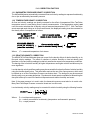
5.6.1 DOWNLOAD INDIVIDUAL READINGS TO A PRINTER
Turn the meter and the printer on. The default mode and units will be printed if the printer is turned
on before the meter. Select the desired mode and units and press the READ key. The printer will
print the information displayed throughout the reading sequence, including the mode, density
selections, and readings. Press the READ key to print another reading. Example printouts are shown
below.
If DIFF PRES and ENGLISH are selected and the READ key is pressed, the following will be printed:
DIFF PRES
In: 0.0468
If a velocity or flow mode is selected and the TemProbe is being used, when the READ key is
pressed, the printout will be formatted like the following:
VELGRID
LOCAL DENS
FP: 1576
If a velocity or flow mode is selected and the TemProbe is not being used, when the READ key is
pressed, the printout will be formatted like the following:
VELGRID
LOCAL DENS
STD 70/ F
FP: 1576
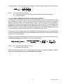
5.6.2 DOWNLOAD AUTOMATIC READINGS TO A PRINTER
Turn the printer on and then turn the meter on. The mode and units saved by the meter during the
most recent use will be printed. Select the desired mode and units and then press SHIFT/AUTO to
place the meter in the automatic reading mode. Press the READ key. The printer will print the mode
and density selections, followed by each of the readings in direct sequence. Hold the READ key
down at any time to halt the reading sequence and stop the printing process. Pressing the READ key
again will start the automatic reading and printing process again. An example of readings printed
from the automatic reading mode is shown below.
VELGRID
LOCAL DENS
FP: 1576
FP: 1589
HALT
VELGRID
FP: 1561
HALT
26
ADM-870C 07/20/04
FP: 1590
FP: 1561
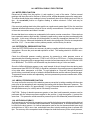
5.6.3 DOWNLOAD READINGS IN MEMORY TO A PRINTER
Readings stored in memory may be downloaded from the meter to a printer after the sequence of
readings has been completed. Connect the printer to the meter using the RS232 cable as described
in Section 5.6 DATA DOWNLOAD TO A PRINTER. Turn the printer and meter on.
Press the STORE key, then the MODE key. PRINT MEM? will be displayed. Press the READ key
to download all readings stored in memory to the printer. PRINTING will be displayed while the
readings are being printed. The readings will remain stored in the meter memory until the memory
is cleared by pressing the SHIFT key, followed by the CLEAR key. An example of readings printed
from memory in the VelGrid mode is shown below:
VELGRID
LOCAL DENS
STD 70/ F
01
1576 FP
02
1581 FP
03
1578 FP
04
1577 FP
Sum
6312 Fp
004 Avg 1578 F
001 Min 1576
002 Max 1581
Std Dev 2.2
An example of readings printed from memory in the FlowHood mode is shown below:
FLO-HOOD
LOCAL DENS
01
1474 CFu
02
1524 CFc
03
1482 CFu
04
1531 CFc
002 Avg c
1527
002 Avg u
1478
Sum c
3055
Sum u
2956
002 Min c
1524
001 Min u
1474
004 Max c
1531
003 Max u 1482
Std Dev c
4.9
Std Dev u
5.7
5.7 DATA DOWNLOAD TO A COMPUTER
Readings from the ADM-870C AirData Multimeter may be automatically transmitted to specific cells
of a computer spreadsheet such as Microsoft Excel™ for display, analysis and manipulation. This
functionality requires either HyperTerminal Private Edition or WinWedge software from TAL
27
ADM-870C 07/20/04
Technologies, Inc. as well as an RS232 serial cable. The procedure using HyperTerminal is supplied
in a separate document supplied with the ADM-870C AirData Multimeter.
WinWedge collects data from scales and balances, gauges, laboratory instruments, meters, sensors
or any other RS232 instrument or serial device and inputs the data directly into Microsoft Excel or any
other Microsoft Windows application program.
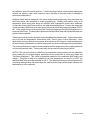
Configuration files must be set up to specify how WinWedge will interact with the AirData Multimeter
(or with any other device). A series of fully functional, example Configuration Files is provided along
with the WinWedge software to help the user become familiar with the program. These Configuration
Files are extremely easy to use and are provided so the most basic set-up will occur automatically
and provide the user with an introduction to the available features. The Configuration Files may be
copied repeatedly and each copy may be modified as required to suit the needs of the user.
An easy step-by-step set of instructions, titled GET A QUICK START USING THE WINWEDGE
CONFIGURATION FILES, is also provided along with the sample Configuration Files.
All of the port settings, data input settings, output settings, function keys, mouse buttons and other
information required to use WinWedge with the AirData Multimeter have already been set up in each
of the example Configuration Files. These files are ready to be used as soon as they are loaded onto
a computer along with WinWedge. These files may also be copied repeatedly and each copy
modified as required to suit the needs of the user.
It is recommended that the user begin by reading the relevant sections of the WinWedge software
User’s Manual to become familiar with issues of configuration, settings, output formats and any other
areas of interest. The following information is only a preliminary exposure to the WinWedge
capabilities.
Register the serial number of your WinWedge software to become eligible for free technical support
from the software manufacturer. More information is also available in the WinWedge User’s Manual.
The contact information for registration and technical support is:
TAL Technologies, Inc.
www.taltech.com
5.7.1 CONFIGURATION FILE SET-UP IN WINWEDGE
Configuration files must be defined and saved prior to using WinWedge. The WinWedge Set-up main
menu has three pull-down menu selections for access to the most important set-up windows required
for use with the AirData Multimeter. These windows are used to determine the basic structure of
configuration files used by WinWedge for receiving a data stream, processing the data received, and
transmitting it to specific cells of a spreadsheet.
Mode > Send Keystrokes To
Port > Settings
Define > Input Data Record Structure
> Pre-Input Character Translations
> Pre-Transfer Character Translations
> Serial Output Strings
> Hot Keys and Hot Key Actions
28
ADM-870C 07/20/04
The Mode > Send Keystrokes To selection defines the destination of the information downloaded
from the meter. A spreadsheet must be open and active before using this option. If no destination
has been specified, WinWedge will transmit the first field of the data stream to the location of the
cursor on the spreadsheet that is open and active.
Port > Settings is discussed in Section 5.7.2 PORT AND DATA INPUT SETTINGS.
The Define > Input Data Record Structure must be defined for WinWedge to decipher the incoming
stream of data and deliver the required data to the appropriate spreadsheet cell. The AirData
Multimeter downloads data in a set of comma-delimited fields in ASCII format. This incoming data
will be analyzed by the Port > Analyze function in WinWedge. The required data conversion is
entered using Define > Input Data Record Structure, Define > Pre-Input Character Translations, and
Define > Pre-Transfer Character Translations.
The number and type of fields which are downloaded from the meter into WinWedge, and therefore
to the spreadsheet, depends on the type of measurement being taken. Possible fields include the
measurement command type, measurement mode, density selection, standard temperature
assumption, value of reading, and units. The user may require a download format that includes only
certain fields. This requires setting the WinWedge Define > Input Data Record Structure to ignore
all other data fields and transfer only the relevant data field for each reading.
Define > Serial Output Strings is discussed in Section 5.7.8 AUTOMATIC REPEAT READINGS
CONTROLLED BY WINWEDGE. Define > Hot Keys and Hot Key Actions is discussed in Section
5.7.3 FUNCTION KEY COMMANDS.
The user’s completed set-up selections should be saved in a configuration file before being used
unless the user is in Test Mode. Configuration files will be automatically saved in the same folder
with WinWedge. Each configuration file will remain available for repeated use and modification.
All of the information in this section is discussed in much greater detail in the WinWedge User’s
Manual.
5.7.2 PORT AND DATA INPUT SETTINGS
The following port and data input settings are required for use with the ADM-870C AirData
Multimeter:
Port: COM1 (an alternative serial port may be selected in Port > Settings)
Baud: 9600
Parity: None
Data Bits: 8
Stop Bits: 1
Flow Control: None
Input Buffer Size: 8192 The input buffer size needs to be large enough to store the 200 reading
memory.
Output Buffer Size: 512 The output buffer size only needs to be large enough for the ASCII
command strings. The default of 512 is more than adequate.
5.7.3 FUNCTION KEY COMMANDS
29
ADM-870C 07/20/04
The meter may be controlled from a computer keyboard by the use of function keys. Pressing a
function key sends a command or a series of commands to the meter. The meter recognizes the
command and responds by changing modes, taking a reading, or downloading stored readings from
memory. The function keys are set up in the WinWedge Setup window under the menu option Define
> Hotkeys and Hotkeys Action.
The list of commands used by the meter and the resulting action are specified in the list of
recommended function keys shown below. For example, D<CR> (<CR> represents a hard return)
changes the meter mode to Differential Pressure. WinWedge uses the musical note symbol that is
#13 on the ASCII chart to represent a hard return. The following recommended function key
definitions are used in each of the sample configuration files for Microsoft Excel which are supplied
with the WinWedge software. The Configuration Files for QuattroPro™ are exactly the same, except
the F1 key is replaced with ALT/F1. This is necessary because the F1 key is controlled as a system
key in QuattroPro.
Function Key definitions:
Key
F1 Key
F2 Key
F3 Key
F4 Key
F5 Key
F6 Key
F7 Key
F8 Key
F9 Key
F10 Key
F11 Key
Command sent to meter
Result
R<CR>
D<CR>
P<CR>
A<CR>
T<CR>
G<CR>
F<CR>
V<CR>
E<CR>
S<CR>
M<CR>
Initiates a meter reading
Changes mode to Differential Pressure
Changes mode to Pitot Tube
Changes mode to Absolute Pressure
Changes mode to Temperature
Changes mode to VelGrid
Changes mode to FlowHood
Changes mode to AirFoil probe
Toggles units between English and Metric
Toggles between local and standard density
Initiates download from meter memory
5.7.4 SET-UP CONNECTIONS AND OPEN THE APPLICATIONS
Load the WinWedge software onto the computer. Open the spreadsheet application first, then open
the WinWedge window. Move and/or size the two application windows so they are adjacent or
overlapping and both visible on the screen. This allows for optimal viewing of the applications and
use of the cursor.
Click on File > Open in WinWedge to view a list of existing configuration files (if configuration files
have been predefined and saved). Configuration files must be in the same folder as WinWedge or
they will not be displayed. Open an existing configuration file by double clicking the file name or
clicking on Open in the WinWedge menu bar.
Connect the serial cable barrel connector to the RS232 jack on the right side of the meter. The red
dot on the connector aligns with the red rectangle on the lower part of the jack. Connect the DB9
connector to a computer port, either COM1 (preferable) or COM2.
If COM1 is not available on the computer being used, COM2 must be selected. Click on Port >
Settings in WinWedge and change the port selection from COM1 to COM2. Click on OK.
Click on Activate > Test Mode in WinWedge. The displayed window will include a field for the record
30
ADM-870C 07/20/04
number and a series of input fields. WinWedge is now ready to communicate with the meter.
Always activate WinWedge in Test Mode during the learning process or while modifying a
Configuration File. Test Mode permits the user to return to the WinWedge Main Menu and change
ports or edit any of the configuration parameters. If WinWedge is activated in Normal Mode, none
of the parameters can be modified without quitting WinWedge and beginning again.
5.7.5 INDIVIDUAL READINGS CONTROLLED FROM COMPUTER KEYBOARD
This method allows the user to control the meter from the computer keyboard while taking individual
readings. Select or define and save the configuration file to be used. Position the cursor in the cell
on the spreadsheet where data entry should begin. Select the appropriate mode on the meter using
the predefined computer keyboard function key (see Section 5.7.3 FUNCTION KEY COMMANDS).
Then take a reading using the predefined function key for initiating readings. The meter will take a
reading and automatically download the results to the spreadsheet.
The cells will contain the fields which were selected using Define > Input Data Record Structure.
Each field is downloaded into a single cell and the data is easily manipulated. The cursor should
automatically relocate to the next vacant cell in the starting column for the next reading. If it does not,
the cursor option in the spreadsheet application will need to be changed. If using Microsoft Excel,
click on Tools > Options > Edit and change the cursor action following ENTER to be Down. If using
QuattroPro, click on Tools > Settings > General and change Move Cell Selector > Enter Key to Down.
5.7.6 DOWNLOAD READINGS FROM MEMORY USING COMPUTER KEYBOARD
This method downloads all readings stored in the meter’s memory. The number of stored readings
may be any number up to 200. Disconnect the RS232 cable from the meter. Press SHIFT/CLEAR
on the meter keypad, then select the desired measurement mode. Select the STORE mode and
store as many readings as required.
Return to the computer and connect the meter to the RS232 cable. Position the cursor in the cell on
the spreadsheet where data entry should begin. Press the predefined function key which initiates
the download from meter memory. The readings will be downloaded as numerical entries that can
be readily manipulated using the spreadsheet functions.
The readings will remain stored in the meter memory until the memory is cleared by pressing the
SHIFT key, followed by the CLEAR key.
5.7.7 CONTROL BUTTONS, CURSOR CONTROL, AND FILE PATHS
Control Buttons may be defined when a WinWedge configuration file is being set-up. These buttons
use the same meter commands as the Function Keys (D<CR> changes mode to Differential
Pressure). The defined Control Buttons are then displayed to the left of the Input Field(s) when
Activate > Test Mode is selected and act just like the Hot Keys/Function Keys discussed in Section
5.7.3 FUNCTION KEY COMMANDS.
However, clicking on the Control Buttons will cause the cursor focus to shift from the spreadsheet to
the active WinWedge window. When this occurs, the data will not be downloaded into the
spreadsheet. WinWedge can be configured to automatically assign the cursor focus to the
spreadsheet application as needed. Select Mode > Send Keystrokes To in the WinWedge Setup
window and enter the spreadsheet application title into the application title bar text space in the dialog
box. It may be adequate to enter only the name of the spreadsheet from the Application Title Bar,
or it may also be necessary to enter the complete file path to the application. When this is done, the
31
ADM-870C 07/20/04
commands to the meter can be controlled with the mouse, and WinWedge will place the data even
though the cursor is not showing on the spreadsheet. If the output is changed to a different
spreadsheet application, it will be necessary to change the entries in the Send Keystrokes To dialog
window.
The cursor should automatically relocate to the next vacant cell in the starting column for the next
reading. If it does not, the cursor option in the spreadsheet application will need to be changed. If
using Microsoft Excel, click on Tools > Options > Edit and change the cursor action following ENTER
to be Down. If using QuattroPro, click on Tools > Settings > General and change Move Cell Selector
> Enter Key to Down.
5.7.8 AUTOMATIC REPEAT READINGS CONTROLLED BY WINWEDGE
The WinWedge software can be programmed to initiate automatic readings in a continuous series
or at specified intervals up to 27 hours.
A Serial Output String is defined in the Define > Serial Output Strings menu pull-down. This setting
generates a read command at the completion of each reading. Place an R, followed by the musical
note symbol that is #13 on the ASCII chart in the Define > Output String window Acknowledgment
String field. Press the predefined function key to begin the first reading. The meter will begin a new
reading immediately after each previous reading is completed. Automatic readings will continue until
the user selects Quit > Quit or Quit > Suspend Wedge in the WinWedge window.
Readings may also be programmed to take place at specified intervals. Open the Define > Serial
Output Strings window in WinWedge. Delete any existing entry in the Acknowledgment String field.
Enter an R, followed by the musical note symbol that is #13 on the ASCII Chart, in the Timer
Controlled Output String field. Enter a time period (in ms) in the Interval field. Leave the Timer
Action selection at Transmit String. This causes a series of read commands to be issued to the
meter at the specified time intervals. The maximum interval between readings is 27 hours.
Avoid selecting a time period which will issue read commands at a faster rate than the meter can
execute them. If the meter takes four seconds to complete a reading, and the interval is set to 1000
ms (one second), then the meter will receive four read commands during the time it takes to execute
one reading. The WinWedge software would issue hundreds of read commands in a few minutes,
which may be far more than desired. The meter will store the extra read commands in a queue and
continue to read until the queue is empty, which could take several minutes or longer. If this occurs
inadvertently and it is necessary to discontinue the readings, disconnect the RS232 cable from the
meter and press the reset button on the back of the meter.
Note that programming the Serial Output String is completely separate from programming
WinWedge for processing an incoming data stream. This is discussed further in the WinWedge
User’s Manual.
The timed commands for the Serial Output Strings may be suspended by clicking on Quit > Disable
Timed Output. This does not stop the WinWedge processing of incoming data, which will continue
as long as there is data to process from read commands issued manually or from stored read
commands in the meter queue. The timed commands for the Serial Output Strings may be restarted
by clicking on Quit > Enable Timed Outputs.
WinWedge processing of incoming data may be suspended and started again using the Quit >
Suspend pull-down window. Suspending WinWedge will stop the Serial Output Strings read
32
ADM-870C 07/20/04
commands from being transmitted to the meter, but will not stop the meter from processing
commands which are already in the meter buffer.
5.7.9 MINIMIZING WINWEDGE
The WinWedge window may be minimized so the spreadsheet can utilize the entire screen while
readings are being taken. There are two primary application windows, the WinWedge Set-Up
window, and the so-called WinWedge window that is displayed when WinWedge > Test Mode is
activated. If minimized during set-up, the WinWedge application bar will appear on the Windows
Taskbar.
However, if the activated WinWedge > Test Mode window is minimized, WinWedge may appear to
disappear entirely. The program may only be visible as a small icon in the system tray at the right
of the Windows Taskbar. Right-click on the icon, then click on Open to maximize WinWedge again.
5.7.10 ALTERNATIVE DOWNLOAD METHOD
It is possible to use the printer download methods discussed in Sections 5.6.1 DOWNLOAD
INDIVIDUAL READINGS TO A PRINTER and 5.6.3 DOWNLOAD READINGS IN MEMORY TO A
PRINTER while connected to a computer and using the WinWedge application. This type of
download is controlled with the meter keypad instead of the computer keyboard. The resulting
spreadsheet format will look very similar to the printed format. However, the data stream is
downloaded through WinWedge as alphanumeric text and is all placed in the same field on the
spreadsheet. The data in alphanumeric fields can not be manipulated using the mathematical
functions available in a spreadsheet. The meter is also more prone to locking up and experiencing
other problems due to confusion between commands issued to the meter using the computer
keyboard and commands issued to the meter using the meter keypad. This printer equivalent
download method is not recommended.
33
ADM-870C 07/20/04
6.0 VELOCITY MEASUREMENT
Air velocity measurements obtained with the AirData Multimeter are automatically corrected for the
density effect of barometric pressure on the velocity readings. The TemProbe sensor must also be
used to obtain readings corrected for the changes in density caused by the temperature of the air
being measured. If the TemProbe has not been connected to the meter, STD 70/ F or STD 21.1/ C
will be displayed during the calculation period, and all data will be processed using the standard
temperature.
Pressing the ASSOC key while a pitot tube velocity reading is being displayed will display the
temperature, absolute pressure and differential pressure associated with that pitot tube velocity
reading. Pressing the ASSOC key while a AirFoil probe or VelGrid velocity reading is being displayed
will display the temperature and absolute pressure associated with that velocity reading.
The AirData Multimeter default air density correction for flow and velocity readings is to local air
density with reference to barometric pressure. Comparison with "hot wire" anemometer readings may
require the correction of the "hot wire" readings to local density conditions. See Section 6.6
VELOCITY: LOCAL VERSUS STANDARD DENSITY.
6.1 VELOCITY CORRECTION FACTORS
Prior to the development of capture hoods for measuring air flow directly, face velocity and jet velocity
measurements were used to calculate air flow. Since the primary interest was in determining
accurate volumetric air flow, obtaining accurate velocity measurements was not a priority. Only the
repeatability of the velocity readings was considered to be important.
The manufacturers of the various air movement devices developed what became known as Ak or
"area correction factors". These Ak factors actually corrected for the variations in velocity reading
for the different types of instruments being used to measure velocity. It was necessary to develop
different Ak factors for each type of test instrument used to test velocity, because each type is
affected differently by the configuration of a given air movement device (AMD).
Use of the terms Ak or area constant diverted attention from the fact that average face velocity
readings taken with different instruments on the same AMD were not the same, nor were readings
taken with the same instrument likely to be the same on two or more AMDs with identical areas, but
with different configurations.
We continue to use Ak factors when calculating the air flow for very large diffusers and other special
applications. The use of an Ak factor is not appropriate, however, in the measurement of face
velocities, work zone velocities or in calculating air flow from velocity measurements at most air
movement devices such as CleanRoom HEPA filters, chemical exhaust hoods, bio-safety cabinets,
laminar flow work stations, coil and filter face velocities, kitchen exhaust hoods or any air movement
device that affects velocity measuring instruments by its shape or configuration.
Various air measurement instruments will display differing readings when used on various (AMD) air
movement devices, but the resulting calculated velocity or flow will be the same if the correct "k"
factor is used for each particular instrument on that device. This correction factor is not an area
correction factor,"Ak" (and never really was), but is actually a "Kv" velocity correction factor which
must be applied to the velocity readings obtained with a specific instrument used in a specific manner
on a specific AMD.
34
ADM-870C 07/20/04
The area of the AMD is the gross active face area (frame to frame actual face area, plus leakage or
bypass areas). The measured velocity multiplied by the correct "Kv" results in a corrected velocity
reading that represents the true average face velocity relative to the gross active area. The
measured velocity multiplied by the "Kv" multiplied by the active face area results in a calculated
volumetric flow in cfm, l/s, etc.
Ideally, the manufacturers of the various air movement devices (AMD) will eventually develop and
provide Kv correction factors and procedures to be used with each of their products and various
velocity measurement instruments.
In the meantime, Kv factors will have to be established through field testing of AMDs in the following
manner.
1.
Determine the gross active area of the filter, coil, grille, opening or exhaust hood. Be
sure to deduct the area of all obstructions to air passage such as support bands, T-bars,
glue line and repaired areas on HEPA filters. The total intake area of an exhaust hood
includes all areas of air entry, including the space behind and around the sash, under the
threshold, and through service openings. It is accepted practice to assume that the
velocity through these additional areas is the same as that of the sash opening area.
2.
Determine the "actual" volumetric air flow through the given AMD air movement device.
Pitot tube duct traverse is likely the most reliable means of determining the actual air flow.
Direct air flow measurements can also be used in areas where duct air velocity
measurements are not practical, by using the FlowHood with custom designed tops.
3.
Calculate the effective average face velocity (fpm) by dividing the actual air flow measured
in Step #2 (cfm) by the gross active face area (sq ft) calculated in Step #1.
4.
Measure the average face velocity at the AMD using the VelGrid, AirFoil probe or other
velocity instrument being tested for a Kv. Document the procedure used to obtain the
average face velocity including all factors such as: the instrument used, the sensing probe
positions, spacing of the velocity sample points and the number of readings taken to obtain
the average for each measurement location. Always record the instrument type and any
specific set up conditions such as whether readings were taken in local or standard air
density, and whether or not the correction included temperature.
5.
Calculate the velocity correction factor "Kv" for this particular AMD by dividing the effective
average velocity obtained in Step #3 above by the measured velocity obtained in Step #4
above. This "Kv" factor should now be used routinely as a required multiplier to correct
velocity readings taken at this specific AMD design, model and size. The specific
procedures developed for measuring air velocities at a given AMD must always be used
to obtain the air velocity measurements.
This "demanding" five step procedure seems to leave little room for the "art" of Testing and
Balancing. This is not altogether true. The measurement of the air velocity in Step #4 is affected by
the position and orientation of the air velocity measuring probe. By selective experimental positioning
of the sampling point locations, a procedure can be developed which will result in a Kv for this
particular AMD very near or equal to 1.0.
35
ADM-870C 07/20/04
The face velocity test procedure should be included in the AMD test report. The result is a
documented, repeatable face velocity measurement that can be confirmed by a trained technician
using the proper instrumentation and following the test procedure. This procedure may also be used
by laboratory personnel to retest the air flow at periodic intervals to confirm that the flow still conforms
to test report data.
6.2 PITOT TUBE VELOCITY MEASUREMENT
The pitot tube is primarily used to obtain air velocity measurements in ductwork. A pitot tube is
stainless steel with a 90 degree bend at one end and two connectors at a 90 degree angle located
near the base. The measurement range of the AirData Multimeter with the pitot tube is 25 to 30,000
fpm (calibration accuracy is certified from 50 to 8,000 fpm). A "traverse" of the duct is obtained by
taking multiple air velocity readings at equal area locations within the duct cross-section. See AIR
BALANCE MANUALS AND TRAINING PROGRAMS for sources of detailed information on
performing duct traverses and other air balance procedures. The stainless steel pitot tube included
in the AirData Multimeter kit is suitable for use in temperatures up to 1500/ F.
Connect one of the tubing sections from the positive (+) port of the meter to the total pressure
connection (in line with the main shaft) on the pitot tube and connect the negative (-) port to the static
pressure connection (perpendicular to the main shaft).
FIGURE 6.1 PITOT TUBE
If the hoses are connected incorrectly, the readings will show as negative air velocity and the meter
will display "NEG PITOT". All passages and connections must be dry, clean, and free of leaks, sharp
bends and other obstructions.
After turning the meter on, press the MODE key until PITOT TUBE is displayed. Use the retractile
cord to connect the TemProbe to the meter. Insert the pitot tube and the TemProbe into 3/8" holes
drilled into the side of the duct, being careful to align the point of the pitot tube so that it is facing
directly into the airstream. If the negative (-) connection of the pitot tube is exactly parallel to the
36
ADM-870C 07/20/04
duct, the point of the pitot tube should be facing directly into the airstream. The shaft of the pitot tube
is marked at one inch intervals to make it easier to control the location of the pitot tube within the
duct. Press the READ key to obtain the air velocity measurement.
The accuracy of pitot tube results depends heavily upon uniformity of air flow and completeness of
the duct traverse. Careful technique is critical to good results. Pitot tubes are available in several
different sizes and configurations to simplify different applications which may be encountered.
When a pitot tube is used in internally insulated ducts, small particles of fiberglass may be dislodged
and become caught in the openings of the tube. This will effect the accuracy of the readings and
eventually clog the tube. Remove the connections to the meter and blow compressed air through
the bottom of the inside tube to discharge fiberglass particles from the tip of the pitot tube.
NEG PITOT will be displayed if the pitot tube readings are negative. This will occur if the positive
(+) and negative (-) hoses have been incorrectly connected to the inlet ports of the meter; if the probe
has been improperly positioned in the air stream; or if the pitot tube tip has been placed in an area
of flow reversal or eddy. It is common practice, although not a purely accurate procedure, to consider
negative pitot tube readings as zero in the averages of pitot tube traverse readings. If a memory
sequence has been started, a NEG PITOT reading will be stored as zero. This zero will be calculated
in the velocity sum and average, and will be recalled as nns NP 0. A memory sequence cannot
be started with a "NEG PITOT" reading.
Air flow within a duct may be calculated by multiplying the average duct air velocity (fpm) as
measured with the pitot tube, by the duct area (sq ft). The resultant flow is expressed in cubic feet
per minute (cfm).
The standard pitot tube is .3125 inches in diameter and reduces the duct cross-sectional area by only
0.077 square inches in the measurement plane of the duct. This duct area reduction is less than 1%
for ducts greater than three inches in diameter and does not need to be deducted in the duct area
calculation.
It is important to note that most publications assume that the pitot tube reading is expressed in
velocity pressure, rather than velocity. The AirData Multimeter used with a pitot tube reads out
directly in velocity when used in the PITOT TUBE mode, and reads velocity pressure when used in
the DIFF PRES mode.
6.3 AIRFOIL PROBE VELOCITY MEASUREMENT
IMPORTANT: See Section 6.1 VELOCITY CORRECTION FACTORS
The AirFoil probe offers increased versatility in velocity measurements. This accessory amplifies the
velocity pressure signal, giving greatly increased sensitivity at extremely low velocities. It is of
particular value in small diameter ducts since, due to its smaller size and straight configuration, it
does not require lateral rotation for insertion into the duct. The AirFoil probe is also relatively tolerant
of rotational misalignment. The measurement range of the AirFoil probe is 25 to 5,000 fpm.
The AirFoil probe is useful for free point air velocity measurements, such as exhaust hood face
velocities, HEPA filters or laminar hood velocities. A pitot tube senses total pressure at the tip and
static pressure several inches behind the tip, and in many cases is not as suitable for point air
velocity measurements.
The AirFoil probe is connected to the meter in a manner similar to the pitot tube. The total pressure
37
ADM-870C 07/20/04
and lee side pressure connections are to be connected respectively to the positive (+) and negative
(-) connections of the meter. The length of each 3/16" ID external tube should be limited to 18 feet.
The air flow should impinge directly onto the total pressure (+) side of the AirFoil probe tip during
measurements. The probe tip should be held perpendicular to the direction of the air stream.
Press the MODE key until AIRFOIL is displayed. Use the retractile cord to connect the TemProbe
to the meter. Insert the AirFoil probe and the TemProbe into 3/8" holes drilled into the side of the
duct, being careful to align the AirFoil probe tip as discussed above. Press the READ key to obtain
the air velocity measurement.
NOTE: The AirFoil probe readings will be displayed with a negative sign if the hoses are connected
backwards to the meter or to the probe. The AirFoil probe lee side pressure connector should point
downstream with the air flow.
FIGURE 6.2 AIRFOIL PROBE
The AirFoil probe lee side pressure port is not equivalent to the static pressure port on a pitot tube,
and must not be used to obtain static pressure readings.
6.3.1 DUCT VELOCITY USING AIRFOIL PROBE
The scribed rings on the AirFoil probe shaft are located at one inch increments from the tip orifice,
and are provided to assist in controlling the probe measurement depth during duct velocity readings.
It is helpful to apply a single wrap of electrical tape around the probe shaft at each desired depth
increment to mark measurement points.
Negative air velocities may exist in some areas of a duct traverse due to turbulence or eddy currents.
The AirFoil probe tip is designed to provide equal differential pressure for velocity in either direction
across the tip. Therefore, it is recommended that the negative velocity readings be included in the
averages of the readings taken with the AirFoil probe.
6.3.2 BIO-SAFETY CABINETS
The AirFoil probe may be used to test the downflow air pattern and average velocity in the horizontal
plane at the sash height of bio-safety cabinets. This test is usually done at 6" centers on a 6" x 6"
traverse pattern and at 8" or 10" above the work opening threshold. This is normally 9" to 11" above
the work surface pan.
Position the AirFoil probe horizontally and up against the bottom edge of the sash door. Tape
markers on the AirFoil probe and along the sash door edge at 6" centers will aid in accurate
positioning of the AirFoil probe. The individual readings for the downflow grid should be recorded to
38
ADM-870C 07/20/04
establish the uniformity, or zone velocity profile, and compliance with the standards required. Also
the average of the downflow readings may be used to calculate the downflow cfm if required. The
work opening face velocity on total exhaust cabinets may be tested in a manner similar to procedures
for fume exhaust hoods. The velocity sample grid should be a 4" square grid for 8" sash height and
a 5" grid for 10" sash settings. When calculating average velocity or total flow, the "Kv" factor must
be taken into account as discussed in Section 6.1 VELOCITY CORRECTION FACTORS.
The exhaust filter face velocity may also be tested with the AirFoil probe to determine exhaust air
flow. The cabinet manufacturer's probe position schedule should be used as a guide. The AirFoil
probe readings have been found to be essentially the same as "hotwire" anemometer readings taken
in laboratory and field condition testing of filter discharge face velocity.
NOTE: The exhaust air flow is most accurately determined by direct air flow measurement using the
FlowHood. The 1' x 4' top assembly should be positioned so as to capture all of the intake air at the
work opening. This may require the use of masking tape and materials to block off part of the
opening, depending upon the size of the cabinet.
6.3.3 EXHAUST HOODS - AIRFOIL PROBE
The AirFoil probe provides single point air velocity samples and may be used to collect data for
graphing face velocity profiles at exhaust hoods.
Air flow at the extremely low velocities (50 to 150 fpm) used in chemical exhaust hoods and safety
cabinets will show significant percentage variability at any given point (slight fluctuations in velocity
represent a very large percentage fluctuation at low velocities). Readings should be repeated several
times at each sampling point to obtain an average velocity reading for that point.
The face of the exhaust hood should be divided into a grid with each section of the grid representing
an equal area division of the exhaust hood. The equal area divisions are often set at 6" x 6", and
seldom need to be set at less than 4" x 4". Each velocity sampling location should be at the center
of an equal area division of the grid. All equal area divisions should be tested. The leading edge of
the AirFoil probe should be directly in line with the plane of the sash while taking face velocity sample
measurements.
The actual airstream direction is usually at various angles to the plane of the opening around the
sash perimeter, so velocities cannot be reliably measured near the edge of the opening. The tip of
the AirFoil probe must be positioned at least 2 inches from the edge of the sash opening of the
exhaust hoods.
The standard AirFoil probe is a straight probe. It is often difficult to position the standard probe
across an exhaust hood opening if the hood opening frame has some relief depth on the sides and
at the threshold. Special pattern AirFoil probes are available that have the end of the probe at 90
degrees to the shaft. These probes are more easily positioned in such hood openings and are
designed to fit in the AirData Multimeter accessory kit carrying case.
6.3.4 LAMINAR FLOW WORKSTATIONS - AIRFOIL PROBE
The AirFoil probe may also be used to measure face velocities and work zone velocities for very
small sample areas. The average of several readings must be used to represent small sample areas,
due to the variability of air flow at low velocities. Readings that vary ± 50% are not unusual when
taking single point velocity readings. The more variable the readings, the more readings must be
included in the average obtained at each location. Ten readings per sample point is usually
adequate.
39
ADM-870C 07/20/04
6.4 SINGLE POINT CENTERLINE AIR VELOCITY MEASUREMENTS
It may be necessary to take single point centerline air velocity readings using the AirFoil probe or pitot
tube under certain test conditions. These conditions may include very small ductwork (minimum size
is four inches) or other situations where it is very difficult to perform a full pitot tube traverse and it
is not appropriate to use the FlowHood.
Position the pitot tube or AirFoil probe carefully in the center of the duct. Take five or more velocity
readings and determine the average of the readings. Multiply the average of the readings by a factor
of 0.9 to calculate the approximate average velocity for the duct.
6.5 VELGRID AIR VELOCITY
IMPORTANT: See Section 6.1 VELOCITY CORRECTION FACTORS
The VelGrid accessory is designed especially for use in the measurement of general "face velocity"
conditions, such as HEPA clean room filter outlets; laminar flow work benches; exhaust hoods;
terminal air face velocities; and large filter bank and coil face velocity measurements. The
measurement range using the VelGrid is 25 to 2500 fpm. Each reading represents 16 velocity points
over a 14" x 14" area (1.36 sq ft).
The VelGrid unit is assembled by attaching the pushbutton handle to one of the captive knob screws
of the handle bracket, and attaching one or more of the extension rods to the other end of the handle
bracket as shown in Figure 6.3. The VelGrid swivel bracket is attached to the extension rod end.
The two hoses are connected to the VelGrid hose connectors and to the ports on the meter. The
pushbutton handle cord plugs into the external read jack on the left side of the meter. A neckstrap
is provided with the VelGrid to support the meter and allow hands free operation. The TemProbe
must also be used as discussed if full density correction for temperature is required. If the TemProbe
is not used, the velocity will be calculated using the standard temperature of 70/ F or 21.1/ C.
After turning the meter on, press the MODE key until VelGrid is displayed, followed by FP: READ.
Press the READ key to initiate the actual measurement. (Press the STORE key if the memory
function is desired). STORE RDY will be displayed. Place the VelGrid directly on the face of the filter
or coil, with the standoff spacers of the grid against the outlet or inlet face. When placing the VelGrid
near the edges of the filter, grille, coil face, or other opening, the perimeter standoff spacers should
be at least 1.5" from the edge of the active face area. This 1.5" margin maintains the proper
"traverse" spacing of the velocity sample points at 3.5" centers on a 14" x 14" area.
Overlapping of reading positions is better than getting too close to the face area edges. If the
dimensions of the outlet are smaller than the VelGrid, the orifices of the grid that are not directly
exposed to the air flow must be covered with tape. All unused orifice positions on both sides of the
grid manifold must be covered. Note: The VelGrid temperature exposure limit is 0/ F to 140/ F.
The VelGrid is bidirectional in function. A negative sign will be displayed if the hose connections are
reversed or if the air flow direction is reversed in relation to the higher pressure side of the VelGrid.
If you know that the hoses are reversed, you may disregard the negative sign.
6.5.1 CHEMICAL EXHAUST HOODS - VELGRID
The VelGrid provides the average of 16 measurement points at 3.5 inch centers, and represents a
14" x 14" area for each reading. When using the VelGrid for chemical exhaust hood readings, the
sash opening must be set at a minimum opening of 14 inches in width for horizontal sliding sash, or
14 inches in height for vertically adjustable sash. If the opening is less than 14 inches in width or
length, the AirFoil probe should be used.
40
ADM-870C 07/20/04
The VelGrid must be carefully positioned so that the perimeter orifices of the VelGrid are at least 1.75
inches in from the edge of the opening. The leading (side the air strikes first) surface of the VelGrid
should be evenly aligned and parallel with the plane of the sash. Correct positioning of the VelGrid
is easier if equal length, stiff wire "feelers" are taped to the leading surface of the VelGrid. Coat
hanger wire taped in place with plastic electrical tape works well for this purpose.
6.5.2 LAMINAR FLOW WORKSTATION - VELGRID
The VelGrid can be used to measure average face velocities at the work zone or plane of a laminar
work station using much the same method as described for chemical exhaust hoods. It is important
to position the leading edge of the VelGrid at 90 degrees to the direction of air flow when measuring
work zone velocities. The VelGrid may also be positioned so the 1.5 inch standoffs are placed
directly against the perforated supply panel face. The velocity average obtained in this manner can
be used to calculate the volumetric air flow rate as described in Section 6.5.3 AIR FLOW
CALCULATION.
6.5.3 AIR FLOW CALCULATION FROM VELGRID VELOCITY
Accurate volumetric air flow calculation using the average face velocity requires careful measurement
of the active gross face area of the filter, grille, coil, or opening. Be sure to deduct the area of all
obstructions to air passage through the device to be tested, such as: support bands; T-bars, including
the perimeter glue line; and repaired areas of HEPA filters.
Even with careful measurement of the active area, the meter and the sensing probe will be affected
by different design configurations of the outlet, inlet, filter, coil or exhaust hood. It is best to establish
a procedure and confirm the air flow by pitot tube duct traverse or some other reliable flow
measurement means for a given type of air movement device. IMPORTANT: See Section 6.1
VELOCITY CORRECTION FACTORS.
The measurement of exhaust hood intake velocity requires careful placement of the VelGrid to align
the leading edge of the grid directly in line with the plane of the sash opening. Maintain the 1.5"
perimeter margin as illustrated. The total intake area and air flow of an exhaust hood includes all
areas of air entry, including the space behind and around the sash; under the threshold; and through
service openings. It is accepted practice to assume that the velocity through these additional areas
is the same as that of the sash opening area. (See the following section regarding hot wire
anemometer reading correction for true air velocity).
6.6 VELOCITY: LOCAL DENSITY VERSUS STANDARD DENSITY (MASS FLOW)
The AirData Multimeter measures true air velocity past the sensor at a given time, when used in the
local density mode. This is in contrast to thermal anemometers or "hot wire" instruments which
measure mass flow (mass flux/unit time). Mass flow represents the number of molecules of air
flowing past a given point during a given time. Mass flow only represents true velocity when
measured at standard sea level conditions of 29.921 in Hg and 70/ F (.075 lbs/cu ft). Hot wire, mass
flow, "velocity" readings at density conditions other than standard must be corrected for local air
density conditions if these results are to represent true velocity.
Air velocity readings taken with the ADM-870C in the standard density mode are comparable to
readings taken with a hot wire anemometer. If local density corrected velocity readings taken with
the AirData Multimeter are to be compared with hot wire anemometer readings, the actual air velocity
should be measured in the local density mode with the AirData Multimeter, and the hot wire
readings must be corrected for local air density conditions.
41
ADM-870C 07/20/04
FIGURE 6.3 VELGRID ASSEMBLY
42
ADM-870C 07/20/04
The precise method for calculating density corrected air velocity measurements taken with a hot wire
anemometer requires the use of the following equation:
Where: Pb = local barometric pressure (in Hg)
/ F = temperature of air stream
43
ADM-870C 07/20/04
7.0 PRESSURE MEASUREMENT
7.1 DIFFERENTIAL PRESSURE
Differential pressure measurements can be made with static pressure probes, a pitot tube or by
connecting the pneumatic tubing directly to any appropriate pressure source within the safe
operating limits for the meter. The manner in which a pitot tube is connected to the meter is critical
to the type of differential pressure measurement obtained. The meter will display DIFF PRES and
read out in the same units for all types of differential pressure measurements.
The positive (+) and negative (-) ports of the meter are connected as a pair to the pneumatic pressure
source for differential pressure measurements. Maximum safe pressures for differential pressure
measurements are 20 psid (900% full scale) and 60 psia common mode. The length of each external
pneumatic tube should not exceed 18 feet of 3/16" ID tubing.
Press the MODE key to toggle through the modes to differential pressure. The meter will display
"DIFF PRES" and then "IN:READ". Press the READ key to obtain the pressure measurement.
The differential pressure between two rooms, or any other two areas may be obtained by connecting
the tubing to the positive (+) port of the meter and leaving the negative (-) port open to the ambient
air pressure. Place the end of the tubing in one area and place the meter in the other. The meter
will measure the pressure differential between the two areas.
7.1.1 STATIC PRESSURE PROBES
Static pressures are measured with static pressure probes. These probes are brass colored and
have a single tubing connection in the magnetic base. Connect the tubing from the static pressure
probe to the positive (+) port of the meter. Leave the negative (-) port open to the room air. Insert
the static pressure probe into a 3/8" hole drilled into the duct until the magnet is flush with the surface
of the duct. Point the tip of the static pressure probe directly into the airstream. Press the READ key.
The meter will read the differential between the pressure within the duct and the ambient pressure
on the negative port of the meter.
7.1 STATIC PRESSURE PROBE
44
ADM-870C 07/20/04
7.1.2 PITOT TUBE "VELOCITY PRESSURES"
Velocity pressures are obtained when a pitot tube is used and the meter is set to read out in
differential pressure. The resulting reading is recorded as velocity pressure. Connect one of the
tubing sections from the positive (+) port of the meter to the total pressure connection (in line with the
main shaft) on the pitot tube and connect the negative (-) port to the static pressure connection
(perpendicular to the main shaft). The pitot tube connections are shown in Figure 6.1. If the
connections are reversed, the readings will be negative. Insert the pitot tube into a 3/8" hole drilled
into the side of the duct, being careful to align the point of the pitot tube so that it is facing directly into
the airstream. If the negative (-) connection (perpendicular to the main shaft) of the pitot tube is
upstream and parallel to the duct, the point of the pitot tube should be facing directly into the
airstream.
7.1.3 PITOT TUBE "STATIC PRESSURES"
Static pressures may be obtained using the pitot tube and the differential pressure mode by
connecting the positive (+) port on the meter to the static pressure connection (perpendicular to the
main shaft) of the pitot tube and leaving the negative (-) port exposed to the ambient pressure. Insert
the pitot tube into the airstream as discussed under Section 7.1.2 PITOT TUBE VELOCITY
PRESSURES above. The resulting pressure differential is recorded as static pressure.
7.1.4 PITOT TUBE "TOTAL PRESSURES"
Total pressure measurements may be obtained using the pitot tube and the differential pressure
mode by connecting the positive (+) port on the meter to the total pressure connection (in line with
the main shaft) of the pitot tube and leaving the negative port of the meter exposed to the ambient
pressure. Insert the pitot tube into the airstream as discussed under Section 7.1.2 PITOT TUBE
VELOCITY PRESSURES above. The resulting differential pressure reading represents total
pressure.
7.2 ABSOLUTE PRESSURE
The absolute pressure function is intended mainly to provide automatic air density correction for the
velocity and flow measurements. Absolute barometric pressure measurements are obtained when
the negative (-) port is open to the atmosphere and the meter is in the absolute pressure mode. The
measurement range is 10-40 in Hg.
Specific absolute pressure source measurements may be obtained by connecting the pressure
source directly to both the positive (+) and the negative (-) ports (in common) of the meter. Press
the MODE key until ABS PRES is displayed. The meter will then display Hg: READ (or Bar: READ).
Press the READ key to take a reading.
CAUTION
If an absolute pressure source is likely to be greater than 60 in Hg (30 psia), the
pressure source must be connected in common to both the positive (+) and negative
(-) meter ports simultaneously. This precaution avoids excessive differential
pressure input which will damage the pressure transducer. Maximum safe pressure
is 60 psia common mode and 20 psi differential pressure.
The absolute pressure measuring accuracy should be checked periodically. Readings taken with the
negative port (-) open to the atmosphere should be within ± 2% of the actual barometric pressure to
assure rated accuracy of density corrected flow and velocity readings.
45
ADM-870C 07/20/04
8.0 TEMPERATURE MEASUREMENT
8.1 TEMPROBE
Temperature measurements are obtained using the TemProbe temperature probe. The TemProbe
may be plugged directly into the temperature input jack on the back of the meter. Since this
receptacle is keyed, the plug of the TemProbe sensor must be correctly aligned for proper insertion.
The release button on the side of the TemProbe must be pressed to disconnect the TemProbe from
the meter.
The “settling in” time required for the thermistor to stabilize at the temperature of the air being
measured will vary with the temperature differential between the TemProbe and the air, and also with
the velocity of the air across the probe. The “settling in” time is typically less than for a standard
glass thermometer.
After turning the meter on, press the MODE key until TEMP is briefly displayed, followed by the units
and READ. Then, using the retractile cord if necessary, place the TemProbe sensor in the medium
to be sampled. Press the READ key to take a temperature reading. If the TemProbe is not installed
on the meter, or if it is open circuited (defective), the display will read NO PROBE.
FIGURE 8.1 ADT442 TEMPROBE
The specified accuracy of the ADT442, ADT443, ADT444 or ADT445 TemProbe sensors is ± 0.5/
F from 32/ F to 158/ F. The measurement range is -67.0/ F to 250.0/ F. The meter will display OVER
TEMP or UNDER TEMP if the probe is exposed to temperatures beyond this range. The maximum
recommended safe exposure range is -100/ F to 250/ F and the probe accuracy may be effected by
exposure beyond this range. Do not expose the plastic base of the TemProbe or the extension wand
to temperatures above 200/ F.
NOTICE: The use of more than one temperature cable extender may reduce the meter reading by
a non-linear degree depending on the combination of cable type, length and TemProbe temperature.
This is due to the added resistance of the additional cable(s). This effect is likely to be negligible at
very low temperatures, but may be $ 0.15/ F per additional cable extender at 154/ F. The offset
correction(s) must be determined by comparing readings taken with and without the extender cables
at the temperature(s) to be measured.
8.2 AIRDATA MULTITEMP
The MT-440K MultiTemp comes with six insertion probes, two surface probes, one eight-position
switch, and a small carrying case. The measuring capability of the MultiTemp combines with the
46
ADM-870C 07/20/04
memory function of the AirData Multimeter to store up to 200 temperature readings along with the
sequence tag for each reading. Each temperature reading may be entered into memory in two
seconds or less. A full set of eight readings may be entered into memory in about 15 seconds.
Plug the single cord on the bottom edge of the MultiTemp into the temperature input jack on the back
of the AirData Multimeter. Up to eight temperature probes (each with a 12' cord) can be connected
into the eight small, numbered temperature input jacks on the top edge of the switch box. The jack
numbers correspond to the eight switch position numbers surrounding the switch.
Place each of the temperature probes in the system as required and allow the probe temperatures
to stabilize. A typical system testing application is shown in Figure 8.2. Set the meter for the
temperature function as discussed in Section 5.0 USING THE AIRDATA MULTIMETER. Set the
MultiTemp for switch position #1 and take a reading for the probe connected to temperature input
jack #1. Turn the switch to switch position #2 and take a reading for temperature jack #2. Continue
for as many of the eight temperature jacks as needed.
The automatic reading function may be used with the MultiTemp. Set the meter for automatic
readings and take as many readings as needed for any of the switch positions. Press the READ key
to halt the reading process prior to changing switch positions. Changing switch positions during the
actual reading process will cause false readings.
FIGURE 8.2 AIRDATA MULTITEMP
The individual and automatic storage functions may also be used with the MultiTemp. Set the meter
for the individual storage or automatic reading storage functions as needed. Take as many readings
47
ADM-870C 07/20/04
as needed for each of the switch positions. Careful recording of which switch position readings are
entered into memory under which sequence tag is essential to accurate recall of readings for
performance calculations.
Additional points may be measured in the same measurement sequence by using more than one
MultiTemp switch unit connected in series (piggybacking). Reading and memory entry of 64
temperature points would take about two minutes (after temperature probes have stabilized).
Connect the primary MultiTemp module to the meter as described above. Connect the output jack
of each secondary MultiTemp to the input jack of the primary MultiTemp using plug adapter P/N PA447. Each switch position of the primary MultiTemp can support up to eight switch positions on a
secondary MultiTemp. The temperature probes used with the MultiTemp and AirData Multimeter are
typically interchangeable.
These probes may be used in any liquid or gas compatible with stainless steel. Typical uses include:
wet or dry bulb air temperatures; thermometer wells; "Pete's" plugs; or direct immersion. Some
applications include humidity control systems; direct expansion A/C systems; outside air adjustment;
hot water heating; chilled water; condenser water; and many other circulating process liquid systems.
The surface probes may be used to measure pipeline surface temperatures when piping systems do
not have thermometer wells. These probes may also be used as fast acting air probes.
NOTICE: The use of more than one MultiTemp and temperature cable extender set may reduce the
meter reading by a non-linear degree depending on the combination of cable type, length and
TemProbe temperature. This is due to the added resistance of the additional MultiTemp(s) and
cable(s). This effect is likely to be negligible at very low temperatures, but may be $ 0.25/ F per
additional MultiTemp and cable extender at 154/ F. The offset correction(s) must be determined by
comparing readings taken with and without the additional MultiTemps and extender cables at the
temperature(s) to be measured.
48
ADM-870C 07/20/04
9.0 AIR FLOW MEASUREMENT
9.1 FLOWHOOD FUNCTION
The AirData Multimeter utilizes the Series 8400 FlowHood Kit for backpressure compensated
measurement of air flow. The FlowHood unit captures and directs the air flow from an outlet, or inlet,
across the highly sensitive flow sensing manifold within the FlowHood base. This manifold
simultaneously senses the total pressure, and the static pressure, at sixteen precision orifices spaced
at the correct representative measurement points for the known cross-sectional area of the FlowHood
base. The sensed total pressure and static pressure are combined to a single differential pressure,
which is transmitted to the meter for conversion to direct air flow readout.
The FlowHood is a much more convenient alternative to time consuming multiple velocity readings
across air diffusers, as this instrument virtually eliminates the use of Ak factors, and the calculations
necessary to convert the average velocity into air flow.
Air flow readings taken using the AirData Multimeter are automatically corrected for the density effect
due to barometric pressure. If the temperature probe has been installed during the measurement,
the air flow reading is further corrected for the density effect due to the temperature of the air stream,
and the result is corrected for local air density. If flow measurements are initiated without the
temperature probe, STD 70/ F or STD 21.1/ C will be flashed on the display immediately prior to the
display of the air flow reading. The flow will be calculated using this assumed standard temperature.
9.2 BACKPRESSURE COMPENSATION
The air flow delivery of a supply or return outlet will be reduced to some variable degree whenever
any capture hood device is placed over the outlet. The degree of flow reduction is a function of the
capture hood resistance combined with the outlet resistance for a given air flow. A duct velocity
traverse is often used as a reference air delivery test, to determine the "average" backpressure
compensation factor for a particular system. This "average" correction factor does not specifically
apply to each outlet, but only to the average outlet for that system. This method, commonly used in
the air balance industry, may result in significant inherent errors, particularly in flow readings taken
at low resistance outlets, and also on the larger, more efficient, low resistance, ducted or "extended
plenum" types of air delivery systems.
The FlowHood air balance system is the only capture hood system which provides backpressure
compensated air flow measurement. This previously unavailable capability allows the operator to
determine the flow that is passing through an air terminal without the added pressure loss caused
by the FlowHood System. The backpressure compensated flow value is obtained through a two part
measurement performed at each duct terminal, using the flaps feature of the FlowHood unit. The
backpressure compensated measurement is always performed following a required preliminary
nonbackpressure compensated measurement taken with the flaps open.
49
ADM-870C 07/20/04
10.0 FLOWHOOD ASSEMBLY
10.1 UNPACKING
The FlowHood case has been specifically designed for the most efficient storage and handling of the
FlowHood unit and its accessories. Note the arrangement of the various items as you unpack the
unit. Especially note the placement of the foam cushioning around the instrument, and the orientation
of the meter face toward the side of the case. The FlowHood should be packed in exactly the same
manner whenever it is returned for recalibration. Save the foam packing and carton for this purpose.
The base assembly and 2'x2' top assembly will arrive already assembled as a unit and packed as
shown in Figure 10.1. The handle assembly, accessory tops, and support dowels are enclosed in
the built-in storage compartment at the rear of the carrying case. The frame channels for the
accessory top assemblies are stored at the bottom of the carrying case beneath the frame storage
retainers as shown in Figure 10.2. The top support assembly is stored in the top of the base
assembly just above the grid. The legs have been folded upward, and the curved sections at the
bottom of the legs have been inserted into the first and the third holes of the corner tubes of the base.
The head of the support assembly should be positioned toward the back of the base assembly. The
four spring rods are positioned downward, so that they do not directly contact the flow sensing grid.
Foam packing, cloth skirts and accessories should not be stored on top of the grid.
10.2 FRAME ASSEMBLIES
FlowHood system kits include frames for up to six standard top sizes. Custom top sizes are available
upon request. The 2'x2' and 14"x14" top frames are assembled and stored as complete units. The
2'x4', 1'x4', 1'x5', and 3'x3' frames use interchangeable parts to construct any of the four sizes. Refer
to Figures 10.4 through 10.8 to determine the frame channels needed to assemble any of the
standard size frames. Each frame corner section utilizes an eyelet and slot arrangement which selflocks into a similar eyelet and slot on the corresponding frame channel, when the two pieces are slid
together. Side extension channels are joined together by a thumbnut and splice angle arrangement.
The individual frame pieces are stamped with a frame number, as shown circled below.
corresponding red part number label is glued to each frame piece.
1'x4'
Use two part no. 141 â, two part no. 142 ã, and two part no. 143 ä frames.
2'x4'
Use two part no. 141 â, two part no. 142 ã, and two part no. 244 å frames.
1'x5'
Use two part no. 141 â, two part no. 142 ã, two part no. 143
frames.
3'x3'
Use four part no. 141 â, and four part no. 336 ç frames.
A
ä and two part no. 155 æ
Frame pieces should be stored in the frame storage retainers at the bottom of the carrying case when
not being used. This will help to avoid damage or loss.
10.3 FABRIC TOPS
The top size has been stamped on each FlowHood fabric top (the 2'x2' top has been imprinted with
the FlowHood logo). The desired top is attached to the matching frame assembly by pressing the
corded hem of the top into the U-shaped retention channels on the outside of the frame assembly.
After the top is attached to the frame assembly, the similarly corded hem on the lower edge of the
50
ADM-870C 07/20/04
fabric top is pressed into the retention channels on the upper edge of the base assembly. The seams
of the fabric top must always be placed at the corners of both the frame and base assemblies.
10.4 TOP SUPPORT ASSEMBLY
The top support assembly and support dowels are assembled as shown in Figure 10.3. Position the
top support assembly so that the spring rods are at the top. Swing the long rods around and down,
into the position shown, and insert the ends of the rods into the center hole of the corner tubes of the
FlowHood base. The rod ends may be moved upward or downward as needed to control the
tightness of the fabric top. The support dowels can now be slid over the ends of the spring rods.
The location and correct combinations of frames, support dowels, dowel extenders and frame support
cups to be used with each size are shown in Figures 10.4 through 10.8. The 8.5" dowel extenders
are used with the 23.5" fiberglass support dowels when necessary to adjust for variations in frame
size.
The 2'x2', 2'x4' and 1'x4' tops do not require dowel extenders. When using the 2'x2' frame, insert the
support dowel end pins into each corner bracket of the 2'x2' frame assembly as shown in Figure 10.4.
The dowel end pins are inserted into the outer set of frame support cups when assembling a 1'x4'
top and into the inner set when assembling a 2'x4' top as shown in Figures 10.5 and 10.6. The 1'x5'
top requires an 8.5" dowel extender at the bottom of each support dowel. The dowel end pins are
to be inserted into the inner set of frame support cups as shown in Figure 10.7.
The 3'x3' top requires dowel extenders added to both the top and bottom of the support dowels. The
dowel end pins are to be inserted into the frame corner brackets as shown in Figure 10.8. Each
frame piece has been labeled to indicate positioning of the support dowels for different frame sizes.
When the top assembly is complete, the springs on the short rods of the top support assembly should
be compressed to approximately 50% of normal extension.
10.5 HANDLE
Attach the handle assembly to the handle plate using the knob type screw provided with the handle.
SEE THE NEXT FOUR PAGES FOR DIAGRAMS OF THE CORRECT METHOD FOR
ASSEMBLING STANDARD FLOWHOOD TOPS AND FRAME SETS.
51
ADM-870C 07/20/04
FIGURE 10.1 FRAME STORAGE
FIGURE 10.2 FLOWHOOD IN CASE
52
ADM-870C 07/20/04
FIGURE 10.3 FLOWHOOD ASSEMBLY
53
ADM-870C 07/20/04
FIGURE 10.4 2X2 FRAME ASSEMBLY
FIGURE 10.5 1X4 FRAME ASSEMBLY
FIGURE 10.6 2X4 FRAME ASSEMBLY
54
ADM-870C 07/20/04
FIGURE 10.7 1X5 FRAME ASSEMBLY
FIGURE 10.8 3X3 FRAME ASSEMBLY
55
ADM-870C 07/20/04
11.0 FLOWHOOD OPERATING PROCEDURE
The meter handle should be removed from the AirData Multimeter by unscrewing the captive fasteners
on the sides. The meter is inserted into the recess in the FlowHood base, using the captive fastener
inside the base to secure it. The two pneumatic tubes from the flow sensing grid attach to the
pneumatic inlets on the meter. The tube from the top side of the grid connects to the positive (+)
pneumatic inlet on the meter; it is very important that these connections are not reversed, since this
will cause false flow measurements. The flaps plug inserts into the flaps receptacle on the back of
the meter.
The thumbswitch plug connected to the handgrip is inserted into the external read jack on the left side
of the meter. The TemProbe sensor plugs into the temperature input jack on the back of the meter
through the cutout designed into the FlowHood base.
CAUTION: Avoid possible damage by removing all three electrical connections and both pneumatic
connections before removing the meter from the FlowHood base.
Turn the meter on. The display will then read FLO-HOOD, followed by CF: READ. After the operator
presses the READ key, either CF: UNCORR or CF: CORR, followed by either LOCAL DENS or STD
DENS, will be displayed during the measurement period. Each subsequent air flow measurement is
triggered by pressing the READ key.
Place the FlowHood over the outlet (or inlet) diffuser or grille, so as to capture and direct the air flow
through the FlowHood base. The foam gasket around the edge of the top assembly should be firmly
pressed against the ceiling or the edges of the diffuser. Air flow through the unit should not be
blocked or influenced by any object within one foot of the FlowHood base. The unit should be
supported with both hands, one on the handle, and the other at any convenient point on the outside
of the base. Set the flaps control knob to the open position.
Press the READ key or the thumbswitch on the FlowHood handle and the reading will be displayed
directly in cfm or liters/sec. A negative number indicates that the air flow is being exhausted through
a return outlet. A second reading with the flaps closed will be necessary to determine the actual air
flow.
SAFETY NOTICE
When using the FlowHood to test air flow at ceiling outlets, be sure that you can
safely raise and support the unit during the measurement. This is especially
important when working on a ladder.
11.1 AIR FLOW - NONBACKPRESSURE COMPENSATED READINGS
See Section 9.2 BACKPRESSURE COMPENSATION for a general discussion of backpressure and
its effect on any capture hood device before using the FlowHood for nonbackpressure compensated
readings. This technique measures air flow without compensating for FlowHood induced
backpressure. This method may be used for both supply and return outlets.
After the meter and all of its connections have been attached to the FlowHood, as described
previously, set the flaps control knob to the open position. Place the FlowHood over the outlet (or
inlet) diffuser or grille. Wait two or three seconds to allow the air flow to stabilize, and then press the
READ key or the thumbswitch on the FlowHood handle. The displayed result will represent the flow
value of the outlet while the FlowHood is in place. This flow reading will generally be somewhat less
than the actual flow, due to the backpressure effect of the FlowHood.
56
ADM-870C 07/20/04
11.2 AIR FLOW - BACKPRESSURE COMPENSATED READINGS
Air flow through an outlet (or inlet) is reduced to some degree by any capture hood device placed over
the opening. Correction curves had traditionally been used to provide an average correction factor
for the backpressure effects at different air flows.
This method measures air flow with compensation for the FlowHood induced backpressure
automatically calculated into the displayed result. Backpressure compensation requires two readings
in immediate sequence. The first reading is the flaps open reading discussed above. The second
reading is done with the flaps closed. The meter automatically determines the required backpressure
compensation calculated from the relationship between the two readings, and displays the
compensated result. A backpressure compensated reading must always be immediately preceded
by a nonbackpressure compensated (flaps open) reading at the same location. The meter will
register incorrect readings if the CF: UNCORR reading is taken at another time or any other location.
Any adjustments or changes to the air flow system between the two measurements will result in
inaccurate results.
This technique may be used for either supply or return outlets. Backpressure compensated readings
may be performed at any flow rate, but are usually unnecessary at flows less than 100 cfm.
First, perform the nonbackpressure compensated portion of the measurement with the flaps open, as
described above in Section 11.1 NONBACKPRESSURE COMPENSATED READINGS. This first
reading will be displayed with a small ‘u’ for uncompensated (nonbackpressure compensated) as CF:u
nn. Close the flaps after the reading is displayed. Allow the system to settle, then press the READ
key to take the second (backpressure compensated) reading. If necessary, the FlowHood may be
removed from the outlet in order to close the flaps. Position the FlowHood as before, and wait three
seconds for the flow to stabilize before taking the second reading. The compensated reading will be
displayed with a ‘c’ for compensated, as CF:c nn.
11.2.1 MEMORY DISPLAY IN FLOWHOOD MODE
Backpressure compensated and noncompensated readings are recorded separately in memory.
Individual readings displayed using the RCL keys will have a small ‘sc’ for stored, backpressure
compensated readings or a small ‘su’ for stored, nonbackpressure compensated readings.
The average function will display two different averages. The average of just the backpressure
compensated readings will be displayed as nnc nnnn. The average of just the nonbackpressure
compensated readings will be displayed as nnu nnnn.
The sum function will display two different sums. The sum of just the backpressure compensated
readings will be displayed as 3c nnnn. The sum of the noncompensated readings will be displayed
as 3u nnnn.
The maximum and minimum functions will each display two different maximums or minimums. The
maximum backpressure compensated reading will be displayed as xx c nnnn. The minimum of just
the backpressure compensated readings will be displayed as xx c
nnnn. The maximum
nonbackpressure compensated reading will be displayed as xx u nnnn. The minimum of just the
nonbackpressure compensated readings will be displayed as xx u nnnn.
¸
º
¸
º
11.2.2 RATIO ERR DISPLAY
The meter may display RATIO ERR following a backpressure compensated measurement in which
the numerical ratio of the two parts of the measurement sequence exceeds predetermined limits.
Normally this indicates, either that the operator has made a procedural error, or that a dynamic change
(such as a changed damper setting) has occurred between the two parts of the backpressure
57
ADM-870C 07/20/04
compensated measurement process.
RATIO ERR may also be displayed as the result of measurements taken at outlets with extremely low
pressure drops (less than .003 in wc @ 500 cfm). These outlets may not be suitable for the
backpressure compensation method, and may require other means of air flow measurement.
58
ADM-870C 07/20/04
12.0 SPECIAL BALANCING PROCEDURES
12.1 PROPORTIONAL BALANCING
Backpressure compensated readings should be taken during the preliminary survey of the entire
system with all dampers fully open, and also during the final reading after balancing is complete.
Nonbackpressure compensated readings require less time and are usually adequate for the
preliminary balancing of outlets.
12.2 LARGE RETURN AIR GRILLES
Fan systems such as package air conditioning units or fan coil units may have only one main return
air inlet. This is common in residential air conditioning systems ranging from two tons to 7 ½ tons of
cooling capacity. The rated air delivery range is 800 to 3000 cfm. The FlowHood may be used to
measure the return air flow if special attention is paid to avoiding excessive restriction of the air flow.
The flow restriction is kept to a minimum by taking readings in two or more segments. For instance,
if the return air grille is 30" x 24" and rated flow is 2400 cfm, read each half of the grille (15" x 24")
using backpressure compensation. The sum of the backpressure compensated readings taken on
each half is the total air flow through the return air grille. Keep in mind that this flow measurement
represents only the flow at the return air grille. The total air flow at the fan includes return air duct
leakage and possible outside air intake.
The reading for each portion of the grille would be even less restrictive and thereby more accurate if
the 1'x 4' top were used on the FlowHood. The air flow could then be measured in three segments
along the 30" dimension, with the excess length of the 48" top overlapping onto the ceiling. The 30"
dimension of the grille could be broken into 9", 12" and 9" segments using the 12" width of the 1'x 4'
FlowHood top. This procedure is also usable on large supply or discharge grilles and diffusers.
12.3 KITCHEN EXHAUST HOODS
Exhaust fan delivery of room temperature air in kitchens is reduced substantially when the cooking
surfaces, ovens, broilers and fryers are heated to normal working temperatures. This is caused by the
significant reduction in air density which occurs during the change from cool set-up to heated working
conditions.
A fan which was set to deliver 5000 cfm at 75/ F intake air will actually deliver only about 4610 cfm
of the 75/ F room air when the air is heated to 140/ F in the exhaust hood. It is very important that
a kitchen system balance be confirmed by measurements for air flow, room pressure, and actual
makeup air, while the cooking devices are at their normal working temperatures.
12.3.1 RANGE EXHAUST FILTERS AND GREASE EXTRACTORS
IMPORTANT: See Section 6.1 VELOCITY CORRECTION FACTORS
The VelGrid may be used to measure the range exhaust washable filter and grease extractor face
velocities as described below. NOTE: The VelGrid is not designed to be used without the standoffs.
Begin by determining the gross face area of each filter or grease extractor to be tested. In this case,
the nominal filter size marked on the filter should be used to calculate the full gross face area. For
example, a 20" x 25" filter is 500 inches square overall (or 3.47 feet square overall). Measure the face
velocity of each filter or extractor with the VelGrid positioned at the center of the filter face only. The
1.5" standoffs must be pressed against the face of the filter to hold the VelGrid 1.5" from the filter face.
Determine the Kv factor for this type of filter as described in Section 6.1 VELOCITY CORRECTION
FACTORS. Multiply the center face velocity by the calculated Kv factor to obtain the corrected face
velocity for that filter or extractor. The air flow in cfm or l/s is calculated by multiplying the gross face
area of the filter or extractor by the corrected face velocity.
59
ADM-870C 07/20/04
Most commercial grade exhaust hoods leak to some degree between the filters and along the filter
support tracks. The sum of the filter air flows obtained in the manner described above is generally
sufficiently accurate for properly constructed kitchen exhaust hoods. Hoods which have been installed
with excessive clearances and leakage will require correction for leakage.
12.4 CONSTANT VOLUME CONTROLLERS
The backpressure compensation process requires special attention when used to measure air flow
at individually controlled constant volume air terminals. The nonbackpressure compensated and the
backpressure compensated air flow readings should be essentially equal for fast acting constant
volume air terminals. The controller responds to the additional backpressure and maintains the preset
air flow. If the controller is slow acting, the FlowHood must be held in place long enough for the
controller to re-attain the set point.
Master and slave, volume controlled outlets often do not interact favorably with the FlowHood
backpressure compensation function. Air delivery measurement for this type system should be
performed using a nonbackpressure compensated measurement.
12.5 LINEAR SLOT DIFFUSERS
Linear slot diffusers deliver supply air in a sheet or air curtain that tends to follow the side of the cloth
transition as it flows to the FlowHood base. This can result in an extremely uneven velocity
distribution across the flow sensing grid when the flaps are open. The air flow is more evenly
distributed across the flow sensing grid when the flaps are closed.
Linear slot diffuser readings at less than 100 cfm per lineal foot of diffuser should be taken with the
FlowHood flaps closed. The AirData Multimeter will permit flaps closed, nonbackpressure
compensated readings up to 500 cfm. In most cases, the FlowHood backpressure effect on linear slot
diffusers is not significant. Accurate readings can normally be obtained with flaps open readings on
linear diffusers sized for more than 100 cfm per lineal foot.
The tendency of a sheet of air to cling to, or follow the side of the FlowHood top, can be reduced by
using a top width dimension that is as close as possible to the outlet width. Special transition tops can
be constructed of corrugated cardboard and duct tape. Custom dimension, cloth and frame top sizes
may be ordered from our factory. A commonly used size is 5.25" x 47" with a 4.25" x 46" inside frame
dimension.
12.6 SIDEWALL REGISTERS
The FlowHood may be used to measure air delivery of supply sidewall registers using the standard
30" length, 2'x2' top or larger top sizes. It is best if the top dimensions closely match the outlet size
to assure even air flow across the flow sensing grid. Exact matching of hood size to the outlet size
is not practical in most cases.
The standard 30" length top sizes may be used with equal accuracy on supply or return air outlets.
However, small supply outlets at high jet velocity, "Punca" diffusers or nozzle type outlets may cause
an extreme concentration of air velocity on portions of the flow sensing grid. The FlowHood readings
will be inaccurate under such conditions.
Reading accuracy is improved by adjusting the register deflection blades to a four-way spreading
pattern before starting the measuring and balancing process. The deflection can then be readjusted
for the desired deflection pattern after the final balancing and readings are completed. Resetting
deflection patterns after air balance usually has little effect on the air delivery. Special top sizes may
60
ADM-870C 07/20/04
be ordered from our factory. The most popular size for sidewall outlets is 1' x 2' (13" x 25" outside
dimension).
12.7 14"x14"x14" SHORT TOP SET
This short top design is intended for use on return or exhaust air outlets. The use of this top size on
deflection type supply outlets such as multiblade diffusers or registers with the blades set for a
spreading pattern is not recommended. The 14"x14"x14" top is too short to provide the attenuation
of the jet velocities necessary to even-out the air flow over the flow sensing grid and readings will not
be reliable.
Reasonable accuracy can only be obtained on supply outlets when using the short top set if the outlet
is at least 12" x 12" with no air deflection, such as a perforated plate, bar grille, egg crate grille, or
unfinished opening.
12.8 SYSTEM PROBLEMS
If the measured air delivery is less than expected, check the meter functions first, as described in
section 14.0 on METER ACCURACY FIELD TESTING. If the meter is functioning properly, check
significant sources of error such as: duct leakage; loose outlet connections; missing or loose end
caps; belt slippage; backward fan rotation; closed or partially closed dampers of any type; dirty filters
or coils; foreign material caught in turning vanes or fan wheels or other locations where obstructions
can occur; square elbows without turning vanes; radical duct transitions; and any other situations
where faulty system design or installation errors can cause inadequate air delivery.
61
ADM-870C 07/20/04
13.0 CORRECTION FACTORS
13.1 BAROMETRIC PRESSURE DENSITY CORRECTION
The AirData Multimeter automatically corrects air flow and velocity readings to represent local density
cfm or fpm as effected by barometric pressure.
13.2 TEMPERATURE DENSITY CORRECTION
Air flow and velocity readings are density corrected for the effect of temperature if the TemProbe
temperature sensor is used during flow or velocity measurements. If the temperature probe is not
used, the meter calculates the air density using an assumed temperature of 70/ F. If the TemProbe
sensor was not used during an air flow measurement, the displayed reading must be corrected for
the density effect of temperature as follows:
Where:
/ F = measured temperature of air stream.
13.3 RELATIVE HUMIDITY CORRECTION
The ADM-870C AirData Multimeter does not correct for the density effects of relative humidity on air
flow and velocity readings. The effect of variations in relative humidity on local air density (and
therefore on flow and velocity readings) is relatively small under normal room temperature conditions.
The density effect of relative humidity at higher temperatures and higher relative humidities may be
more significant.
Local air density velocity and flow readings may be corrected for the density effects of relative humidity
using the formula shown below. This calculation requires the use of the vapor pressure, which must
be looked up on a Dew Point/Vapor Pressure conversion chart. The dew point may be measured
directly using a very accurate dewpointer. Psychrometric charts are also available for determining the
dew point and may be used if the ambient temperature and relative humidity are known.
Note: If the vapor pressure is in metric units, the barometric pressure must also be in metric units.
Many Dew Point/Vapor Pressure conversion charts are in metric units.
Local air density velocity readings may be corrected for relative humidity using the following formula.
Where:
Pb = local barometric pressure
Vdry = velocity corrected for local density (temperature and barometric pressure)
Pvapor = vapor pressure
62
ADM-870C 07/20/04
Local air density air flow readings may be corrected for relative humidity using the following formula.
Where:
Pb = local barometric pressure
Fdry = air flow corrected for local density (temperature and barometric pressure)
Pvapor = vapor pressure
13.4 HOT WIRE ANEMOMETER VERSUS AIRDATA MULTIMETER
The ADM-870C AirData Multimeter measures local density true air velocity or standard density sea
level equivalent air velocity. This is in contrast to thermal anemometers or "hot wire" instruments
which only measure mass flow standard density velocity. Mass flow represents the number of
molecules of air flowing past a given point during a given time. Mass flow only represents true
velocity when measured at standard sea level conditions of 29.921 in Hg and 70/ F (.075 lbs/cu ft).
Hot wire, mass flow, "velocity" readings at density conditions other than standard must be corrected
for local air density conditions if these results are to represent true air velocity.
Local density velocity readings taken with the ADM-870C AirData Multimeter may be compared with
hot wire anemometer readings if the hot wire readings are corrected for local air density conditions
to obtain true air velocity results.
The precise method for calculating local density corrected air velocity from measurements taken with
a hot wire anemometer requires the use of the following equation:
Where:
Pb = local barometric pressure (in Hg)
/ F = temperature of air stream
Velocity measurements taken with a thermal anemometer may be compared directly to AirData
Multimeter velocity readings taken in the standard density mode.
63
ADM-870C 07/20/04
14.0 METER ACCURACY FIELD TESTING
14.1 METER ZERO FUNCTION
Disconnect all tubing from the positive (+) and negative (-) ports of the meter. Perform several
readings with the meter set for the flow or velocity mode, with no air passing across the meter ports.
The meter should display zero readings, but may occasionally show a low reading such as 25 cfm or
fpm. An occasional positive or negative reading is random electronic "noise" and may be
disregarded.
If the zero test readings tend to be either positive or negative and greater than 25 cfm, the zero bias
indicated will affect the accuracy of low air flow or velocity measurements. Check for any obstruction
of the meter connections and clean if needed.
Be sure that there is no moisture or condensation in the meter or meter connections. If the meter has
been exposed to water or high humidity, followed by rapid cooling, water may have condensed inside
the meter. In this event, the meter should be placed in a warm dry atmosphere (between 80/ F and
130/ F) for 24 hours. Afterward, the batteries will need to be recharged for 10 hours at a temperature
less than 113/ F. If a zero bias or other problem persists, call the factory for advice.
14.2 DIFFERENTIAL PRESSURE FUNCTION
Check the DIFF PRES function zero accuracy by taking a reading with both meter ports open to the
atmosphere. Be sure the ports are not exposed to a draft. The reading should be 0.0000 in wc ±
0.0001 in wc.
Check the differential pressure reading accuracy by measuring a static pressure source at
approximately the following pressures: 0.1250 in wc; 2.000 in wc; 30.00 in wc. Confirm the pressure
readings by comparison with an appropriately accurate inclined manometer at the 0.1250 and 2.000
in wc differential. The 30.00 in wc differential may be checked using a U-tube and water.
Since the AirData Multimeter passes a very small sample of the air through the meter during each
measurement (see SPECIFICATIONS), it should be connected to the pressure source independently
of any other meter, manometer, or U-tube. To avoid pulsation or "cross talk" through the pressure
source tubing, use shutoff valves to isolate the AirData Multimeter and the reference pressure gage.
The pressure source must be self-replenishing, such as a pressure drop across a needle valve, orifice,
or orifice plate.
14.3 ABSOLUTE PRESSURE FUNCTION
You may confirm the accuracy of the absolute pressure correction by taking a reading with the meter
ports open to the atmosphere and comparing the reading with the actual barometric pressure. The
reading should be within ± 2% (approximately .5 in Hg) of the actual barometric pressure to maintain
the specified accuracy for velocity and air flow density correction.
CAUTION: Testing of absolute pressures greater or less than local barometric pressure must be
performed with the reference pressure applied to the positive (+) and the negative (-) ports at the
same time. This precaution avoids excessive pressure input to the differential pressure transducer.
14.4 AIR FLOW ACCURACY
Air flow accuracy is confirmed by comparing a very careful pitot tube traverse with the results obtained
using the FlowHood. An accurate inclined manometer, micromanometer, or AirData Multimeter may
be used for the duct traverse. An inclined manometer used for the duct traverse should have minor
scale divisions of .005 in wc or less, and should have direct velocity markings down to at least 400
fpm. The accuracy of the comparison tests will depend on both the accuracy of the velocity traverse,
64
ADM-870C 07/20/04
and the accuracy of the air flow calculations.
A multipoint pitot tube traverse is performed on a supply duct which serves a single supply diffuser.
The pitot tube should be a type approved by the NPL (National Physics Laboratory, U.K.) or AMCA
(Air Moving and Conditioning Association, U.S.). The duct velocity should be at least 800 fpm; the
duct should be properly sealed and taped; and the connection to the diffuser should be airtight. The
duct traverse location should have straight duct for six to eight duct diameters upstream, and three
to four diameters downstream. For example, a one foot diameter duct requires eight feet of straight
duct upstream and four feet downstream.
14.5 DUCT TRAVERSE COMPARISON, INCLINED MANOMETER OR MICROMANOMETER
An inclined manometer or standard micromanometer does not correct for density effects due to
barometric pressure or temperature.
The density correction necessary for duct traverse readings which are to be compared with FlowHood
readings taken with the TemProbe in place is as follows:
Where:
Pb = local barometric pressure (in Hg)
/F = temperature of measured air stream
If the TemProbe is not attached during the flow measurement, the FlowHood meter will assume
standard 70/ F conditions (as do the inclined manometer and the standard micromanometer). In this
case, it is not necessary to correct the duct traverse velocity for the density effect due to temperature.
However, since the FlowHood does automatically correct for the density effect of barometric pressure,
the duct traverse readings must be corrected as follows:
Where: Pb = local barometric pressure (in Hg)
14.6 DUCT TRAVERSE USING THE AIRDATA MULTIMETER
No corrections for density are necessary when the AirData Multimeter is used for the comparison pitot
tube traverse if use of the TemProbe is consistent during both the air flow measurement using the
FlowHood and the velocity measurement using the AirData Multimeter and pitot tube. This means
that, if the TemProbe is used, it must be used for both types of measurements.
If the TemProbe is not used for either flow or velocity, it must not be used for the other type of
measurement. In this case, both sets of measurements will be calculated using standard 70/ F
conditions.
14.7 BACKPRESSURE COMPENSATED COMPARISON READING
Perform a multipoint pitot tube traverse of a supply duct which serves a single supply diffuser.
Calculate the air flow with careful attention to all of the factors discussed in this section. A
backpressure compensated reading on this same diffuser should be within ± 5% of the air flow
calculated from this traverse.
65
ADM-870C 07/20/04
14.8 NONBACKPRESSURE COMPENSATED READING
After determining the air delivery by duct traverse, measure and record the duct centerline velocity,
both with and without the FlowHood (flaps open) in place. (A reduction in the duct centerline velocity
when the FlowHood is placed over the diffuser, is caused by the flow resistance (backpressure) of the
FlowHood).
A flaps open, nonbackpressure compensated FlowHood reading on this same diffuser should be
within ± 3% of FLOW2 (calculated from the ratio of the two centerline readings).
FLOW2 is obtained from the following calculation:
Where:
F1 = flow calculated from duct traverse
F2 = flow in duct with FlowHood in place (flaps open)
66
ADM-870C 07/20/04
15.0 METER MAINTENANCE
The AirData Multimeter is a precision instrument designed for long term field use if given reasonable
care and maintenance. The meter and FlowHood should be kept reasonably clean, and should be
stored in the protective case when not in use. The meter case and internal components are rugged,
and well able to withstand normal handling. Continued rough handling will eventually cause damage.
The meter case is water resistant, but is not waterproof. Do not use the meter in conditions where
liquids or corrosive gases might enter the case or pneumatic inlets.
Do not use or store the meter in temperatures outside the specified ranges. The meter may seem to
tolerate summertime storage in such places as the trunk of a vehicle, but battery life and other
functions will eventually deteriorate.
CAUTION: When replacing the batteries, be very careful to insert each cell in its indicated position
for polarity. The polarity position marking for each cell is embossed in the housing beneath each cell
position. Take note that the cells are not all oriented in the same way. Failure to observe proper
cell positioning can result in severe damage to the meter.
Battery life will be prolonged if the batteries are periodically permitted to discharge until the display
registers LOCHARGE or RECHARGE. The battery charger cord should be coiled in gentle loops
rather than wound tightly around the body of the charger transformer. This will greatly extend the life
of the charger cord.
If rechargeable batteries are not available in a field situation, the batteries may be replaced with 12
nonrechargeable, alkaline "AA" pen cell batteries. WARNING: Do not plug the charger in if any
nonrechargeable batteries are in the meter. The meter may be seriously damaged along with the
batteries and charger.
Any attempt to service or repair anything inside the meter will void the Warranty and may cause
serious damage to the sensitive electronic components.
The AirData Multimeter should be returned to the factory at least every two years for recalibration,
maintenance, and software update. This will keep the meter up to date with ongoing improvements
and new features as they develop and will assure that the original accuracy of the meter is maintained
throughout the life of the meter.
67
ADM-870C 07/20/04
16.0 FLOWHOOD MAINTENANCE
The flow sensing grid in the FlowHood unit is high impact ABS plastic. It can be damaged if subjected
to physical abuse or excessive stress. Accurate air flow measurements are dependent on the integrity
of this grid. Even a hairline crack will effect the results. The grid should not be exposed to
temperatures in excess of 140/ F for extended periods, or 160/ F for five minutes. Do not lay
anything on the grid or interfere with the tension of the support springs.
Check the flow sensing grid periodically for damage, poor connections to the meter, or an
accumulation of dirt or dust particles. The grid may be cleaned by wiping carefully with alcohol. Care
must be taken to avoid knocking dirt or dust particles into the grid orifices.
The top support assembly, consisting of the aluminum rod structure that supports the cloth skirt and
frame assembly, should be stored folded with the ends of each pair of legs inserted into the top and
middle holes of the two front base corner tubes. The head of the assembly should be toward the back
of the base assembly. The four spring rods should be positioned downward to avoid applying
pressure to the flow sensing grid.
The fabric tops should be washed periodically in cool water with a mild detergent. The tops must be
air dried only as heat may cause the fabric to shrink. Excessive dirt build up should be avoided.
Reasonable care will prolong the life of the fabric tops. Sharp objects or corners can puncture the
fabric and affect the accuracy of the readings.
68
ADM-870C 07/20/04
17.0 RECALIBRATION AND REPAIR INFORMATION
If an apparent problem develops with the AirData Multimeter or accessories, contact the factory,
specifying the model number, and details of the difficulty. Return the unit (in original carton and
packing) to the factory, transportation prepaid. The repair Purchase Order and description of the
problem should be enclosed in a packing slip on the outside of the shipping container. If the unit is
no longer under warranty, regular repair charges will apply. An estimate of the cost will be furnished
before repair work begins unless the customer specifies otherwise.
The complete meter kit and all accessories should be returned to the factory for recalibration and/or
repair. If just the meter must be returned, the meter should be individually wrapped in several layers
of foam padding, and shipped in a carton approximately 12" x 12" x 8" with sufficient additional
cushioning to fill the carton. Do not use spray foam. Spray foam can damage the meter and it is also
possible to “lose” a meter in a chunk of spray foam.
Ship directly to:
Shortridge Instruments, Inc.
7855 E. Redfield Rd.
Scottsdale, Arizona 85260
Attention: Recalibration and Repair Dept.
Telephone: (480) 991-6744 Fax: (480) 443-1267
www.shortridge.com • [email protected]
AIR BALANCE MANUALS & TRAINING PROGRAMS
Several publications are available from the following organizations.
Associated Air Balance Council (AABC)
1518 K Street NW
Washington, DC 20005
(202) 737-0202 • FAX (202) 638-4833 • www.aabchq.com
AABC offers membership, training programs and certification to air balance firms.
National Environmental Balancing Bureau (NEBB)
8575 Grovemont Circle
Gaithersburg, MD 20877-4121
(301) 977-3698 • FAX (301) 977-9589 • www.nebb.org
NEBB offers membership training programs and certification for contractors, engineers, and
others.
Sheet Metal and Air Conditioning Contractors National Association Inc. (SMACNA)
4201 Lafayette Center Drive
Chantilly, VA 20151-1209
(703) 803-2980 • FAX (703) 803-3732 • www.smacna.org
SMACNA offers Technical Manuals and Standards Publications
69
ADM-870C 07/20/04
WARRANTY
The seller warrants to the Purchaser that any equipment manufactured by it and bearing its name
plate is free from defects in material or workmanship, under proper and normal use and service, as
follows: if, at any time within one (1) year from the date of shipment, the Purchaser notifies the Seller
that in his opinion, the equipment is defective, and returns the equipment to the Seller's originating
factory, prepaid, and the Seller's inspection finds the equipment to be defective in material or
workmanship, the Seller will promptly correct it by either, at its option, repairing any defective part or
material, or replacing it free of charge, and return shipped lowest cost transportation prepaid (if
Purchaser requests premium transportation, Purchaser will be billed for difference in transportation
costs). If inspection by the Seller does not disclose any defect in material or workmanship, the Seller's
regular charges will apply. This warranty shall be effective only if use and maintenance is in
accordance with our instructions and written notice of a defect is given to the Seller within such period.
THIS WARRANTY IS EXCLUSIVE AND IS IN LIEU OF ANY OTHER WARRANTIES, WRITTEN,
ORAL OR IMPLIED. SPECIFICALLY, WITHOUT LIMITATION, THERE IS NO WARRANTY OF
MERCHANTABILITY OR FITNESS FOR ANY PURPOSE. The liability of the Seller shall be limited
to the repair or replacement of materials or parts as above set forth.
LIMITATION OF LIABILITY
The Seller shall not be liable for any claim or consequential or special loss or damage arising or
alleged to have arisen from any delay in delivery or malfunction or failure of the equipment. The
Seller's liability for any other loss or damage arising out of or connected with the manufacture or use
of the equipment sold, including damage due to negligence, shall not in any event exceed the price
of the equipment supplied by us.
Shortridge Instruments, Inc. reserves the right to make changes at any time, without notice, in prices,
colors, materials, specifications and models, and also to discontinue models.
70
ADM-870C 07/20/04
APPENDIX A - NIST VELOCITY TESTING
The AirData Multimeter is primarily an electronic micromanometer which measures pressures very
accurately. The velocity pressure generated by the various probes is used to calculate and display
air velocity and air flow. Confirmation of the meter pressure measurement accuracy is fairly simple
using NIST traceable transfer standard gages.
The testing of the meter with various velocity probes, however, is not as straight forward. Velocity
accuracy testing requires the use of a fairly large wind tunnel to reduce boundary layer and wall
effects. The wind tunnel must provide a very flat velocity profile and a range from 50 to 9000 fpm.
Such a facility does exist at NIST and can provide directly traceable testing and certification.
Mr. J. Michael Hall
National Institute of Standards and Technology
Rt. #I-270 & Quince Orchard Road, Bldg. 230
Fluid Mechanics Bldg.
Gaithersburg, MD 20899
Phone: (301) 975-5947
www.nist.gov
RECOMMENDED TEST PROCEDURES
The AirData Multimeter automatically corrects air velocity and flow readings for the density effects of
barometric pressure and temperature. Readings will be corrected to local density true air velocity.
NIST velocity correction is normally for local air density. The AirData Multimeter does not correct air
velocity readings for relative humidity.
The AirData Multimeter TemProbe and extension cord must be plugged into the meter and placed in
the wind tunnel airstream to correct the readings for the density effect of variations in temperature.
Record the AirData Multimeter temperature and absolute (barometric) pressure reading at the
beginning and end of each probe test range. These readings must fall within the specified tolerances
to allow velocity testing.
The hose lengths connecting the probes to the AirData Multimeter should not exceed 18 feet of 3/16"
ID or 30 feet of 1/4" ID flexible tubing.
The air velocity test points should be preselected to provide data over the full range of each probe,
with additional test points at the velocities of most interest for a given application. A clean room or
laboratory usage would suggest a 15 point test schedule such as shown below:
Pitot tube:
3'x 3' wind tunnel: 50, 75, 100, 125, 150, 200, 300, 400, 500, 600, 700, 800, 1000, 1200, 1500 fpm
5'x 7' wind tunnel: 250, 300, 400, 500, 600, 800, 1000, 1500, 2000, 3000, 4000, 5000, 6000, 7000,
8000 fpm
AirFoil probe:
3'x 3' wind tunnel: 50, 60, 70, 80, 90, 100, 110, 120, 150, 300, 500, 1000, 1500 fpm
5'x 7' wind tunnel: 250, 300, 400, 500, 600, 800, 1000, 1500, 2000, 3000, 4000, 5000 fpm
VelGrid:
71
ADM-870C 07/20/04
3'x 3' wind tunnel: 50, 60, 70, 80, 90, 100, 110, 120, 130, 140, 150, 175, 200, 225, 250 fpm*
5'x 7' wind tunnel: 250, 300, 400, 500, 600, 700, 800, 900, 1000, 1200, 1500, 1750, 2000, 2250, 2500
fpm
*Test limit for the VelGrid is 250 fpm in the 3'x 3' wind tunnel to keep wall effect to a minimum.
NIST LOW VELOCITY LDV WIND TUNNEL (3'x 3')
The 3'x 3' low velocity wind tunnel utilizes a laser doppler velocimeter (LDV) for velocity testing. This
wind tunnel may be used for air velocity testing from 50 to 1500 fpm with exceptionally good accuracy
and linearity. The AirData Multimeter probes must be positioned at the wind tunnel centerline.
Select the storage mode on the AirData Multimeter. When the air velocity has stabilized, begin the
AirData Multimeter velocity sampling interval. The AirData Multimeter must be taking readings
throughout the LDV sampling period. The simultaneous sampling period must be long enough for the
AirData Multimeter to obtain the average of at least 10 readings at velocities less than 110 fpm.
Record the LDV and AirData Multimeter averages for each test measured velocity.
NIST DUAL TEST SECTION WIND TUNNEL (5'x 7')
This facility consists of two wind tunnels that may be served from a common fan system. The 5'x 7'
wind tunnel section is used to obtain air velocities up to 9000 fpm. The reference master pitot tube
is near the vertical center of the tunnel and approximately 8.5" in from the side of the tunnel. Place
the VelGrid to be tested at the center line of the tunnel with standoffs pointed downstream. Place the
AirFoil probe or pitot tube to be tested approximately 6.5" below the reference master pitot tube and
8.5" in from the tunnel wall.
Adjust the fan speed to obtain the approximate velocity required for each test. The AirData Multimeter
readings should be taken at the same time that the master meter readings are being taken.
The tests described above are extensive and relatively expensive. The expense of obtaining such
traceability is justifiable when a transfer standard meter and probes are designated as a "Sheltered
Set". This "Sheltered Set" should only be used to verify the accuracy of instruments which are used
in the field.
72
ADM-870C 07/20/04
APPENDIX B - LABORATORY DIFFERENTIAL PRESSURE TEST
Some applications such as nuclear power plants, health care facilities and clean rooms require more
frequent instrument calibration testing and accuracy verification. Calibration services and
documentation is available at Shortridge Instruments, Inc. However, if interim calibration tests are
required at your own metrology department or at an independent laboratory, the following information
will be helpful.
The reference pressure source may be very accurately controlled by using two deadweight test units
that are set up with different pressures of precisely the desired test differential pressure. These
testers must be carefully adjusted to an equal base pressure of approximately 3 psi before adding the
weight to one unit to generate the required differential pressure.
The AirData Multimeter should be tested at a minimum of three pressures:
0.1250 in wc
2.000 in wc
30.000 in wc
.
.
.
(31 Pa)
(500 Pa)
(7500 Pa)
If more test points are required, the following schedule is recommended:
0.0500 in wc
0.1250 in wc
0.2250 in wc
0.2700 in wc
2.000 in wc
3.600 in wc
4.400 in wc
27.00 in wc
50.00 in wc
.
.
.
.
.
.
.
.
.
(12 Pa)
(31 Pa)
(56 Pa)
(67 Pa)
(500 Pa)
(900 Pa)
(1100 Pa)
(6750 Pa)
(12,500 Pa)
Refer to Section 14.2 DIFFERENTIAL PRESSURE FUNCTION under Section 14.0 METER
ACCURACY FIELD TESTING of this manual for additional information.
73
ADM-870C 07/20/04
APPENDIX C - BATTERY TEST PROCEDURE
Insufficient battery charge (entire set or individual cells) can cause the meter to display garbled
messages or TOO HOT, TOO COLD, RECHARGE or other messages. This garbled display usually
is seen when the meter is just turned on and the supply voltage drops so fast that the meter gets lost.
The following tests should be performed before you call the manufacturer or return the meter.
1.
Check the battery charger transformer. The output should be 24 to 30 volts AC. Be sure the
charger is plugged into a live outlet. The green LED on the front panel indicates when the
battery charger is powered.
2.
Does the meter function properly while the charger is attached and plugged-in? If so, a bad
battery cell is likely. Allow ten minutes for minimum charging to take effect before testing meter
function.
3.
Place the meter face down with the air connectors turned away from you. Remove the battery
compartment cover by unscrewing the eight small phillips head screws. Check the battery clips.
Remove the batteries and re-spring the clips to provide proper contact pressure with the ends
of the batteries.
Be sure to reinstall the batteries in the proper orientation as shown in the compartment. Turn
the meter on to see if the problem display still exists. If the problem persists, test the positive (+)
and negative (-) charging circuits as follows:
a.
Measure the DC voltage of the upper half [positive(+) six cells] of the battery set by placing
your DC voltmeter common (ground) probe at the left center battery clip and the other probe
at the upper right corner battery clip. The voltage should be between 7.2 volts and 8.5 volts
DC.
This voltage should rise when the charger is plugged in and should fall when the charger
is unplugged.
4.
b.
If the voltage does not rise and fall with the changes in charger input, then the charging
circuit in the meter is not working and the meter must be returned to the factory for repair.
c.
Test the lower half [negative (-) six cells] of the battery set in the same manner described
above by placing the voltmeter probes at the left center battery clips and at the lower right
corner battery clip.
Check each battery cell voltage with the charger unplugged and with the meter turned on (if it
will stay turned on).
Each cell should have a voltage of 1.1 to 1.3 volts. If you find one or two very low cells, they may
be weak cells and may need to be replaced. If most of the cells are less than 1.1 volts, it is
possible that all are near the end of the discharge cycle and just need to be recharged.
5.
Replace weak or low capacity battery cells with rechargeable cells of the same capacity (mAh)
as the existing cells. If the same capacity cells are not available, replace all 12 cells with new
batteries. See the Instruction Manual Section 15.0 METER MAINTENANCE.
74
ADM-870C 07/20/04
6.
If the problem is not corrected through these procedures, please return the meter to our factory
for repair and calibration services.
Shortridge Instruments, Inc.
7855 E. Redfield Road
Attn: Recalibration Department
Scottsdale, Arizona, USA 85260
Phone: (480) 991-6744 Fax: (480) 443-1267
www.shortridge.com • [email protected]
PROLONGING BATTERY LIFE
The NiCad “memory effect” occurs when batteries are only partially discharged and recharged
repeatedly. This effect substantially reduces the level of useable charge in the batteries. The
batteries can be restored to maximum usable capacity by discharging the batteries until the meter
displays RECHARGE at least once a month. This can be accomplished at the end of the work week
by running the meter continuously until the batteries run down. The meter will remain on if left in
TREND mode. The back-light should be off during the discharge period. The meter will shut off
automatically when RECHARGE is displayed. Place the meter on charge for at least 24 hours, so the
meter will be fully charged for the next week's work.
Long term storage of batteries can temporarily degrade their performance. If the meter is to be stored
without being used for at least three months, discharge the batteries as described above. The
temperature during storage should be less than 95/ F. The batteries will function best after storage
if reconditioned by performing two full cycles of 24 hour charge and full discharge, followed by a third
24 hour charge. This process will restore the batteries to maximum usable capacity.
WARNING: Do not plug in the charger if ANY nonrechargeable batteries are in the meter.
BATTERY RECYCLING
RECYCLE
1-800-822-8837
The EPA certified RBRC® Battery Recycling Seal on the nickel-cadmium (Ni-Cd) battery indicates
Shortridge Instruments, Inc. is voluntarily participating in an industry program to collect and recycle
these batteries at the end of their useful life, when taken out of service in the United States or Canada.
The RBRC® program provides a convenient alternative to placing Ni-Cd batteries into the trash or the
municipal waste stream, which may be illegal in your area. Please call 1-800-822-8837 for information
on Ni-Cd battery recycling and disposal bans/restrictions in your area. Shortridge Instruments, Inc.
involvement in this program is part of our commitment to preserving our environment and conserving
our natural resources.
75
ADM-870C 07/20/04
ADM-870C
REPLACEMENT PARTS LIST
Part no
No reqd per set
ADM-870CM
PS8201
PS8202
0445
AA-NICAD
ADT442
TRC16
TEW19
A-303
160-18
NT316
AFP18
VLG84
1
1
1
1
12
1
1
1
2
1
1
1
1
MC84
IM-870C
SWE-1
PR-245-K
PR-245
CB-SERIAL1
CB-NULL1
1
1
1
1
1
1
1
Description
Advanced AirData Multimeter
Battery charger
Battery charger for European use
Plug adapter for use with PS8202 battery charger
Rechargeable Ni-Cd batteries
TemProbe temperature probe - 4" x 1/8" diameter
Temperature retractile cord - 1'x 6'
Temperature extension wand 19"
Static pressure tip
Pitot tube - 18" length
3/16" ID Neoprene tubing, two 5' lengths
AirFoil probe, 18" length (24", 36" or 48" available)
VelGrid velocity grid with three 18" extension rods,
pushbutton handle, bracket & 8' tubing harness
Fitted foam-lined carrying case
Instruction manual - ADM-870C
WinWedge software & sample template
Seiko portable printer with accessories
Seiko portable printer without accessories
RS232 serial cable for use with computer & printer
Null modem adapter for use with printer
SERIES 8400 FLOWHOOD ASSEMBLY
844
845
842
826
827
827E
838
829
1
1
1
1
4
4
2
1
FlowHood base assembly with flaps
Flow sensing grid
Pushbutton handle assembly
Top support assembly
Top support dowels
Top support dowel extenders
Frame storage bridge
Carrying case
2' x 2' TOP (61 x 61 cm)
220
2x2F
2x2S
2x2T
4
1
1
1
Side channel (type 7)
Complete frame assembly (all of above)
Cloth skirt (24" x 24")
2x2 top set complete
1' x 4' TOP (33 x 119.4 cm)
141
142
143
1x4F
1x4S
1x4T
2
2
2
1
1
1
Side channel (type 1)
Side channel (type 2)
End channel (type 3)
Complete frame assembly (all of above)
Cloth skirt (13" x 47")
1x4 top set complete
76
ADM-870C 07/20/04
ADM-870C
REPLACEMENT PARTS LIST (continued)
Part no
No required per set
Description
2' x 4' TOP (63.5 x 119.4 cm)
141
142
244
2x4F
2x4S
2x4T
2
2
2
1
1
1
Side channel (type 1)
Side channel (type 2)
End channel (type 4)
Complete frame assembly (all of above)
Cloth skirt (25" x 47")
2x4 top set complete
1' x 5' TOP (33 x 152.4 cm)
141
142
143
155
1x5F
1x5S
827E
1x5T
2
2
2
2
1
1
4
1
Side channel (type 1)
Side channel (type 2)
End channel (type 3)
Side extender (type 5)
Complete frame assembly (all of above)
Cloth skirt (13" x 60")
Support dowel extenders
1x5 top set complete
3' x 3' TOP (91.4 x 91.4 cm)
141
336
3x3F
3x3S
827E
3x3T
4
4
1
1
8
1
Side channel (type 1)
Side channel (type 6)
Complete frame assembly (all of above)
Cloth skirt (36" x 36")
Support dowel extenders
3x3 top set complete
14" x 14" TOP (35.6 x 35.6 cm)
111
14x14F
14x14S
827E
14x14T
4
1
1
4
1
Replacement side channel (14" length)
Complete frame assembly
Cloth skirt (14"x14"x14" height)
Support dowels (8 ½" length)
14"x14"x14" top set complete
Special top sizes and combinations are available on request. Maximum recommended perimeter
length is 12 feet.
77
ADM-870C 07/20/04
ADM 870C INDEX
AABC
69
ABS PRES
13, 45
absolute pressure
4, 9, 13, 45, 64
Active face area
35
ADM-870C
14
Air Balance Manuals
69
air bleed
5
air density correction
4, 45
air flow
4, 37, 38, 49, 56, 60, 65
air flow calculation
41
Air movement device
34
air velocity
4, 36, 37, 63
AIRFOIL
14, 37-40
AirFoil Probe
14, 35, 37-41, 72
Ak factors
34, 49
alternative download method
33
AMD
34
ASCII
29
ASCII chart
30
ASSOC
6
Associated Air Balance Council
69
AUTO
6, 14
AUTO READY
14, 22
AUTO STORE
14, 25
AUTO ZERO
14
AUTO/READ
22
automatic reading memory
25
automatic readings
23
automatic repeat readings using WinWedge 32
average
24
average face velocity
41
CF: CORR
CF: READ
CF: UNCORR
CF:c ± nnnn
CF:u ± nnnn
CHANGE
chemical exhaust hoods
clean room filter outlets
CLEAR
CLEAR AUTO
CLEAR MEM
clear memory
COM1
configuration files
constant volume air terminals
control buttons
correction factors, velocity
cursor control
data bits
26, 29
data download to a computer
28
data download to printer
25
data settings
29
DENS
6, 21, 23
density correction
43, 65
density effects
65, 71
dewpoint
62
DIFF PRES
15, 44, 64
differential pressure
4, 44, 64, 73
display defaults
2
download automatic readings to printer
26
download individual readings to printer
26
download memory using computer keyboard 31
download readings in memory to printer
27
duct centerline velocity
66
duct velocity readings
38
duct velocity traverse
49
ductwork
36
back-light
2, 3, 22
backpressure compensated
58, 59
backpressure compensation
49, 57, 66
BAR n.nnn
10
BAR: READ
9
barometric pressure
45, 71
barometric pressure density correction
62
base assembly
50
BATT 1/3
2, 5, 14, 22
BATT 2/3
2, 5, 14, 22
BATT FULL
2, 5, 14, 22
batteries
67, 75
BATTERY
21
battery charge
2, 74
battery charge indicator light
2
battery charger
5, 67
BATTERY CHARGER JACK
6
battery life
5
battery recycling
75
battery test procedure
74
baud
26, 29
bio-safety cabinets
38
buffer size
30
capture hood resistance
14, 56
9
15, 56
10
10
15
39
40
6, 15, 23
15
15
25
29
28-31
60
31
34, 35
31
49
78
ENGLISH
English units
ERASE n?
ERASE READING IN MEMORY
ERASING
exhaust hood face velocities
exhaust hood intake velocity
exhaust hoods
exhaust outlets
external features
external read jack
15
15
15
25
15
37
41
39, 40
61
6
7
fabric tops
face velocity
fiberglass
file paths
FLAPS JACK
flaps open readings
50, 68
40
37
31
7
60
ADM-870C 07/20/04
FLO-HOOD
FLOW ONLY
flow sensing grid
FlowHood
FlowHood function
FlowHood maintenance
FP: READ
FP: ± nnnnnn
frame channels
free point air velocities
function key commands
function key definitions
15, 56
15
50, 56, 60, 68
49, 57, 60, 64-66
49
68
9
10
50
37
30
30
grease extractor face velocities
HALT
handle assembly
HEPA filters
Hg: READ
Hg: ± nn.n
hot wire anemometer
HyperTerminal
59
14, 15, 23, 25
51
37
9, 45
10
41, 63
1, 3
IN: READ
IN: ± n.nnnn
individual readings controlled by computer
input buffer size
keypad
kitchen exhaust hoods
Kv
laminar flow
laminar flow workstation
laminar hood velocities
large return air grilles
LIGHT OFF
LIGHT ON
linear slot diffusers
local air density
LOCAL DENS
local density air flow
local density correction
local density true air velocity
LOCHARGE
lockout
low resistance outlets
LS: CORR
LS: READ
LS: UNCORR
LS:c ± nnnn
LS:u ± nnnn
memory entry
memory function
memory/average/total
meter case
meter display
meter housing
meter maintenance
METRIC
minimizing WinWedge
minimum
MODE
MS: ± nnn.nn
MS: READ
MultiTemp
National Environmental Balancing Bureau
69
NEBB
69
neckstrap
40
NEG PITOT
17, 36, 37
negative air velocities
38
NIST
71
nnc NONE
11
nnc nnnn
11
11
nnR n.nnnn
11
nnR c nnnn
11
nnR u nnnn
11
nnR NP 0
nns ERASED
11
nns n.nnnn
11
nnsc nnnn
11
nnsu nnnn
11
11
nnS NP 0
11
nn0: n.nnnn
NO FLAPS
17
NO LIGHT
17, 21
NO LIGHT/BATTERY/TOO LOW
17
NO PROBE
17, 46
NOT ALLOWD
17
NP 0
17
9
10
31
30
6, 33
59
34
40
40, 41
37
59
16
16
60
43, 63, 71
16, 56
4
62
71
2, 5, 16, 22, 67
7
49
16
9
16
10
10
MANUAL
mass flow
maximum
MEM EMPTY
memory
memory display in FlowHood mode
24
23
23
67
2
4
67
16
33
57
6
10
9
47, 48
OFF
6
ON
6
ON/OFF key
2
OPEN FLAPS
17
OPERATIONAL TEMPERATURE LIMITS
5
outlet resistance
49
output buffer size
30
OVER FLOW
17
OVER PRES
17
OVER TEMP
17, 46
OVER VEL
18
Pa: ± nnn.nn
Pa: READ
parity
piggybacking
pitot tube
pitot tube traverse
pneumatic pressure inlets
16
41, 43, 63
57
16
4, 25
57
79
10
9
26, 29
48
18, 36, 37, 71
65
7
ADM-870C 07/20/04
port settings
preliminary balancing
PRINT MEM?
printer, portable
PRINTING
PROBE
prolonging battery life
Psychrometric charts
punca diffusers
29
59
18
1, 25, 27
18
18
75
62
60
STORE RDY
stored reading deletion
STORED READINGS
sum
support dowels
system problems
19
1
1
24
50, 76
61
TAL Technologies, Inc.
28
TEMP
19
temperature
4, 47
temperature density correction
62
temperature input jack
7
TemProbe
19, 34, 36, 46, 65, 71
terminal air face velocities
40
thermal anemometers
41
timer controlled output string
32
TOO COLD
19
TOO HOT
19
TOO LOW
20, 21
top support assembly
50, 51, 68
total pressure
37, 45
total pressure connection
36
traverse
36
TREND RDY
20
true air velocity
41
tubing
5
range exhaust filters
59
RATIO ERR
18, 58
RCL
6, 24
READ
6
read prompts
9
READING
18
readout
4
recalibration
50, 69
recall
17
RECHARGE
3, 18, 22
relative humidity
62
RELATIVE HUMIDITY CORRECTION
62
repair information
69
REPL nn?
18
REPLACE READING IN MEMORY
24
replacement parts list
76, 77
REPLACING
18
reset
7, 22
RESET SWITCH
7
response time
4
return air outlets
60
RS232 computer interface
1, 28, 31, 32
RS232 jack
31
RS232 serial cable
7
UNDER TEMP
UNITS
UNITS - XX
20, 46
6
20
vapor pressure
62
VelGrid
4, 20, 40, 72
velocities, low
37
velocity
37
VELOCITY CORRECTION FACTORS
34
velocity measurement
34
velocity pressure
45
volume controlled outlets
60
safety cabinets
39
sea level conditions
43
serial output string
32
serial port
29
SERIAL PORT JACK
7
Sheet Metal and Air Conditioning Cntrs
69
SHIFT
6, 19, 25
SHUT DOWN
19
sidewall registers
60
single point air velocity readings
39
single point centerline air velocity readings 40
SMACNA
69
standard density
4
standard density sea level equivalent
63
static pressure
36, 37, 44, 45
static pressure probes
44
19, 34
STD 21.1/ C
19, 34
STD 70/ F
STD DENS
19, 56
stop bits
30
storage temperature limits
5
STORE
6, 19, 23-25
STORE FULL
19, 24, 25
STORE MODE
19
warranty
WinWedge software
xx n.nnnn
xx ›n.nnnn
xx¸ n.nnnn
xxº n.nnnn
xx6 n.nnnn
xx8 n.nnnn
xx9 n.nnnn
xx_ n.nnnn
xx` n.nnnn
xx¸ c nnnn
xxº c nnnn
xx¸ u nnnn
xxº u nnnn
xx' n.nnnn
zero bias
80
67, 70
1, 28-33
12
12
13, 24
13, 24
12
13
13
12
13
13, 57
13, 57
13, 57
13, 57
12
64
ADM-870C 07/20/04
zero test readings
zeroing
/
/
/
/
C: ± nnn.n
C: READ
F: ± nnn.n
F: READ
3 n.nnnn
3c nnnn
3c NONE
3u nnnn
64
3
10
9
10
9
12
12
12
12
81
ADM-870C 07/20/04