1
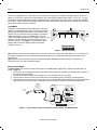
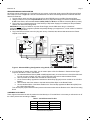
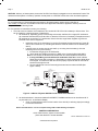
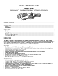
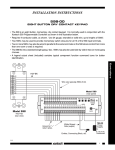
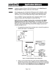
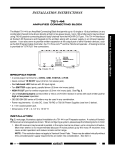
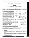
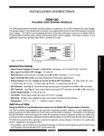
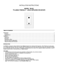
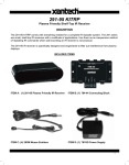
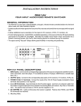
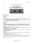
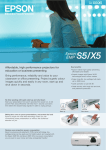
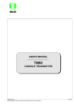
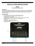
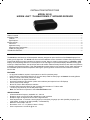
INSTALLATION INSTRUCTIONS MODEL 291-95 HIDDEN LINK™ “PLASMA FRIENDLY” INFRARED RECEIVER TABLE OF CONTENTS Table of contents ............................................................................................................................................................. 1 INTRODUCTION ............................................................................................................................................................. 1 Features ...................................................................................................................................................................... 1 Specifications .............................................................................................................................................................. 1 INSTALLATION ............................................................................................................................................................... 2 Placement ................................................................................................................................................................... 2 Application wiring......................................................................................................................................................... 2 Advanced wiring configuration...................................................................................................................................... 3 3.5Mm mini plug pinout ................................................................................................................................................ 3 TROUBLE SHOOTING .................................................................................................................................................... 4 INTRODUCTION The 291-95 is a small shelf-top infrared repeater assembly designed to reject interference from Plasma Displays from entering the IR signal line. The 291-95 is the first non fixed-installation version of Xantech’s Plasma Series IR product line. These Small IR Receivers are intended to be placed on a shelf, ledge or mantel in close proximity of a Plasma or LCD Display. Its small package allows it to even be placed on the top ledge of most Plasma Displays. Besides showing great immunity to Plasma emissions, the 291-95 (as wells as all Xantech Plasma-Friendly Receivers) work well in the presence of Sunlight and Fluorescent lighting. Their wide-bandwidth reception allows it to be used with a much wider assortment of IR Controllable products than the competition assuring the ‘job will get done’ the first time around without un-wanted service calls. FEATURES • No physical installation required. Can be placed on shelf for quick/easy setup • Quick-Connect 3.5mm Stereo Mini Plug on 7ft. (213.36cm) cable for direct plug-in to Xantech Connecting Blocks • Works in normal 3-wire mode (12VDC, IR, GND) • Red Talkback LED for System Verification • Improved Fluorescent Light rejection (under most conditions) and rejection from LCD Displays • Can be used in Direct Sunlight • Built in RF Grid for EMI interference reduction • Includes CB12 Connecting Block for easy connection and extension of 7' ribbon cable • 7 units may be powered by one 781RG power supply Note: The 291-95 will not operate in 2-wire Phantom Power mode SPECIFICATIONS • Infrared modulation frequency bandwidth: 30 - 100 kHz • Reception range: up to 55 feet (17M), depending on local conditions • Reception angle: 55 degrees off axis for 50% range reduction • Cable requirements: 3-conductor. Use 24 gauge up to 200' (61M), 22 gauge up to 600' (182.5M), 20 gauge up to 1000' (305M), 18 gauge up to 2000' (610KM) -- unshielded OK) • Maximum current output: 100 mA • Dimensions: 3 1/4" x 1" x 2" (83mm x 26mm x 51mm) • Power requirements: 12 volts DC @ 20 mA Page 2 Model 291-95 INSTALLATION These units, equipped with a 7-foot cable and 3.5 mm stereo mini plug, are intended to be plugged directly into the "IR RCVR" or "AUX" jack on Xantech Connecting Blocks, such as the CB12(included), CB60, 789-44, 791-44, etc. The 29195 should be used in installations where the connecting block is within reach of the 7-foot cable -- such as when installing the 291-95 in a cabinet where the controlled equipment is behind closed doors otherwise the included CB12 Connecting Block can be used to extend the distance. PLACEMENT Placement of the IR Receiver does matter when used in the presence of a Plasma Display. Ideally it should be placed at areas around the Display with the front of the receiver flush with the front of (or set back from) the Display. If the 291-95 needs to be placed in front of the display (such as on an adjacent side wall perpendicular to the display), make sure it is placed at a location at least 45 degrees off axis from the corners of the unit – see Figure 1. The presence of Direct Sunlight and Fluorescent Lighting should not effect the reception of this unit. PLASMA DISPLAY 45° 45° Figure 1 – 291-95 Placement Note: Plasma interference can be reflected off of any item it comes into contact with within approx. 3 ft. from the front of the display. Keeping this in mind, make sure that the 291-95 is free of any obstruction that might reflect back into the receiving eye. Note: While this unit shows strong rejection to standard 50/60Hz ‘ballasted’ fluorescent lighting, it is still prone to interference from CFL style Fluorescent lighting. APPLICATION WIRING A typical system, with a 291-95, 781RG Power Supply and 283M Emitter plugged into a 789-44 Connecting Block, is shown in Figure 3: 1. Plug in the 2.1mm Coaxial power plug of the 781RG Power Supply (not included) into the jack labeled 12VDC on the 789-44 Connecting Block. 2. Plug the AC end of the 781RG power Supply into an ‘un-switched’ 120v AC Line outlet. 3. Plug the 3.5mm stereo mini plug from the 291-95 into the IR RCVR input on the 789-44 Connecting Block 4. Plug in the Emitters 3.5mm mono mini plug such as any of the 282, 284, 283 and 286 series into the jacks labeled EMITTERS on the 789-44 and affix the opposite end to the IR Sensor Window of the controlled equipment. 291-95 Hidden Link Plasma-Friendly IR Receiver Hand Held Remote 781RG Satellite Receiver Power Supply To 120 V AC (unswitched) 283M Emitter 789-44 Connecting Block STATUS IR IN EMITTERS 789-44 GND CONNECTING BLOCK 12VDC +12 VDC VCR 283M Emitter AV Receiver ® IR RCVR 283M Blink-IR Mouse Emitter Equipment Rack Figure 2 - Typical System Layout using 291-95, 789-44, 781RG, and 283M Emitters © 2004 Xantech Corporation Model 291-95 Page 3 ADVANCED WIRING CONFIGURATION 291-95 may also be used where the 7-foot lead is not long enough. In this case, simply use the CB12 Connecting Block as a “break-out” block. In Figure 4, a 291-95 is extended down to a 789-44 Connecting Block and combined with other Xantech IR Receivers. 1. Plug the 3.5mm stereo mini plug from the 291-95 into the IR RCVR input on the CB12 Connecting Block. 2. Using 3-Conductor wire (refer to Specifications section for proper Wire Gauge) connect the terminals labeled V G S of the CB12 to the terminals labeled +12VDC, GND, and IR IN on the 789-44 Connecting Block (or other). 3. Plug in the 2.1mm Coaxial power plug of the 781RG (or 782) Power Supply (not included) into the jack labeled PWR on the 789-44 Connecting Block. CAUTION! Do not plug in a 781RG or any other Power Supply into the CB12 when using in a “break-out” configuration. This will put 2 supplies in parallel and possibly damage your equipment. If a ‘local’ emitter is needed on the CB12, see Step 5 below. 4. Plug in the Emitters 3.5mm mono mini plug such as any of the 282, 284, 283 and 286 series into the Emitter Outputs on the 789-44. ROOM 2 ROOM 3 291-95 +12V (See Text) X 780-10 ® Hand Held Remote J-BOX RECEIVER Plasma-Friendly IR Receiver X IR OUT CB12 GND Connecting Block +12 VDC 780-10 J-Box IR Receiver IR OUT GND PWR OUT IR RCVR Power Supply Satellite Receiver 282M +12V 789-44 Connecting Block GND IR OUT V G S To 120 V AC (unswitched) 782-00 Smart Pad STATUS IR IN ® IR RCVR IR Receiver Emitter AV Receiver EMITTERS 789-44 GND 480-30 CONNECTING BLOCK 12VDC 282M +12 VDC 3-Conductor Room-to-Room Cable 24 to 18 gauge (unshielded OK) Mouse Emitter VCR 283M Blink IR Emitter 286M Dual Blink IRs (to other controlled devices) MAIN ROOM 1, EQUIPMENT CABINET, ETC. Figure 3 - Advanced Wiring Configuration using 291-95, CB12, 789-44, 781RG and multiple 286M’s 5. If a local Emitter is needed on the CB12, you will need to place a 470 Ohm Resistor in Series with the Signal Output on the CB12. To wire in this fashion: a. Cut a standard Mouse Emitter (282M or 283M) approximately 12 inches from the 3.5mm Mono Mini Jack. You will now have 2 cables; one with a 3.5mm Mono Mini Jack and one with the Mouse Emitter. b. Wire the 2 leads of the Mono Mini Jack side to a terminal Strip. c. On the Terminal Strip, opposite the lead with the White Stripe (Signal) connect one side of the 470 Ohm Resistor. d. Wire the other side of the resistor to the lead with the White Stripe on the Mouse Emitter. e. Connect the Black Wire of the Mouse Emitter to the Terminal Strip opposite the Black Wire (GND) from the 3.5mm Mono Mini Jack. This will keep the proper load balance and prevent miscommunication with the Emitters on the 789-44 Connecting Block. 3.5MM MINI PLUG PINOUT There might be times when the 291-95 needs to be wired directly to a Terminal Block. In that case you will need to cut off the 3.5mm jack and wire according to Table 1. Table 1 - 291-95 Connector Pin-Out PLUG TIP RING SLEEVE CABLE LEADS WHITE BLACK RED CIRCUIT ITEM IR OUT GROUND +12V © 2004 Xantech Corporation Page 4 Model 291-95 CAUTION: With any of these systems, be sure the 781-RG Power Supply is plugged into an un-switched AC outlet. This maintains the 490 system in "stand-by" operation so that power-on commands can be sent to the controlled equipment. TROUBLE SHOOTING For a complete listing of Trouble Shooting techniques for IR based systems, please visit our Web Site at www.xantech.com and click on PRODUCTS and then select Application Advisories. Application Advisory AA-03 is a complete IR Trouble Shooting Guide. For non-operation or intermittent control try the following: 1. The most common indication of IR interference is if the 291-95’s TB LED is ON constantly or flickers often. This can be caused by numerous sources of Interference: a. RF Interference: Depending upon the surrounding environment and Wire Run Lengths, RF interference can cause the Talk Back LED to Flicker often or cause the LED to be on Constantly. Examples sources of RF Interference can be from TV Transformers, Dimmer Circuits, Large Power Supplies, High Current Electrical Lines, and PC Equipment. • Isolate the source of the interference by turning off suspected sources and seeing if proper IR control can be achieved. Try relocating the 291-95 to minimize effects from the interfering RF source. • If the RF source is coupling into the wire itself, try re-routing the wire isolating it from the interfering source or try the following: 1. Increase the wire gauge for the IR Receiver 2. Use a shield as a DRAIN connecting it to GND on the Connecting Block side ONLY. Note: Do not connect the Shield at both ends as this can cause Capacitive interference. 3. If using CAT5 Wire you must utilize all 8 conductors of the wire. Use all 4 White Stripe wires for the GND connection, 2 Solid Wires for 12VDC and the last 2 Solid Wires for IR Signal. This will ensure that all lines are properly coupled to GND to minimize RF interference through the wire. 4. Connect a GND wire from the Connecting block terminal to an electrical GND (See Figure 4 below). Use 16AWG Wire from GND on the Connecting Block to a cold water GND. 781RG Satellite Receiver Power Supply To 120 V AC (unswitched) 291-95 Hidden Link Plasma-Friendly IR Receiver +12 VDC 789-44 STATUS IR IN EMITTERS GND ® IR RCVR CONNECTING BLOCK 12VDC Hand Held Remote 283M Emitter 789-44 Connecting Block VCR 283M Emitter AV Receiver 283M Blink-IR Mouse Emitter Equipment Rack Figure 4 – Addition of System GND Wire for RF Interference Reduction b. As mentioned above in the section labeled PLACEMENT, PLASMA interference can be reflected off of any item within 3 ft. of the Plasma Display. • Check for reflected items and move the location of the 291-95 (or reflecting object) accordingly to minimize interference. • Please visit www.xantech .com for a complete listing of IR Trouble Shooting Techniques! XANTECH CORPORATION 13100 Telfair Avenue, Sylmar CA 91342-3829 phone 818.362.0353 • fax 818.362.9506 Part No. 08905030 Rev A 09-07-04 © 2004 Xantech Corporation