1
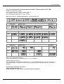
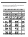
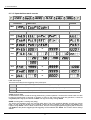
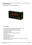
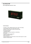
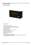
User manual M1 – Multi-function device
Measuring inputs: Direct voltage, Direct current, Pt100(0), Thermocouple,
Frequency, Rotation speed, Counter
Technical features:
• red display of -1999…9999 digits (optional: green, orange or blue display)
• minimal installation depth: 25 mm without plug-in terminal
• digit height 14 mm
• far range power supply 100-240 VAC or standard supply 230 VAC or 24 VDC
• display adjustment via factory presetting or directly on the sensor signal
• min/max-memory
• 5 adjustable supporting points
• display flashing at threshold value exceedance/undercut
• Tara-function
• sliding averaging
• programming interlock via access code
• protection class IP65 at the front
• pluggable screw terminal
• accessories: PC-based configuration software incl. CD and USB-adapter for devices without
keypad and for a simple adjustment of standard devices.
M1_1UGB.pdf update: 13.05.2015
96x48
Identification
STANDARD-TYPES
ORDER NUMBER
Multi-function measuring inputs
Housing size: 96x48 mm
M1-1UR4B.000X.S70AD
M1-1UR4B.000X.570AD
M1-1UR4B.000X.770AD
Options – break-down order key:
M 1- 1 U R 4 B. 0 0 0 X. S 7 0 A D
Standard type M-Line
Dimension
D physical unit
Installation depth
38 mm incl. plug-in terminal
1
Version
A A
Housing size
96x48x25 mm (BxHxD)
1
Switching points
0 without
Display type
Multi-function display
U
Protection class
1 without keypad, operation on the back
via PC software PM-TOOL
Display colours
Green
G
Red
R
7 IP65/pluggable terminal
Orange
Y
Voltage supply
Blue
B
5 230 VAC 50/60 Hz
7 24 VDC galv. isolated
S 100-240 VAC / DC +/-10%
Number of digits
4-digit
4
Measuring input
X Voltage, Current, Temperature,
Digit height
14 mm
B
Interface
without
Frequency
Analog output
0
0 without
Sensor supply
0 without
Please state physical unit by order, e.g. mbar
Contents
1.
Brief description
3
2.
Assembly
3
3.
Electrical connection and connection examples
4
3.1. Terminal pin assignment
4
3.2. Connection examples
4
3.2.1. Voltage / Current
4
3.2.2. Pt100 / Pt1000 / Thermocouple
5
3.2.3. Frequency / Rotation speed
5
3.2.4. Counter
6
4.
5.
6.
Description of function and operation
7
4.1. Operating and display elements
7
4.2. Programming software PM-TOOL
7
Setting-up the device
8
5.1. Switching on
8
Parameterisation
8
6.1. Selection of input signal, Type
8
6.1.1. Voltage/Current, Volt, AMPE
9
Setting of the final and inital value, End, Enda, offs, offa
10
Setting of the decimal point, Dot.A
10
Zero point slowdown of the input signal, zero
10
Taring value, tara
10
Overflow/underflow behaviour, over
10
Input of supporting points for linearisation of the measuring signal, spc.A
10
6.1.2. Pt100, Pt1000, Thermocouple, pt.se, ther
11
Temperature device in °C/°F, unit
11
Impedance matching, offs
11
6.1.3. Pulse measuring, impu
12
6.1.3.1. Frequency, freq
12
Pulse triggering, i.typ
13
Range of frequency, rang
13
Filter, filt
13
Adjustment of final and initial value, end, endf, offs, offf
14
Adjustment of the decimal point, dot.F
14
Taring value, tara
14
Input of supporting points for linearisation of the measuring signal, spc.F
14
6.1.3.2. Rotation speed, turn
14
Pulse triggering, i.typ
15
Filter, filt
15
Pulse per revolution, ppt
15
Time base, time
15
Adjustment of the decimal point, dot
15
1
Contents
6.1.3.3. Counter upwards/downwards, Co.up, Co.dn
16
Pulse triggering, i.typ
16
Counter base / Input signal, co.ba
16
Wing, edge
16
Prescaler, pres
17
Display value and pulse final numerical value, end, end.c
17
17
6.2. General device parameter
Adjustment of measuring time, sec
17
Adjustment of the sliding average value, glm
18
Presentation of initial/final value in the display, di.hi, di.lo
18
Allocation of functions onto the navigation keys, tast
18
Display flashing at threshold value exceedance/undercut, flas
18
18
6.3. Alarm parameter
Limit value behaviour, a1.fu, a2.fu
19
Alarm flashing in case of limit value errors, a1.er, A2.er
19
Adjustment of the switching threshold, a1.li, a2.li
19
Adjustment of the hysteresis, a1.hy, a2.hy
19
Upper limit value, a1.lo, a2.lo
19
Lower limit value, a1.hi, a2.hi
19
Drop off delay, a1.of, a2.of
19
Activation delay, a1.on, a2.on
19
6.4. Safety parameter – locking of the parameterisation
7.
20
Assignment of individual numerical codes, Code
20
Activation/Deactivation of the programming interlock, run
20
20
Reset to default values
Setting back the parameter onto delivery condition
8.
Technical data
21
9.
Safety advices
23
10.
Error elimination
24
2
1. Brief description / 2. Assembly
1. Brief description
The panel instrument M1-1U is a 4-digit device for measuring of different kind of measuring signals such as
direct voltage/direct current, temperature and frequency and a visual limit value monitoring via the display.
The configuration happens via three front keys or via the optional PC-software PM-TOOL. An integrated
programming interlock prevents unrequested changes of the parameter and can be released again via an
individual code. The electrical connection happens on the rear side via plug-in terminals.
Selectable functions like e.g. the recall of the min/max-value, Tara-function, averaging, a direct change of
the limit value in operating mode and additional measuring supporting points for linearisation complete the
concept of a modern device.
2. Assembly
Please read the Safety instructions on page 23 before installation and keep this user manual for future reference.
3,0
48,0
Se
alin
g
96
,0
,0
pth
38
de inal
n
o
ti
erm
alla g-in t
t
s
In plu
l.
inc
Gap for physical
unit
1.
2.
3.
After removing the fixing elements, insert the device.
Check the seal to make sure it fits securely.
Click the fixing elements back into place and tighten the clamping screws by hand. Then use a
screwdriver to tighten them another half a turn.
CAUTION! The torque should not exceed 0.1 Nm!
3
3. Electrical connection
3. Electrical connection
3.1. Terminal pin assignment
Type M1-1UR4A.000X.S70AD – supply 100-240 VAC, DC ±10%
Type M1-1UR4A.000X.570AD – supply 230 VAC 50/60 Hz
Type M1-1UR4A.000X.770AD – supply 24 VDC galv. isolated
3.2. Connection examples
Below please find some connection examples, which demonstrate some practical applications:
3.2.1. Current / Voltage
2-wire sensor 4…20 mA
2-wire sensor 4…20 mA with external
voltage source
3-wire sensor 0/4…20 mA
3-wire sensor 0/4…20 mA with external
voltage source
4
3. Electrical connection
3-wire sensor 0/1/2…10 V
3-wire sensor 0-1/2…10 V
with external voltage supply
4-wire sensor 0/1/2…10 V, 50 mV
3-wire sensor 0-1/2…10 V, 50 mV
with external voltage supply
3.2.2. Temperature
Pt100 wire
Pt1000 2-wire
Thermocouple
5
3. Electrical connection
3.2.3. Frequency / Rotation speed
Encoder with TTL-output
Encoder with external voltage source and
TTL-output
Encoder with PNP-output
Encoder with NPN-output and required external
resistance
Encoder with NPN-output
Encoder with external voltage source and
NPN-output
Encoder with NPN-output and necessary
external resistance
Encoder with external voltage source, NPNoutput and necessary external resistance
6
3. Electrical connection
Encoder with PNP-output and external
resistance circuit
Encoder with external supply, PNPoutput and external resistance circuit
3.2.4. Counter
If the device is used as counter, please use the connection examples for frequency/rotation speed and follow
the examples given below for a performed reset input:
Manual setting back via external feeler
7
4. Description of function and operation
4. Description of function and operation
4.1. Operating and display elements
The device comes with three keys, which are used for parameterisation of the device and whose deposited
functions can be called up during operation. Functions, that can be adjusted or changed are always signalised
by a flashing of the display. Adjustments that were made in the „Parameterisation level“ are always confirmed
with [P] and thus saved. The device saves however automatically all adjustments and changes back into
operating mode, if no more key actuation takes place within 10 seconds.
Key symbol
Function in operating mode
Function at parameterisation
Program key [P]
Change the parameterisation with program
key [P].
Change into a lower parameterisation
-level or to deposited values.
Minus key [▼]
Depending on adjusted key functions, use
the minus key [▼] for calling up the minvalue or changing a lower limit value.
Change between parameter and
changing of parameter within the
value level.
Plus key [▲]
Depending on adjusted key functions, use
the plus key [▲] for calling up the minvalue or changing a lower limit value.
Change between parameter and
changing of parameter within the
value level.
A switched-on relay or an activated switching point will be reported optically by a flashing of the respective
switching point LED next to the 7-segment display. A display over-/underflow is displayed by four bars „- - - -„.
Example: Setting up the device parameter, e.g. selection of the input signal
Parameter
Choice
Example: Setting up numerical values, e.g. final value of measuring range
Numerical values are adjusted from the smallest to the highest digit with [▲] [▼] and confirmed digit per digit
with [P]. A minus sign can only be adjusted on the leftmost digit. After the last digit, the display changes back
into menu-level.
4.2. Programming via configuration software PM-TOOL MUSB4:
The software comes on CD incl. an USB-cable with a device adapter. The connection happens via a 12-pole
micromatch connector plug on the back and the PC is connected via an USB connector plug.
System requirements:
PC with USB interface
Software:
Windows XP, Windows Vista
With this tool the device configuration can be created, skipped and saved on the PC. Via the easy to handle
program surface the parameter can be changed, whereat the mode of operation and the possible selection
options can be preset via the program.
CAUTION!
During parameterisation with a connected measuring signal, make sure that the measuring signal has no mass
supply to the programming plug. The programming adapter is galvanically not isolated and directly connected
with the PC. Via polarity of the input signal, a current can discharge via the adapter and destroy the device as
well as other connected components!
8
5. Setting up the device / 6. Parameterisation
5. Setting up the device
5.1. Switching on
Once the installation is complete, start the device by applying the voltage supply. Check beforehand once
again that all the electrical connections are correct.
Starting sequence
For 1 second during the switching-on process, the segment test (8 8 8 8 8) is displayed, followed by an
indication of the software type and, after that, also for 1 second, the software version. After the start-up
sequence, the device switches to operation/display mode.
6. Parameterisation
6.1. Selection of the input signal: type
During the type adjustment, an allocation of the input version takes place. Here, one can select between 5
input types: Voltage, Current, Pt100(0), Thermocouple and Pulse signal.
Selection measuring
signal
Voltage
s.page 10
Current
s.page 10
Pt100(0)
s.page 12
Thermocouple
s.page 12
Pulse input
s.page 13
Measuring signal
special parameter
General device
parameter
Measuring time, sliding averaging,
presentation of initial and final value in the
display, key function, display flashing
See page 18
Alarm parameter
Limit value behaviour, report limit value,
threshold, hysteresis, delay
See page 19
Safety parameter
Lock / release of parameterisation
See page 21
9
6. Parameterisation
6.1.1. Device parameter for the allocation of voltage/current signals: VoLT, AMPE
VoLT: 4 voltage signals are available: 0-10 V, 0-2 V, 0-1 V and 0-50 mV
AMPE: Choose between the following signals: 0-20 mA and 4-20 mA
Parameter
Menu item
Default
Menu item
Default
VoLt
AMPE
Parameter
End
to
OFFS
to
dot.A
to
EndA
to
OFFA
to
tArA
to
ZErO
to
OUEr
SPC.A
to
dIS.1
to
InP.1
to
dIS.2
to
InP.2
to
dIS.3
to
10
6. Parameterisation
Parameter
Menu item
Default
InP.3
to
dIS.4
to
InP.4
to
diS.5
to
InP.5
to
End / OFFS: Upper range value/lower range value
By use of this pair of values, the desired display value can be allocated to the measuring signal.
dot.A: Comma / decimal place
Determine the decimal representation of the display value with the decimal point. It is used for the adjustment
of the limit values, too.
EndA / OFFA: Rescale the measuring input values
With this function the final value/initial value can be rescaled to e.g. 19.5mA/3.2mA without application of the
measuring signal.
tArA: Setting up the Tara value / Offset value
The preset value is added to the linearised value. So the characteristic line can be shifted by the selected
amount.
ZErO: Zero-point slowdown
Here, a range of values around the zero-point can be preset, where the display shows a zero. If e.g. a 10 is
adjusted, the display would show a zero within a range of value of -10 to +10 and continue below with
-11 and above with +11.
OVEr: Overflow and underflow behaviour
The overflow/underflow of the measuring input will be signaled by 4 horizontal bars at the top respectively by 4
bars at the bottom. Exception is input type „4-20“ (mA), where a measurand smaller than 1 mA can already be
valuated as underflow. This shall indicate a sensor failure.
no
No additional check of the range takes place. By leaving the display range, the display remains
on the smallest value „dI.Lo“ respectively highest value „dI.HI“.
AdC
At exceedance/undercut of the display range „dI.Lo“ / „dI.HI“ over-/underflow will be displayed.
rAnG
The measuring signal needs to be exactly in the preset measuring range „EnD“/“OFFS“, so
that an overflow will not be detected. The display range and transformer range will be
monitored additionally.
5 Pr
The measuring signal is monitored over ± 5% of the adjusted measuring range. The display
range will be monitored additionally.
10 Pr
The measuring signal is monitored over ± 10% of the adjusted measuring range. The display
range will be monitored additionally.
SPC.A: Number of additional supporting points
To linearise nonlinear sensor values, five additional supporting points can be defined for the initial and final
value. Only the activated supporting point parameters are shown.
dIS1…dIS5: Display values for supporting points
Under this parameter supporting points are defined on a value basis.
INP1…INP5: Analog values for supporting points
The supporting points are always preset according to the selected input signal ma/V. Here, desired analog
values can be freely adjusted in ascending order.
11
6. Parameterisation
6.1.2. Device parameter for the allocation of Pt100(0), Thermocouple: Pt.SE, THEr
Pt.SE: Three types are available:
Pt.Lo: Pt100 3-wire -50.0…200.0°C / -58.0…392.0°F
Pt.Hi: Pt100 3-wire -200…850°C / -328…1562°F
Pt.tH: Pt1000 2-wire -200…850°C / -328…1562°F
tHEr: Select between: Thermocouple types L, J, K, B, S, N, E, T, R
Parameter
Menu item
Default
Menu item
Default
Menu item
Default
Pt.SE
Parameter
tHEr
Parameter
UnIt
OFFS
to
to
UnIt: Type of temperature metering
Chose, if the temperature shall be displayed in °C or °F with UnIt.
OFFS: Impedance matching
The value alignment at a temperature measuring in °C can be adjusted between -20,0 and +20,0 and for a
later measurement in °F between -36 and +36. If the measuring type is changed later, the value will be
rounded.
General device parameter see page 18
Alarm parameter see page 19
Safety parameter for lock / release of parameterisation see page 21
12
6. Parameterisation
6.1.3. Device parameter for the allocation of pulse signals: IMPU
FrEq: Frequency measuring of TTL-signals, PNP/NPN-sensors.
tUrn: Rotation speed measurement (simplified adjustment option) of TTL-signals, PNP/NPN-sensors.
A flow rate can be scaled with this function, too.
CO.up: Counter input (upwards) for TTL-signals, PNP/NPN-sensors.
CO.on: Counter input (downwards) for TTL-signals, PNP/NPN-sensors.
6.1.3.1. Frequency measurement
Parameter
Menu item
Default
Menu item
Default
IMPu
Parameter
I.tYP
rAnG
FILt
End
to
OFFS
to
dot.F
to
End.F
to
OFF.F
to
tArA
to
SPC.F
to
dIS.1
to
InP.1
to
dIS.2
to
13
6. Parameterisation
Parameter
Menu item
Default
InP.2
to
dIS.3
to
InP.3
to
diS.4
to
InP.4
to
diS.5
to
InP.5
to
I.tYP: Pulse signal
There a three modes for the triggering of the pulse input:
ttL
Active TTL-signals with approx. 0.8 V lower and approx. 2 V upper threshold.
nPn
Passive switching contact, which operates the internal pull-up depending on the rate.
PnP
Active sensor output. A pull-down is operated in the device.
rAnG: Selection of the frequency range
A selection of four frequency ranges is available:
9.999
0…9,999 Hz (automatic software filter on 100 Hz/5ms)
99.99
0…99,99 Hz (automatic software filter on 500 Hz/5ms)
999.9
0…999,9 Hz
9999
0…9999 Hz (approximate 10 kHz)
FILt: Limitation of the pulse length
For contact bounce suppression of mechanical contacts via selection of the filter frequency.
no
no particular evaluation of the pulse length
2
2 Hz with pulse-duty factor 1:1 => minimal pulse length 250 ms
5
5 Hz with pulse-duty factor 1:1 => minimal pulse length 100 ms
10
10 Hz with pulse-duty factor 1:1 => minimal pulse length 50 ms
20
20 Hz with pulse-duty factor 1:1 => minimal pulse length 25 ms
50
50 Hz with pulse-duty factor 1:1 => minimal pulse length 10 ms
100
100 Hz with pulse-duty factor 1:1 => minimal pulse length 5 ms
500
500 Hz with pulse-duty factor 1:1 => minimal pulse length 1 ms
14
6. Parameterisation
End / OFFS: Upper range value/lower range value
By use of this pair of values, the desired display value can be allocated to the measuring signal.
dot.F: Comma / decimal place
Determine the decimal representation of the display value with the decimal point. It is used for the adjustment
of the limit values, too.
End.F / OFF.F: Rescale the measuring input values
With this function the final value/initial value ca be rescaled without application of the measuring signal.
tArA: Setting up the Tara-/Offset value
The preset value is added to the linearised value. So the characteristic line can be shifted by the selected
amount.
SPC.F: Number of additional supporting points
To linearise nonlinear sensor values, five additional supporting points can be defined for the initial- and final
value. Only the activated supporting point parameter are shown.
dIS1…dIS5: Display values for supporting points
Under this parameter supporting points are defined on a value basis.
INP1…INP5: Analog values for supporting points
The supporting points are always preset according to the selected input signal ma/V. Here, desired analog
values can be freely adjusted in ascending order.
6.1.3.2. Rotation speed measurement
As more than 80% of frequency measurement applications are referring to a rotation speed, there is a
simplified adjustment mode available via type „Turn“. A flow rate can be scaled with this function, too.
Parameter
Menu item
Default
Menu item
Default
IMPu
Parameter
I.tYP
FILt
PPt
to
tIME
dot
to
15
6. Parameterisation
I.tYP: Pulse signal
There are three modes for the triggering of the pulse input:
ttL
Active TTL-signals with approx. 0.8 V lower and approx. 2 V upper threshold.
nPn
Passive switching contact, which operates the internal pull-up depending on the rate.
PnP
Active sensor output. A pull-down is operated in the device.
FILt: Limitation of the pulse length
For contact bounce suppression of mechanical contacts via selection of the filter frequency:
no
No particular evaluation of the pulse length
2
2 Hz with pulse-duty factor 1:1 => minimal pulse length 250 ms
5
5 Hz with pulse-duty factor factor 1:1 => minimal pulse length 100 ms
10
10 Hz with pulse-duty factor factor 1:1 => minimal pulse length 50 ms
20
20 Hz with pulse-duty factor 1:1 => minimal pulse length 25 ms
50
50 Hz with pulse-duty factor 1:1 => minimal pulse length 10 ms
100
100 Hz with pulse-duty factor 1:1 => minimal pulse length 5 ms
500
500 Hz with pulse-duty factor 1:1 => minimal pulse length 1 ms
PPt: Pulse per turn
With this parameter the number of pulse per turn can be entered directly. It generally works with sprockets and
their number of sprockets, incremental encoder and their resolution or glands with a number of boreholes. For
simple flow meter with impeller it is only neccessary to enter the number of pulse per liter or cubic metre.
tIME: Time base
In general the time base for rotation speed is always set on „MIn“, it can of course be changed into seconds or
hours.
dot: Comma / decimal place
Determine the decimal representation of the display value with the decimal point. A rotation speed with up to 3
positions after decimal point can be displayed, if they are small enough.
Example: Rotation speed measurement
The rotation speed of a roller in a steel works needs to be displayed in turns/minute with one position after
decimal place. The rotational speed will be recorded via a perforated disc with 18 holes, positioned in an angle
of 20°. The maximum rotation speed of the roller is 60 turns/minute. Like this, adjust for example FILt = 100;
PPt = 18; tIME = MIn; dot = 0.0. The difficulty with the adjustment of the filter is to calculate the pulse length
precisely.
16
6. Parameterisation
6.1.3.3. Upwards/downwards counter
Parameter
Menu item
Default
Menu item
Default
IMPu
Parameter
In.tY
Co.bA
EdGE
PrES
to
FILt
End
to
End.C
to
dot
to
I.tYP: Pulse signal
There a three modes for the triggering of the pulse input:
ttL
Active TTL-signals with approx. 0.8 V lower and approx. 2 V upper threshold.
nPn
Passive switching contact, which operates the internal pull-up depending on the rate.
PnP
Active sensor output. A pull-down is operated in the device.
Co.bA: Counter base
As standard the device records incoming pulses during counter operation. However the counter basis can also
be used as system time in seconds or minutes. In doing so the pulse input turns into gate time, it counts at
wing PoSI (HIGH-signal) and stands at LOW. The logic is contrary at wing nEGA.
EdGE: Counting start / counting end (wing)
The active wing declares when the counting takes place. The pulse recording PuLS is choosen as counter
basis, via this it will be declared if the internal counter will be increased by the positive wing PoSI or the
negative wing nEGA. If time is taken as time basis, then the active-triggering/HIGH-triggering will be selected
with PoSI and the passive triggering/LOW-triggering will be selected with nEGA. The counter reset is always
statical.
17
6. Parameterisation
PrES: Prescaler
A prescaling in the device happens via the prescaler, so even large pulse numbers like e.g. 5.000.000 can be
recorded by the device. Only the prescaled value will be included for the scaling.
FILt: Limitation of the pulse length
For contact bounce suppression of mechanical contacts via selection of the filter frequency:
No particular evaluation of the pulse length
no
2
2 Hz with pulse-duty factor 1:1 => minimal pulse length 250 ms
5
5 Hz with pulse-duty factor factor 1:1 => minimal pulse length 100 ms
10
10 Hz with pulse-duty factor factor 1:1 => minimal pulse length 50 ms
20
20 Hz with pulse-duty factor 1:1 => minimal pulse length 25 ms
50
50 Hz with pulse-duty factor 1:1 => minimal pulse length 10 ms
100
100 Hz with pulse-duty factor 1:1 => minimal pulse length 5 ms
500
500 Hz with pulse-duty factor 1:1 => minimal pulse length 1 ms
End, End.C: Display terminal value and pulse terminal value
The display value can be freely linearised via the prescaled pulse number. For it the number of desired pulses
will be allocated to a display value. The zero-point cannot be prescaled. At a backwards counter End and
End.C serve as start value. For the absolute counter threshold values, the adjustments of dI.HI and dI.Lo are
used. By reaching them, all digits that reached this value are flashing, what equates an underflow/overflow.
General device parameter see page 18
Alarm parameter see page 19
Safety parameter for lock / release of parameterisation see page 21
6.2. General device parameter
Parameter
Menu item
Default
SEC
to
GLM
to
dI.HI
to
dI.Lo
to
tASt
FLAS
SEC: Measuring time
Adjustement of basis measuring time respectively of the frequency filter for a relief of the measurand. This
filter value is adjustable from 0.01…2.00 seconds. At pulse measurement, the value can be selected up to
0.00, so that the identification runs on maximum speed.
18
6. Parameterisation
GLM: Sliding averaging
Besides the measuring time, a sliding averaging of 1…20 values can be activated, too. Here, no seperate
emphasis between the past values is taking place. At GLM = 1 the sliding averaging is switched off.
dI.Lo, dI.HI: Presentation of start/terminal value in the display
For overflow evaluation the measuring range and the optional selected overflow (OVEr) behaviour are
evaluated. In addition this range can be limited by the parameter dI.HI and dI.Lo.
tASt: Allocation (deposit) of key functions
For operating mode either a min/max-value monitoring or a limit value correction on the navigation keys can
be deposited here. If the min/max memory is activated by EHtr, the measured min/max-values will be saved
during operation and can be recalled via the navigation keys [▲] [▼]. At restart of the device, all values are
lost. If the limit value correction AL.LI is selected, limit values can be changed during operation, without
interfere with the operating procedure. If no is adjusted, the navigation keys [▲] [▼] are without any function
in the operating mode.
FLAS: Display flashing at threshold value exceedance/undercut
A display flashing can be added as additional alarm function either to the first limit value (select: AL-1), to the
second limit value (select: AL-2) or to both limit values (select: AL-12). With no (factory settings), no flashing
is allocated.
6.3. Alarm parameter
Parameter
Menu item
Default
AI.Fu
AI.Er
AI.LI
to
AI.HY
to
AI.HI
to
AI.Lo
to
AI.oF
to
AI.on
to
A2.Fu
A2.Er
A2.LI
to
19
6. Parameterisation
Parameter
Menu item
Default
A2.HY
to
A2.HI
to
A2.Lo
to
A2.oF
to
A2.on
to
A1.Fu, A2.Fu: Limit value behaviour
Change between the different working types of switching outputs by using the functional principle.
If Ax.Fu = oFF was selected, the relevant switching point parameter will not be displayed.
oFF
The switching point is without function and relevant parameter will not be displayed (Default
status).
On
The switching point is switched on during measuring operation and corresponding parameter
(except Ax.Er and Ax.tY) will not be displayed.
HI-LI
Switch at threshold value exceedance.
Lo.LI
Switch at threshold value undercut.
rAnG
Switch within the preset range.
Out.r
Switch outside the preset range.
A1.Er, A2.Er: Alarm flashing in case of limit value errors
on
oFF
Display flashes in case of limit value errors.
Optical alarm not active (no flashing in case of limit value errors).
A1.L1, A2.L1: Threshold level
Here the threshold level is defined that activates/deactivates an alarm. This parameter will not be recalled if
the window function is used.
A1.HY, A2.HY: Hysteresis
The hysteresis defines a difference to the limit value which defines the delay of an alarm. This parameter will
not be recalled if the window function is used.
A1.HI, A2.HI: Upper limit value
A1.Lo, A2.Lo: Lower limit value
For range functions A1.FU, A2.FU = rAnG or Out.r this value defines the upper/lower limit of the window
function between „-1999…9999“. This parameter will not be displayed with other functional principles. The
functional principle can change between switching point 1 and 2.
A1.oF, A2.oF: Dropout delay
Preset a delayed switching off of 0-5999 seconds for the limit values. The time value will not be saved
permanently and is set back by restart of the device. Furthermore the alarm condition will be detected during
restart, without considering the preset delay.
A1.on, A2.on: On-delay
Preset a delayed switching on of 0-5999 seconds for the limit values. The time value will not be saved
permanently and is set back by restart of the device. Furthermore the alarm condition will be detected during
restart, without considering the preset delay.
20
7. Reset to default values (factory settings)
6.4. Safety parameter for lock/release of parameterisation
Parameter
Menu item
CodE
Default
to
run
CodE: Assignment of an individual numerical code (4-digit number combination, free allocatable)
With assignment of this code (0000 factory settings), all parameter will be locked for the user, if LOC was
selected afterwards under menu item run. By pushing [P] in operating mode for approx 3 seconds, the
message CodE appears in the display. The code needs to be entered before each parameterisation, until the
programming is released with ULoC under run.
run: Activation/Deactivation of programming interlock
Select with [▲] [▼] between deactivated key lock ULOC (factory settings) and activated key lock LOC. The
keypad is locked, if LOC was selected. To get into menu level again, [P] needs to be pushed for 3 seconds in
operating mode. The now appearing CodE (factory settings 0000) needs to be entered with [▲] [▼] and [P]
and releases the keypad. A faulty entry will be displayed with FAIL.
In LOC-mode the device cannot be resetted, which shall additionally secure the regular operation.
7. Reset to default values (factory settings)
To set the device into a defined inital state, there is the possibility to do a reset to the default values. Please
proceed as follows:
Switch off the voltage supply of the device. Push the [P]-key and switch voltage supply on with in-position [P]key. Push the [P]-key until „----“ appears in the display. Due to the reset, default values are charged and used
for further operation. The device is now reset to the delivery state.
ATTENTION!
All application related data are lost!
21
8. Technical data
8. Technical data
Housing
Dimensions
96x48x25 mm (WxHxD)
96x48x38 mm (WxHxD) including plug-in terminal
Panel cut-out
92.0+0.8 x 45.0+0.6 mm
Wall thickness
up to 3 mm
Fixing
screw elements
Material
PC Polycarbonate, black, UL94V-0
Sealing material
EPDM, 65 Shore, black
Protection class
standard IP65 (front panel), IP00 (back side)
Weight
approx. 100 g
Connection
plug-in terminal; wire cross-section up to 2.5 mm2
Display
Digit height
14 mm
Segment colour
red (optional green, orange or blue)
Display range
-1999 to 9999
Limit values
optical display flashing
Overflow
horizontal bars at the top
Underflow
horizontal bars at the bottom
Display time
0.1 to 10.0 seconds
Signal
Measuring range
Measuring span
Resolution
Internal resistance
Voltage
0…10 V
0…12 V
≥ 14 bit
Ri > 100 kΩ
Voltage
0…2 V
0…2.2 V
≥ 14 bit
Ri ≥ 10 kΩ
Voltage
0…1 V
0…1.1 V
≥ 14 bit
Ri ≥ 10 kΩ
Voltage
0…50 mV
0…55 mV
Ri ≥ 10 kΩ
Current
4…20 mA
1…22 mA
Ri = ~125 Ω
Current
0…20 mA
0…22 mA
Ri = ~125 Ω
Pt100-3-wire
-50…200°C
-58…392°F
0.1°C / 0.1°F
Pt100-3-wire
-200…850°C
-328…1562°F
1°C / 1°F
Pt1000-2-wire
-200…850°C
-328…1562°F
1°C / 1°F
Thermo K
-270…1350°C
-454…2462°F
1°C / 1°F
Thermo S
-50…1750°C
-328…3182°F
1°C / 1°F
Thermo N
-270…1300°C
-454…2372°F
1°C / 1°F
Thermo J
-170…950°C
-274…1742°F
1°C / 1°F
Thermo T
-270…400°C
-454…752°F
1°C / 1°F
Thermo R
-50…1768°C
-58…3214°F
1°C / 1°F
Thermo B
80…1820°C
176…3308°F
1°C / 1°F
22
8. Technical data
Signal
Measusing range
Measuring span
Resolution
Thermo E
-270…1000°C
-454…1832°F
1°C / 1°F
Thermo L
-200…900°C
-328…1652°F
1°C / 1°F
Frequency
0…10 kHz
0…10 kHz
0,001 Hz
NPN
0…3 kHz
0…3 kHz
0,001 Hz
PNP
0…1 kHz
0…1 kHz
0,001 Hz
Rotation speed
0…9999 1/min
0…9999 1/min
0,001 1/min
Counter
0…9999 (Prescaler up to 1000)
Pulse input
TTL
HTL/PNP
NPN
Namur
Low <2 V,
High >3 V
Low <6 V,
High >8 V
Low <0.8 V,
High via resistance
Low <1.5 mA,
High >2.5 mA
Reset-input
active <0.8 V
Measuring error
Standard
0.2% of measuring range ± 1 digit
Pt100/Pt1000
0.5% of measuring range ± 1 digit
Thermocouple
0.3% of measuring range ± 1 digit
Accuracy
Reference junction
± 1°C
Drift of temperature
100 ppm / K
Measuring time
0.01…20.0 seconds
Sampling rate
approx. 1/s at thermocouple, approx. 100/s at standard signals
Measuring principle
U/F-conversion
Resolution
approx. 14 bit at 1s measuring time
Output
Interface
Configuration interface for PC-software PM-TOOL with USB-dongle
Power supply
100-240 VAC 50/60 Hz, DC ± 10%
230 VAC 50/60 Hz ≤ 3 VA
24 VDC galvanic isolated ≤ 1 VA
Memory
EEPROM
Data life
≥ 100 years at 25°C
Ambient condition
Working temperature
-20°C…+50°C
Storing temperature
-30°C…+70°C
Weathering resistance
relative humidity 0-85% on years average without dew
EMV
EN 61326
CE-identification
Conformity according to directive 2004/108/EG
Safety standard
According to low voltage directive 2006/95/EG
EN 61010; EN 60664-1
23
9. Safety advices
9. Safety advices
Please read the following safety advices and the assembly chapter 2 before installation and keep
it for future reference.
Proper use
The M1-1U-device is designed for the evaluation and display of sensor signals.
Danger!
Careless use or improper operation can result in
personal injury and/or damage the equipment.
Control of the device
The panel meters are checked before dispatch and sent out in perfect condition. Should there be
any visible damage, we recommend close examination of the packaging. Please inform the
supplier immediately of any damage.
Installation
The M1-1U-device must be installed by a suitably qualified specialist (e.g. with a qualification in
industrial electronics).
Notes on installation
• There must be no magnetic or electric fields in the vicinity of the device, e.g. due to
transformers, mobile phones or electrostatic discharge.
• The fuse rating of the supply voltage should not exceed a value of 6A N.B. fuse.
• Do not install inductive consumers (relays, solenoid valves etc.) near the device and
suppress any interference with the aid of RC spark extinguishing combinations or free-wheeling
diodes.
• Keep input, output and supply lines separate from each other and do not lay them parallel with
each other. Position “go” and “return lines” next to one another. Where possible use twisted pair.
So, the best measuring results can be received.
• Screen off and twist sensor lines. Do not lay current-carrying lines in the vicinity. Connect the
screening on one side on a suitable potential equaliser (normally signal ground).
• The device is not suitable for installation in areas where there is a risk of explosion.
• Any electrical connection deviating from the connection diagram can endanger human life
and/or can destroy the equipment.
• The terminal area of the devices is part of the service. Here electrostatic discharge needs to be
avoided. Attention! High voltages can cause dangerous body currents.
• Galvanically isolated potentials within one complex need to be placed on an appropriate point
(normally earth or machines ground). So, a lower disturbance sensibility against impacted
energy can be reached and dangerous potentials, that can occur on long lines or due to faulty
wiring, can be avoided.
24
10. Error elimination
10. Error elimination
Error description
Measures
1.
The unit permanently
indicates overflow.
• The input has a very high measurement, check the measuring
circuit.
• The display range of 999 respectively the preset measuring
range was exceeded, control the supporting points
respectively the selected input type and signal range. Not all
of the activated supporting points are parameterised. Check if
the relevant parameters are adjusted correctly.
2.
The unit permanently
shows underflow.
• The input has a very low measurement, check the measuring
circuit.
• The display range of -1999 respectively the preset measuring
range was undercut, control the adjustments.
• Not all of the activated supporting points are parameterised.
Check if the relevant parameters are adjusted correctly.
3.
The device shows Lbr in
the 7-segment display.
• Check if the selected input type is correct. Only temperature
measurments and 4…20 mA show these kind of error
indication.
• Check the wiring regarding a contact and correct connection.
4.
The device shows HELP
in the 7-segment
display.
• The device has detected an error in the configuration
memory, operate a reset to default values and configurate the
device according to your application.
5.
Parameter for the
parameterisation of the
input are not available.
• The programming interlock is activated.
• Enter correct code.
6.
The device shows Err1
in the 7-segment
display.
• Contact the manufacturer if errors of this kind occur.
7.
The device does not
react as expected.
• If you are not sure, if the device has been parameterised
before, restore the delivery state as described in chapter 7.
8.
There are higher
constant errors of
indication at
thermocouple
measurement.
• Remove strong heat or cold sources from the direct
surroundings of the device.
• Reduce the contact rating of the relay switching points onto
preferably under 10 mA, as higher switching current lead to
an increased local warming and thus to a massive error at the
reference junction measurement.
• If the variations during operation are permanent and constant,
the reference junction measurement can be corrected via the
offset.
M1_1UGB.pdf
25
Update: 13.05.2015