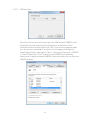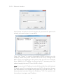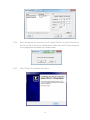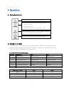
1
LR2000 POS Thermal Printer USER MANUAL Table of Contents 1 Introduction ..........................................................................................2 1.1 1.2 Safety Information ........................................................................................ 2 Electromagnetic compatibility statement ................................................. 3 2 Overview ................................................................................................4 2.1 2.2 Appearance ..................................................................................................... 4 Rear panel I/O connectors ............................................................................. 4 3 Installation ...........................................................................................5 3.1 3.2 3.3 3.4 3.5 3.6 Connecting Printer to Computer or POS Terminal ..................................... 5 Connecting to Cash Drawer........................................................................... 5 Connecting to Power ..................................................................................... 5 Load and Replace Paper Roll ......................................................................... 6 Ethernet IP Setup ........................................................................................... 8 Driver Installation .......................................................................................... 8 4 Operations........................................................................................... 14 4.1 4.2 4.3 4.4 4.5 Printer Control Panel .................................................................................... 14 Setting Printer Mode .................................................................................... 14 Self-Checking Function ................................................................................. 15 Preventive Maintenance .............................................................................. 15 Fixing Paper Jam ............................................................................................ 17 5 Connector Pinouts.............................................................................. 18 6 Troubleshooting ................................................................................ 20 7 Specifications .................................................................................... 22 1 1 Introduction Thank you for purchasing the LR2000 POS printer. Bematech is committed to continuously improve product quality and provide better after-sales service. In order to take full advantage of our devices, we strongly recommend that you take the time to read this manual before diving into software solution. Note: Information in this manual may change without prior notice. 1.1 Safety Information Before plug in the product, please make sure the power you provide meets the power requirements (such as voltage, frequency); Make sure the ground terminal of the power outlet is working properly. To avoid electric shocks, disconnect the power cord from the electrical outlet before relocating the system. Lightning may damage this product. During lightning storms, unplug the interface cable, power cable and any other connections. Turn off power before connecting any devices (except USB devices and Ethernet) to the printer. Do not attempt to open the chassis. You may be hurt by electric shock. For service, call your place of purchase. Do not spill liquid on the printer. Do not place any objects into the ventilation holes of this product. It may cause short-circuit of the internal components and cause a fire or electric shock. After the printer is stored below temperature of 10 ° C, please place it in room temperature (10-35 ° C) in the original packing for at least two hours to allow the printer to restore to room temperature before operation. This is to avoid condensation that might cause electrical damage. Keep the printer clean, dry, and away from dust, moisture and direct sunlight. Do not use harsh chemicals or strong cleaning solvents to clean the printer. Wipe it clean with a soft terry cloth applied with a mild solution Do not share the same power outlet with high-power electrical appliances; keep distance from high level magnetic interference. 2 The thermal head is a hot surface. Do not touch. When the following occurs: Liquid gets inside the POS printer; Accidental physical damage; The power cord or plug is damaged; POS printer produces a burning smell; Immediately disconnect the power supply, unplug the power cord, and contact a qualified service technician. 1.2 Electromagnetic compatibility statement FCC NOTICE This device complies with Part 15 of FCC Rules. Operations are subject to the following two conditions: (1) this device may not cause harmful interference, and (2) this device must accept any interference received, including interference that may cause undesired operation. EUROPEAN COMMUNITY (CE) MARK OF CONFORMITY This product is in conformity with the protection requirements of EU Council Directive 89/336/EEC on the approximation of the laws of the Member States relating to electromagnetic compatibility. Logic Controls cannot accept responsibility for any failure to satisfy the protection requirements resulting from a non-recommended modification of the product. This product has been tested and found to comply with the limits for Class A Information Technology Equipment according to CISPR 22 / European Standard EN 55022. The limits for Class A equipment were derived for commercial and industrial environments to provide reasonable protection against interference with licensed communication equipment. 3 2 Overview The LR2000 is a fast high quality POS printer using thermal technology for printing. It is compatible with most point-of-sale systems on the market. The printer can be used with computer peripheral systems, ECR and POS systems. The LR2000 was designed to facilitate simple and efficient operations. 2.1 Appearance 2.2 Rear panel I/O connectors At the rear panel of the LR2000 is a row of external I/O device connectors detailed as follows: USB RS232 ETHERNET CASH (LE2000E) DRAWER 4 DC IN 3 Installation 3.1 Connecting Printer to Computer or POS Terminal 3.1.1 Connect the interface cable (USB/serial) to the printer. Connect to LR2000 3.1.2 Connect the other end of interface cable (USB/serial) to the computer. Connect to Computer 3.1.3 For Ethernet interface, connect the Ethernet cable to Ethernet hub, switch, or router. 3.2 Connecting to Cash Drawer Connect cash drawer cable to cash drawer port at the back of printer Cash Drawer Port Use 12-24V/1A cash drawer only. Incompatible cash drawer will cause damage to both the cash drawer and the printer. Do not connect cash drawer port to the telephone line. It may cause failure condition on telephone line and printer. Cash drawer cable connection. 3.3 Connecting to Power 3.3.1 Make sure the AC power is unplugged and the printer is powered off before connecting the power cord. 5 3.3.2 Connect DC power cord to printer and then AC power plug to wall socket. AC adapter DC Power Cord 3.3.3 Turn on the power switch on the printer side. 3.4 Load and Replace Paper Roll 3.4.1 Press the Button to Open Paper Roll Cover 3.4.2 Remove the used paper roll to replace with a new roll Press the Cover Release Button 3.4.3 Load the paper roll as shown below: 6 Make sure the paper roll is loaded in the correct direction. Correct Direction 3.3.4 Wrong Direction Pull out the roll paper to the bottom front of the printer and then close the cover as shown below. Press down to close cover 3.3.5 Tear off extra paper roll with auto-cutter or with tear-cutter of the printer. Paper Roll Recommendation Paper Roll Specification Manufacturer HPK-110 Hansol patech Co.,Ltd AF50KS-E JUJO Paper Co.,Ltd TF-50KS-E Nippon Paper Industries Co.,Ltd PD-160R New Oji Paper Mfg,Co.,Ltd F380 Kansaki Specialty Papers,Inc. Improper paper roll may lead to critical fault on printer head and shortened the machine life span. Thus be sure to use the recommended paper roll. Any issue caused by using other branded paper roll will void the warranty, even during the warranty period. 7 3.5 Ethernet IP Setup The LR2000 comes with an easy IP setup utility for Windows. Run the LR2_IP_Setting.exe file in the software package and follow steps below. 3.5.1. Make sure the LR2000 is connected properly to the network. Then click on "Discovery" button to search for the connected printer. Then select the printer to be configured. 3.5.2. Edit the IP address value on the edit box above the "Discovery" button and click on "Update IP" button to write new IP address to printer. 3.6 Driver Installation 3.6.1 In the software package, run the BemaSetup_LR_v4.1.5.exe if you are using 32 bit Windows or BemaSetup_LR_x64_v4.1.5 if you are using 64 bit Windows and follow steps below to install the printer driver. 3.6.2 Then click “Next” on the Welcome screen. 8 3.6.3. Click “Continue” 3.6.4. Make sure the printer is turned ON. Next choose the printer interface according to the hardware connection. 9 3.6.5.1 USB Interface The driver will use a virtual printer port for USB (default USB001) and it should be selected automatically during driver installation. After installation has finished, please click “Yes” to print a test page to make sure the printer is working.If you don’t see test pages printing after installing the driver, please go to “Start -> Devices and printers -> LR2000 -> Printer Properties -> Port”, and select the USB001 port manually. Sometimes it might be named USB002 if there are other devices that use USB001 already). 10 3.6.5.2 Serial Interface Select the serial port from the drop down box if you know which port your printer connected to, or you can use “Detect” to automatically detect the port for you. Choose or Enter the Baud rate of the printer(Note: you can check the baud rate from the printer’s testing page, shutdown the printer and hold feed button while you turn the printer On), with flow control set to “None”. After driver installation, you can also change the port at any time from the LR2000 properties port setting tab Please make sure you choose port name start with LR_COM as shown below: 11 3.6.5.3 Ethernet Interface Click “Setup” to find the IP of the printer (if you know the printer’s IP already, you can also type it in manually). Then, click “Search” to search all available LR2000 printers over the network, choose the printer from the list on the left by clicking on the MAC column corresponding to the printer that you want to install the driver. Modify the IP address to desired value if necessary and click update to apply the new IP. Then click OK to finish. Note: If your printer’s IP address is not valid (no within the valid network IP range), you will be reminded to assign a valid IP to the printer. Assign a new valid address, click Update button and then click OK to finish. As demonstrated in picture below, the IP address “1.2.3.4” is invalid; it will then ask you to assign a new IP address. 12 3.6.6. After setting up the interface, click "Install Printer" to install the driver. You can verify if the driver installation is done successful by printing out a test page when prompted as shown below. 3.6.7 Click “Finish” to complete the setup. 13 4 Operations 4.1 Printer Control Panel Power light - Turns on when connected to power. Error light - Turns on under the following conditions: 1. Printer overheats 2. Receipt Paper Low 3. Paper cover and/or cutter replacement error Low Receipt Paper Light - Turns on when the receipt paper roll is low and/or wrong placement. Feed key - Press feed key to feed a length of paper. 4.2 Setting Printer Mode LR2000 printer is initially setup with default value. However, the default printer mode can be reconfigured to satisfy customer's needs through the DIP switch, which is located at the bottom of the printer. Function of DIP switch settings: Switch Function ON OFF 1 Select cutter Disable cutter Enable cutter 2 Select buzzer Enable buzzer Disable buzzer 3 Printing density High density Regular density 4 2-byte character mode Disable 2-byte characters Enable 2-byte Characters 5 Characters per line 42 42 6 Cash drawer output Enable Disable Baud rate for serial interface(refer to table below) 7-8 Baud rate(bps) 38400 115200 9600 19200 SW-7 ON OFF ON OFF 14 SW-8 ON ON OFF OFF 4.3 Self-Checking Function The Self-Checking Function allows the user to identify if the printer is operating normally. If the printer is detected with failure condition, please contact the distributor. (1) Self-checking Procedure: Make sure the printer is powered off. Press FEED button and switch on the power supply while the FEED button still pressed. The Self-Checking list should be printed when the printer is brought to power. (2) Self-Checking function printers out part of character set, command mode, interface type, printer settings, dip switch settings, etc. sequentially. (3) The auto-cutter cuts the receipt paper immediately when printing is finished. (4) The printer automatically goes into data receipt mode after finishing the self-check printing process. 4.4 Preventive Maintenance This printer has been developed to have a long life expectancy with no replacement of components and minimum user interference. But printer lifetime is highly influenced by the following factors: paper quality, regular preventive maintenance, environmental conditions and how carefully the user handles this product. (1) During normal operation some ink particles from the thermal paper will adhere to the thermal print head surface. Therefore, it is recommended to clean the printer head after 10 km of printed length or if printing quality is degrading. Switch off the printer before cleaning it. Clean the print head with a cotton swab, soaked with alcohol solvent (ethanol or isopropanol). Do not clean the print head with hard, abrasive objects or your fingers, since this can cause damage to its delicate surface. Clean the platen roller (rubber roller) with the cotton swab to remove any dust particles. CAUTION! The print head can be hot just after printing. Do not touch the print head; let it cool down before touching and cleaning. Because the thermal elements of the print head and driver IC are fragile, avoid touching them with any metal objects or any abrasive material. (2) During normal operation paper particles will build up inside the printer. This is normal, but dust and paper particles can prevent the sensors from functioning properly. To avoid that, verify once a year that the sensor surfaces 15 are unobstructed. To remove small paper particles from the sensors, use a small brush to wipe off the dust and paper particles. Do not attempt to use liquids to clean the sensors, in order to avoid damage. (3)The cutter is manufactured with hardened steel for maximum wear resistance. It is normal to have some dust buildup in the blades and this will not affect cutter performance. (4) Clean the external cabinet with a soft cloth, moistened in water or neutral detergent. Never use a tow chemically treated or chemical substances like alcohol or similar solvent. The use of these products can make the cabinet of the printer changes its color or be deformed. 16 4.5 Fixing Paper Jam The error light turns on and flashes with warning prompt when paper jam happens. Following steps below to clear the paper jam. 17 5 Connector Pinouts USB Connector (type B) Pin No. Signal Name 1 VBUS 2 D- 3 D+ 4 GND Serial Connector (DB9F) Pin No. Signal Name 1 DCD 2 TxD 3 RxD 4 DTR 5 GND 6 DSR 7 CTS 8 RTS 9 RI 18 Ethernet Connector (RJ45) Pin No. Signal Name 1 TX+ 2 TX- 3 RX+ 4 NC 5 NC 6 RX- 7 NC 8 NC Cash Drawer (RJ11) Pin No. Signal Name 1 Frame GND 2 Drawer kick-out drive 3 Drawer open/close signal 4 +24V 5 NC 6 Signal GND 19 6 Troubleshooting The following table describes some of the problems that may occur while using the printer. For every problem there is a possible cause and a suggested procedure to solve the problem. Problem Possible Cause There is no power in the electric outlet. The printer does not turn on. Check if there is a central switch for the room / outlets. Connect any other equipment to the outlet to check its operation. Possible problem with the power cord – it may be broken or not well connected to the printer and / or outlet. The communication cable has one or more lines with faulty The printer does not respond to Procedure connections / broken wires. the commands. Wrong programming sequences. The communication cable has one or more lines with faulty connections / broken wires. The interface pin-out does not follow the correct protocol. Communication is faulty. Turn off the printer; check the power cord continuity and a perfect connection between the printer and the electric outlet. Check for a good connection between the printer and the host or change the communication cable. Check the command set being used. The printer is configured to ESC/POSTM. Check for a good connection between the printer and the host or change the communication cable. Check if the adopted pin-out complies with the protocol being used for data transmission. Cables and Dip switches. If the baud rate set in the printer is different from the host’s baud rate, the printer will print random The baud rate is incorrectly set. characters or not print at all. Check carefully the host’s serial baud rate configuration as well as the printer’s dip switches settings. The error LEDs are on The printer informs you its status Check the Error and Paper LED status. A red light means there is an error in printer or paper loading. Paper dust and paper residues on Poor printing. the print head can influence printing quality 20 Clean the print head as described at chapter 3. Problem Possible Cause Procedure CAUTION! Do not touch the print head; let it cool down before touching, as it can be very hot after printing. The paper does not get out the printer. Switch off the printer and open the cover. Paper jam Remove the crumpled paper from the printer and install a new paper roll. If necessary, remove the rest of the disrupted paper. If the blade is blocked, switch off the printer. Open the cover. Remove the objects that are blocking the blade, such as paper clips. Blocked cutter blade. Objects may be blocking the blade Then turn the printer on again. Wait for the blade to return. The firmware will move the blade to the normal position without any intervention from the user. Close the cover and wait over 3 seconds. If this doesn’t solve the problem, please don’t try to fix it yourself. Call for assistance to fix the problem. Check if your printer device is online: Go to Star- Devices Printer is on but does not print You printer device type may be online and Printers- LR2000, if the printer is dimmed, then it’s offline. You can switch it to online by double click the printer icon and choose “Printer-check use Printer offline” option. 21 7 Specifications Characteristics Printing Property Communication Power Adaptor Environment Life Span Physical Characteristics Specification Printing Method Thermal Line printing Resolution 180x180dpi (7 dots/mm) Paper Width 79.5±0.5mm Printing Width 72mm Character Font ASCII Font A:12X24 ASCII Font A:9X24 Printer Density 512dot/line Printing Speed 250mm/s NV bitmap Flash 64kb Receipt Buffer 8kb Interfaces LR2000 - USB and Serial LR2000E - USB, Serial and Ethernet Input Voltage AC 100~240V, 50/60Hz Output Voltage DC 24V,2.5A Operating Temperature 0~45°C Storage Temperature -10~50°C Operating Humidity 10-80% Storage Humidity 10-90% Printer Head service lifetime 15,000,000 lines (100km) Auto-cutter 1,000,000cuts MCBF 60,000,000 lines Dimensions (W x D x H) 5.75" x 7.75" x 5.88" (146mm x 197mm x 149mm) Weight 3.4lb (1.54kg) Note: Printer speed changes as the as the combination of the data transmission speed and control command varies. 22 LR2000 POS Thermal Printer 23