1
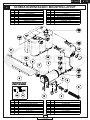
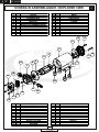
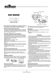
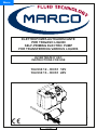
Menu
ELETTROPOMPA AUTOADESCANTE
PER TRAVASO LIQUIDI
SELF-PRIMING ELECTRIC PUMP
FOR TRANSFERRING VARIOUS LIQUIDS
AVVERTENZE D’USO
INSTRUCTIONS FOR USE
12/11/10 Ed.00
164 930 12 - OCK1 12V
164 930 13 - OCK1 24V
© 2010
S.p.A.
E N G
PRODUCT DESCRIPTION
A
Self-priming electric pump designed for lubricants and viscous fluids (see chapter
exclusions) for discontinuous or intermittent usage. .
The pumping elements are made up of bronze gear drives which can possibly even run
dry for brief periods. Completely equipped with fast connector for oil suction pipe.
TECHNICAL DETAILS
CODE
TYPE
VOLT
FUSE
164 930 12
164 930 13
OCK1
OCK1
12
24
7,5 A
4A
B
FLOW RATE
WEIGHT P.CS x CART.
ø 6 mm ø 8 mm ø 13 mm
20 l/h 60 l/h 330 l/h
1,4 kg
6
20 l/h 60 l/h 330 l/h
1,4 kg
6
AMBIENT CONDITIONS
TEMPERATURE: min. -10 °C / max. +60 °C
C
RELATIVE HUMIDITY: max. 90 %
WARNING: the above indicated temperature ranges are applicable to all components
of the pump and these limits must respected in order to avoid any possibile damage or
malfunctioning.
OPERATING CYCLE
D
The pump has been designed for discontinuous use. Under conditions of high operating
pressures (eg. with closed or blocked outlet, excessive length of the delivery circuit and/or
excessive pressure due to accessories), the pump can be subjected to elevated stresses
and overheating and therefore should not be used for prolonged periods under such
conditions.
APPLICATIONS
E
There are numerous fields of applications for the pump, however only exclusively with the
allowed liquids mentioned:
- transfer of lubricating oil
- transfer of viscous liquids
- transfer of oils, antifreezing
- circulation of viscous liquids
- draining of engine sumps
7
© 2010
S.p.A.
E N G
F
FLUIDS ALLOWED / NOT ALLOWED
ALLOWED:
FRESH WATER, MOTOR OIL (max 85°C-185°F)
DIESEL FUEL with viscosity between 2 and 5.35 cSt (to 37,8°C - 100°F temperature)
Minimum flashpoint (PM): 55°C-131°F.
NOT ALLOWED:
RELATED DANGERS
- PETROL (GASOLINE)
- FIRE EXPLOSION
- FIRE EXPLOSION
- FLAMMABLE LIQUIDS with PM< 131°F
- LIQUIDS WITH VISCOSITY > 20 cSt
- MOTOR OVERHEATING
- FOODSTUFF LIQUID CONTAMINATION
- FOODSTUFF LIQUIDS
- PUMP CORROSION
- CORROSIVE CHEMICAL PRODUCTS
INJURY TO PERSONNEL
- SOLVENTS
- FIRE EXPLOSION
DAMAGE TO SEALS
WARRANTY EXPIRES IF MAX FLUID TEMPERATURE IS EXCEEDED
G
TRANSPORTATION AND HANDLING
Due to limited weight and dimensions the pump does not require the use of any special
handling or lifting equipment. When handling manually, normal personal protective gear
should be worn (safety shoes with toe piece, etc.)
The pump is carefully packed prior to shipment. Upon receiving, the pump packaging
should be inspected for damages and the pump stored in a dry area.
H
INSTALLATION
It is recommended that the use of the pump be according to normative safety standards
and also as per the precautions listed below.
H-1
PRELIMINARY CHECKS
Check that there has been no damage to the pump during transportation or storage. Both
inlet and outlet ports should be carefully cleaned removing possible dust or residual
packaging material. Verify that the available electrical power supply corresponds to the
pump specification requirements.
H-2
POSITIONING
The pump can be mounted in any position. Fix the pump utilizing suitable screws
corresponding to the antivibration mounts supplied with the pump.
8
© 2010
S.p.A.
E N G
WARNING: THE PUMP MOTOR IS NOT EXPLOSION PROOF
Do not install the pump where flammable vapours or gases may be present.
Install the pump in an accessible place for inspection.
It is good practice to avoid any pump contact with water splashes possibly causing
water seepage into the motor with high risk of internal oxidation and/or short circuit.
TUBING CONNECTIONS
H-3
- Prior to making any tube/hose connections, check that the inlet ports have no end caps;
- Do not position the pump at a higher greater than 1,5 m with respect to the minimum
level of the fluid to be transferred. Damage may occur if this height is exceeded as the
pump may not draw fluid. Make sure that the outlet tube is empty and without chokes;
- Avoid choking the inlet or outlet tubes so that efficiency is optimized. The use of an inlet
filter is mandatory especially with fluids containing impurities (ASTM mesh 35).
In this case frequent cleaning and maintenance of the filter is advisable. Utilize tubes
and connection pieces that are resistant to the fluid types handled and avoid any possible
environmental dispersion.
H-4
ELECTRICAL CONNECTION
The electrical installation of the pump must include a protection fuse which is suitably
rated as indicated on the motor label.
WARRANTY
EXPIRES
IF
NO
FUSE
IS
UTILIZED
Always mount the anti vibration rubber fittings supplied with the pump kit. Their usage
ensures a consistent reduction in noise and vibration levels.
Electrical cabling size should depend on the distance between pump and battery power
supply.
Up to 4 m length: 1,5 mmq
The use of undersized cabling can cause overheating of the electrical wiring and
subsequent fire hazard. There will also be a voltage drop at the motor terminals with a
consequent reduction in efficiency.
9
© 2010
S.p.A.
E N G
To ensure the correct directional flow of the fluid as indicated by the arrow on the top plate,
it is necessary to connect the positive pole ( + ) of the battery supply to the red wire on the
motor end-cap and the negative pole ( - ) to the black wire. Electrical connections must be
made using adequate terminal blocks and connectors ensuring a tight fitment of the
electrical cables. Bad wiring can cause power losses and/or over heating of the cabling
itself.
WARNING: it is the responsability of the installation technician to ensure a
correctly designed circuit installation fitted according to regulations.
Environmental risks must be taken into account with installation.
I
TROUBLESHOOTING
L-1
I-1
CHECK POINTS IF THE PUMP HAS STOPPED OR WILL NOT START
- Check the effectiveness of the battery power supply (voltage activity)
- Check if the fuse has blown
- Check for any foreign matter present in-between the pump gear drives. To do this,
disconnect the power supply and unscrew the four fixing screws, remove the pump front
cover plate and inspect the pump chamber. Replace the cover plate in the same initial
position after inspection.
- Avoid running the pump dry for more than a few minutes. Pumps found defective that
have run dry in the absence of fluid are not covered by warranty.
- The average life span of the motor commutator brushes is approximately 2000
hours under normal operating conditions. Stoppages are possible due to brush wear
and tear after such a time period.
I-2
WHY THE PUMP WILL NOT PRIME ITSELF?
- The pump is fitted at a height greater than 1,5 m above the fluid level.
- The pump has run dry for too long a period
- Long periods of inactivity. In this case it is advisable to add liquid directly into the pump
chamber before start-up. It is also advisable to add, before running the pump, a drop of
lubricating oil inside the pump only.
- Air leak at the suction pipe due to the following reasons:
- Possible cuts in the pipe, inadequate hose clamps, malfunctioning of the filter due to
defective/worn seals or filter clogged.
- Air leak at the pump front plate cover due to the following reasons:
- Loose fixing screws, poor effectiveness of the seal.
- Faulty electrical cable connections
- Presence of obstructions or restrictions in the suction or delivery pipes
- Presence of liquid loops in the outlet tube.
I-3
GOOD PRACTICES ENSURING A WELL FUNCTIONING PUMP
No particular maintenance is required if the pump is utilized for the transfer of diesel fluids
or oils.
10
© 2010
S.p.A.
E N G
NORMAL MAINTENANCE
I-4
Check every month the pump chamber and keep clean from any foreign matter.
Check every month that electrical wiring is in good condition.
Every 2000 hours of pump operation substitute the motor brushes.
INDICATORS THAT THE PUMP IS FUNCTIONING CORRECTLY
I-5
- Temperature of pump body and motor frame is within 60°C - 70°C (140°F-158°F)
- Regular flow and constant pump noise levels
- Amp-draw within the limits indicated in the technical details.
TO OPEN THE PUMP
I-6
- It is recommended that a specialized service technician be consulted for any pump
repair work or the replacement of worn out internal components, exclusively with original
spare parts.
- During the warranty period, only by authorized Marco S.p.A. personnel, failing which the
warranty will expire.
ENVIRONMENTAL DISPOSAL
L
Do not dispose of pumps into household waste: pumps that are no longer usable, must
be collected separately and and disposed of in an enviromentally correct manner.
PACKAGING ENVIRONMENTAL DISPOSAL
L-1
The user is invited to effect a proper waste separation, in order to facilitate the recycling of
the materials of which the packing is composed; disposal like CER 15.01.01/02
WARRANTY
M
1) The Warranty period is 2 years from date of purchase on production of the
appropriate sales invoice.
2) Should the original sales invoice not be available, then the 2 year warranty period
will be valid from date of production.
3) The Warranty becomes null and void in the case of incorrect utilization or disregard
of the instructions contained herein.
4) The Warranty only covers original production defects.
5) The Warranty does not cover any related installation costs involved.
6) Transport costs are refundable only in the case where warranty has been duly
recognized and accepted by Marco Spa. These costs will be limited to the actual
shipment costs between Marco Spa warehouse and the client's delivery address.
7) No credit notes or replacement items will be issued prior to the receipt and proper
testing of any Marco goods that are deemed faulty.
11
© 2010
S.p.A.
I T
E N G
SEQUENZA DI MONTAGGIO / MOUNTING SEQUENCE
Per dati tecnici e prestazioni della pompa, consultare il relativo manuale allegato.
1.
2.
3.
4.
5.
6A.
6B.
7.
8.
9.
10.
11.
12.
Montare gli antivibranti (2) sulla pompa (1);
Avvitare il portagomma (4), completo di o-ring (3), sul corpo pompa (1);
Infilare la fascetta stringi tubo (5) sul tubo retinato (6);
Calzare il tubo retinato (6) sul portagomma (4) ed avvitare la fascetta stringitubo (5);
Avvitare l’innesto rapido (7) sul corpo pompa (1);
Nel caso si voglia utilizzare il tubo Rilsan Ø 8/6 L=1.2 m (8) come aspirazione, infilarlo
nell’innesto rapido (7) fino a sentire uno scatto: per accertarsi della corretta installazione
verificare che tirandolo non si sfili dall’innesto rapido (7);
Nel caso si voglia utilizzare il tubo Rilsan Ø 6/4 L=1.2 m (11) come aspirazione, infilare il
tubo Rilsan 8/6 L=0,3 m (9) nell’innesto rapido (7) fino a sentire uno scatto.
Per accertarsi della corretta installazione verificare che tirandolo non si sfili.
Ripetere la stessa operazione infilando l’altra estremità del tubo Rilsan (9) nel giunto (10).
Con le stesse modalità infilare il tubo Rilsan (11) nel giunto (10) e verificarne il corretto montaggio;
Per estrarre i tubi Rilsan (8) (9) (11) dall’innesto rapido (7) o dal giunto (10), premere la ghiera
in plastica nera contro la parte in metallo, nella direzione opposta a quella di estrazione del tubo;
Connettere il cavo rosso della pompa (13A) al cavo rosso (13B) delle pinze fornite;
Connettere il cavo nero della pompa (14A) al cavo nero (14B) delle pinze fornite;
Per avviare la pompa (1) in modalità aspirazione dal tubo Rilsan (8), (11) verso il tubo retinato (6),
come indicato dalla freccia applicata sul corpo pompa (1), connettere la pinza rossa (13C)
al polo positivo (+)(13D) della batteria (12) e la pinza nera (14C) al polo negativo (-)(14D);
Per arrestare la pompa (1), staccare una delle pinze (13C), (14C), dai poli positivo (13D),
o negativo (14D);
Per invertire la direzione del flusso ed aspirare dal tubo retinato (6) verso il tubo Rilsan (8), (11)
invertire la posizione delle pinze (13C), (14C) sui poli (13D), (14D).
For technical data of the pump see the attached instruction manual
1.
2.
3.
4.
5.
6A.
6B.
7.
8.
9.
10.
11.
12.
Mount the isolators (2) on the pump (1);
Screw the hose fitting (4) complete with OR (3), on the pump (1);
Fit the hose clamp (5) on the hose (6);
Connect the hose (6) on the hose fitting (4) and screw the hose clamp (5);
Screw the quick fitting (7) on the pump body (1);
As an option, the Rilsan hose Ø 8/6 L=1.2 m (8) can be connected on the inlet side: for its proper
connection, press the hose in the quick fit (7) and check by pulling for sufficient force;
As an option, the hose Ø 8/6 L=0.3 m (9) can be connected on the inlet side: the quick
coupling (10) must be used to join the Rilsan hose (9) with Rilsan hose Ø 6/4 L=1.2 m (11).
Check by pulling for sufficient retention force;
To pull out the Rilsan hose (8), (9), (11) from quick fit (7) or coupling (10), press the black chape
and pull the hose all at once;
Connect the red wire (13A) on the pump to the red wire (13B) of the tongs;
Connect the black wire (14A) on the pump to the black wire (14B) of the tongs;
To start the pump (1) connect the red tong (13C) to the positive pole (+)(13D) of the battery (12)
and the black tong (14C) to the negative pole (-) (14D). The pump will transfer fluids in the
direction of the arrow on the pump body;
To stop the pump (1) disconnect the red (13C) or black (14C) tong from either pole (13D),(14D);
To revert the flow direction, connect the red tong (13C) to the negative pole (-)(14D)
and the black tong (14C) to the positive pole (+)(13D).
12
© 2010
S.p.A.
E N G
SCHEDA DI MONTAGGIO / MOUNTING LAYOUT
N
Pos. Q.tà
1
2
3
4
5
6
7
8
Pos. Q.tà
Descrizione
POMPA
ANTIVIBRANTI
O-RING
PORTAGOMMA
FASCETTA
TUBO RETINATO
INNESTO RAPIDO
TUBO RILSAN Ø 8/6 L=1,2 m
1
4
1
1
1
1
1
1
9
10
11
12
13
14
15
1
1
1
1
1
1
1
Descrizione
TUBO RILSAN Ø 8/6 L=0,3 m
GIUNTO
TUBO RILSAN Ø 6/4 L=1,2 m
BATTERIA (NON FORNITA)
PINZA ROSSA
PINZA NERA
FUSIBILE 7,5 A
13D
+
14D
-
13C
+
15
11
10
9
12
14C
1
14B
-
-
7
14A
-
13B
+
13A
8
3
+
5
SGANCIO TUBO RILSAN
RILSAN TUBE RELEASE
6
10
Pos. Q.ty
1
2
3
4
5
6
7
8
1
4
1
1
1
1
1
1
8
4
2
Pos. Q.ty
Description
PUMP
ANTIVIBRATION MOUNT
O-RING
TUBE OUTLET
HOSE CLAMP
TUBE
QUICK FIT
RILSAN TUBE Ø 8/6 L=1,2 m
9
10
11
12
13
14
15
1
1
1
1
1
1
1
13
© 2010
S.p.A.
Description
RILSAN TUBE Ø 8/6 L=0,3 m
COUPLING
RILSAN TUBE Ø 6/4 L=1,2 m
BATTERY (NOT INCLUDED)
RED CROCODILE CLIP
BLACK CROCODILE CLIP
7,5 A FUSE
I T
I T
E N G
SCHEDA DI ASSEMBLAGGIO / EXPLODED VIEW
Pos. Q.tà
1
2
3
4
5
6
7
8
9
10
11
12
1
1
1
2
1
1
1
1
1
1
2
2
Pos. Q.tà
Descrizione
13
14
15
16
17
18
19
20
21
22
23
CORPO
MIM
GUARNIZIONE
TIRANTE
INDOTTO
CUSCINETTO
MOLLA DI COMPENSAZIONE
CARCASSA
O-RING
CALOTTA PORTASPAZZOLE
O-RING
RONDELLA
2
1
1
1
1
1
4
1
1
1
4
O
Descrizione
DADO
INGRANAGGIO FOLLE
LINGUETTA
INGRANAGGIO TRAINANTE
O-RING
PIATTELLO
VITE
RACCORDO
O-RING
RACCORDO
ANTIVIBRANTE
10
12
9
8
13
4
11
5
3
22
7
2
6
1
14
18
23
21
15
20
16
17
19
Art. Q.ty
1
2
3
4
5
6
7
8
9
10
11
12
1
1
1
2
1
1
1
1
1
1
2
2
Art. Q.ty
Description
13
14
15
16
17
18
19
20
21
22
23
PUMP BODY
RUBBER LIP SEAL
GASKET
ROD
ARMATURE
BALL BEARING
COMPENSATION SPRING
PUMP FRAME
O-RING
BRUSH HOLDER
O-RING
WASHER
2
1
1
1
1
1
4
1
1
1
4
14
© 2010
S.p.A.
Description
NUT
IDLE GEAR
KEY
DRIVING GEAR
O-RING
TOP PLATE
SCREW
TUBE OUTLET
O-RING
NIPPLE
ANTIVIBRATION MOUNT
E N G
I T
INGOMBRI / DIMENSIONS
P
14,5
108
99
60
38
5
18
80
136
102
17
10
60
50
10
88
64
29
119
15
© 2010
S.p.A.
I T
E N G
DIAGRAMMI / DIAGRAM
Q
l/min
DIAGRAMMA PORTATA
FLOW RATES DIAGRAM
8
7
6
5
4
3
2
1
0
Ø 13
Ø8
Ø6
25
30
35
40
45
50
°C
DIAGRAMMA ASSORBIMENTI
AMPERE-DRAW DIAGRAM
5
A
4
12V
3
2
24V
1
0
25
30
35
40
°C
16
© 2010
S.p.A.
45
50
Associato AIB
associazione
industriale
bresciana
DICHIARAZIONE DI CONFORMITA’ C.E.
E.C. DECLARATION OF CONFORMITY
Confermiamo che il prodotto:
We confirm that the product:
164 930 12 - OCK1 12V Kit cambio olio / Oil change kit
164 930 13 - OCK1 24V Kit cambio olio / Oil change kit
E’ conforme alla Direttiva 2004/108/CE (ex.89/336/CE) relativa alla Compatibilità Elettromagnetica.
Is in conformity with the Directive 2004/108/EC (ex.89/336/EC) relating to Electromagnetic Compatibility.
Questa dichiarazione è valida per tutti gli articoli prodotti secondo la documentazione tecnica che è parte di questa
dichiarazione. In caso di eventuali verifiche pertinenti alla Compatibilità Elettromagnetica sono state applicate le
seguenti normative:
This declaration is valid for all products which are produced in accordance with the technical documentation which is
a part of this declaration. For verification of conformity with regard to Electromagnetic Compatibility the following
standards are applied:
EN 55014-1
Compatibilità elettromagnetica.
Requisiti per gli elettrodomestici,
gli utensili elettrici ed apparecchi similari.
Parte 1: Emissione.
Electromagnetic compatibility.
Requirements for household appliances,
electric tools, and similar apparatus.
Part 1: Emission.
Questa dichiarazione è rilasciata sotto la responsabilità esclusiva di:
This declaration is given under the sole responsibility of:
MARCO S.P.A.
Via Mameli 10 - 25014 Castenedolo - Brescia - Italy
Tel. 030/2134.1 Fax 030/2134.300
17
© 2010
S.p.A.
NOTE / NOTES
18
© 2010
S.p.A.
Per ulteriori informazioni vedere nostro sito internet - www.marco.it
Marco S.p.A Via Mameli 10 - 25014 Castenedolo - Brescia - Italia
tel. +39 030 2134.1 / Fax +39 030 2134.300
For further information visit our web site - www.marco.it
Marco S.p.A Via Mameli 10 - 25014 Castenedolo - Brescia - Italy
tel. +39 030 2134.1 / Fax +39 030 2134.300