1
MAN609-S
Users Manual
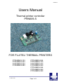
Thermal printer controller
PRN609-S
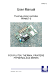
FOR FUJITSU THERMAL PRINTERS
FTP629MCL103
FTP629MCL363
FTP629MCL364
FTP629MCL383
FTP639MCL064
FTP639MCL103
FTP639MCL303
FTP639MCL363
FTP639MCL364
FTP639MCL383
FTP639MCL393
11 March 2005
Page 1 of 1
MAN609-S
Version history
Version
1.0
1.1
2.0
Date
030328
030902
Init
BB
BB
TLP
Status
Released
Released
Open
Description
First release
Minor error removed
New stencil
Copyright 1999-2003 by I/F-COM A/S.
All rights reserved.
I/F-COM A/S has prepared this manual for use by I/F-COM A/S’ customers.
The information contained herein is the property of I/F-COM A/S and shall not be
reproduced in whole or in part without the prior written approval of I/F-COM A/S.
I/F-COM A/S reserves the right to make changes without notice to the specifications
and materials contained herein and shall not be responsible for any damages
(including consequential) caused by reliance on the materials presented, including
but not limited to typographical, arithmetic or listing errors.
Windows is registered trademark of Microsoft Corporation.
Fujitsu is registered trademark of Fujitsu Corporation.
11 March 2005
Page 2 of 2
MAN609-S
Safety Precautions
•
•
•
•
Please read and understand these specifications thoroughly before using the
printer. Please keep the specifications carefully in a place where they may be
easily consulted when the printer is used.
Please do not modify or service this printer as this may cause unpredictable
faults to occur.
The product is not intended to be installed in devices such as those used in lifesupport medical equipment, undersea relays, and aerospace applications or for
nuclear power control, in which extremely high reliability is required. If you are
considering such applications, please consult our customer service department.
There is a general possibility of component failure. Every effort has been made to
improve product quality but such failures cannot be completely excluded. Please
assume that such failure may occur before using this printer.
We would urge that these specifications should be thoroughly understood and the
printer used safely in your company or associated organization. Please indicate or
describe in your products and in the user manuals those items, which are related to
the prevention or avoidance of danger and draw these to the attention of the
eventual client (the user).
This manual may only be used as appendix to the product and may only be used, as
a help to better understand the functionality of the product. Any approval of the
product may only be done based upon sample of the product. Approval based upon
the specification is not accepted by I/F-COM.
11 March 2005
Page 3 of 3
MAN609-S
Table of contents
1
SYSTEM DESCRIPTION.................................................................................... 6
2
INSTALLATION ................................................................................................. 6
2.1
Unpacking ................................................................................................................................ 6
2.2
Labels ....................................................................................................................................... 6
2.3
Installation................................................................................................................................ 7
2.4
Power supply ........................................................................................................................... 7
3
SPECIFICATIONS.............................................................................................. 8
4
FUNCTION ......................................................................................................... 9
4.1
Serial communication ............................................................................................................. 9
4.2
USB communication ............................................................................................................... 9
4.3
IRDA communication .............................................................................................................. 9
4.4
Auto detect printer .................................................................................................................. 9
4.5
Auto form feed ......................................................................................................................... 9
4.6
Firmware upgrade ................................................................................................................. 10
4.7
Character design ................................................................................................................... 11
4.7.1 Normal character................................................................................................................. 11
4.7.2 Low character...................................................................................................................... 11
4.7.3 Underline ............................................................................................................................. 12
4.7.4 Reverse ............................................................................................................................... 12
4.7.5 Font size.............................................................................................................................. 12
4.8
Control and Escape sequences ........................................................................................... 13
4.8.1 Escape sequences, overview.............................................................................................. 13
4.8.2 Small font ............................................................................................................................ 14
4.8.3 Low font............................................................................................................................... 14
4.8.4 Narrow font.......................................................................................................................... 14
4.8.5 Normal font.......................................................................................................................... 14
4.8.6 Wide font ............................................................................................................................. 14
4.8.7 High font .............................................................................................................................. 15
4.8.8 Large font ............................................................................................................................ 15
4.8.9 X-large font.......................................................................................................................... 15
4.8.10
Line feed ......................................................................................................................... 15
4.8.11
Feed forward................................................................................................................... 15
4.8.12
Reverse off...................................................................................................................... 16
4.8.13
Reverse on...................................................................................................................... 16
4.8.14
Underline off.................................................................................................................... 16
4.8.15
Underline on.................................................................................................................... 16
11 March 2005
Page 4 of 4
MAN609-S
4.8.16
4.8.17
4.8.18
4.8.19
4.8.20
4.8.21
4.8.22
4.8.23
4.8.24
4.8.25
4.8.26
4.8.27
4.8.28
4.8.29
4.8.30
4.8.31
4.8.32
4.8.33
4.8.34
5
Initialize printer................................................................................................................ 16
Request software version and dot size........................................................................... 17
Request status ................................................................................................................ 17
Request analog voltage .................................................................................................. 17
Request temperature ...................................................................................................... 18
Feed paper...................................................................................................................... 18
Compensate burn time.................................................................................................... 18
Graphic line..................................................................................................................... 18
Set printer size ................................................................................................................ 19
Change auto feed settings .............................................................................................. 19
Max speed ......................................................................................................................19
Auto request.................................................................................................................... 20
Black mark ...................................................................................................................... 21
Feed to next black mark.................................................................................................. 22
Delimiter .......................................................................................................................... 22
Bar code width setting..................................................................................................... 22
Bar code height setting ................................................................................................... 22
Bar code printing............................................................................................................. 23
Code128 barcode table................................................................................................... 24
MAINTENANCE ............................................................................................... 25
5.1
Normal operation ................................................................................................................... 25
5.2
Store/Transport...................................................................................................................... 25
6
SPECIFICATIONS............................................................................................ 26
6.1
Electrical data ........................................................................................................................ 26
6.2
Mechanical data ..................................................................................................................... 26
6.3
Environmental data ............................................................................................................... 26
6.4
EMC & ESC............................................................................................................................. 26
6.5
Connector pin assignment ................................................................................................... 27
6.5.1 Motor/Sensor connector CN1.............................................................................................. 27
6.5.2 Thermal head connector CN2 ............................................................................................. 27
6.5.3 Reserved connector CN3.................................................................................................... 28
6.5.4 Aux input CN4 ..................................................................................................................... 28
6.5.5 Cutter connector CN5.......................................................................................................... 28
6.5.6 USB connector CN6 ............................................................................................................ 29
6.5.7 Power connector CN7 ......................................................................................................... 29
6.5.8 AUX connector CN8 ............................................................................................................ 29
6.5.9 Serial connector CN9 .......................................................................................................... 30
6.6
7
Mechanical drawings ............................................................................................................31
APPENDIX ....................................................................................................... 32
11 March 2005
Page 5 of 5
MAN609-S
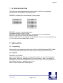
1 SYSTEM DESCRIPTION
This reference manual describes the specifications, function, and operating
procedures for the PRN609-S interface boards.
PRN609-S is designed for the following Fujitsu printers:
FTP629MCL103
FTP629MCL363
FTP629MCL364
FTP629MCL383
FTP639MCL064
FTP639MCL103
FTP639MCL303
FTP639MCL363
FTP639MCL364
FTP639MCL383
FTP639MCL393
PRN609-S consists of an interface board.
The communication is RS232, USB
PRN609-S can print graphic data either compressed or non-compressed.
Burn time can be set to control the printing intensity
Windows 2000 and XP are available at http://www.if-com.com, for easy operation by
pc. Linux drivers are available upon request.
2 INSTALLATION
2.1 Unpacking
Remove the cover observing precautions for Electro Static Discharge (ESD). Make
sure that board is handled with care with respect to Electrostatic environment.
2.2 Labels
PRN609-S has 3 labels;
Label 1 on backside ex. Ifxxxxxx is a unique ID number. For service and question
based upon 1 particular board please refer to this number. Label 2 on topside ex.
PRN609-S is part number. Please refer to this number upon reordering. Make sure
that software revision is applied at same time.
Label 3 is an internal code. Please ignore
11 March 2005
Page 6 of 6
MAN609-S
2.3 Installation
PRN609-S is fastened in the product by 4 M3 screws. The cables (for the thermal
head, the stepper-motor and detector) are placed in the thermal printer connector on
the PCB. Mounting holes are grounded connected to electrical ground.
(a)
To connect or remove the connector, always turn off the power in advance. If
the connector is connected or removed while the power to the printer is on,
errors may occur.
(b)
The connector of each cable must be correctly locked and connected. The
connector at the head side has no lock feature. Check that the connector at the
head side is completely inserted.
(c)
To install the interface, carefully check each cable so that excessive force is
not applied to each cable. Especially, carefully check the head connection
cable because it affects the head pressure force. If the print head connector is
not completely connected, overheating or burning may occur in the print head.
(d)
Be sure to add grounding cable from printer body to interface ground. Make
sure that ground is present at any mechanical settings, like head up and paper
out.
2.4 Power supply
Single power supplies for the PRN609-S controller board. The nominal supply
voltage is 24VDC, with ±10 % in tolerance. Make sure that voltages never
exceed 26,5 VDC.
(a)
The power supply unit that satisfies the specified specifications must be used.
If a power supply unit that does not satisfy the specified specifications is used,
normal operation is not assured and errors may occur.
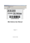
(b) To turn on or off the power, a protective circuit must be mounted on the control
board in advance. For safety, the following voltage change conditions must be
satisfied.
10 ms maximum
10 ms maximum
24 V power line
6 V maximum
6 V maximum
At power on
At power off
11 March 2005
Page 7 of 7
MAN609-S
3 SPECIFICATIONS
Interface
Serial RS232, USB1.1
Data format
Max 460.800 baud, 8 data bit, none parity, 1 stop bit, (115.200 baud, default)
Handshake
Hardware
Command set
I/F-com
Transmission to host Requested status etc.
Printer supply
24VDC ± 10% tolerance.
Power on self test
Feed
Voltage compensation Burn time
Current consumption Operating 130mA, Printing up to 10A @ 24V (TBD)
Printing speed
Up to 200mm/sec
Font set
Western (Code 850, char 32-159)
Character size
8x16, 16x16, 8x32, 16x32, 16x64, 32x32, 32x64, 64x128
Character type
Normal, Underline, Reverse (white on black)
Default font
16x32
Paper detect
Digital
Graphics
Normal / Compressed
Auto load
50mm
Form feed
50mm
Line feed
LF
Maximum dimensions Width 77mm, Depth 50mm, Connected height 15mm
Mounting holes
Width 71mm, Depth 44mm, Diameter 3.3mm
Connectors
CN1, Connector type: 3800-10P-T-S
CN2, Connector type: 3800-30P-T-S
CN3, Connector type: 53047-0410
CN4, Connector type: 53324-0710
CN5, Connector type: JS-1132-4
CN6, Connector type: UBBR-04SW11
CN7, Connector type: 43045-0400
CN8, Connector type: 53324-0510
Weight
25g
Storage -40ºC to +85ºC 0-90 Operating 0C to +70ºC 10-90%RH
Temperature
Shock
100G XYZ
EMC
Emission: E-Field EN50081-1-1, Conducted EN50081-1-2
Immunity: E-field EN50082-1-1, Conducted EN50082-1-2, Over voltage EN50082-1-3
Drivers
Windows2000 and Windows XP + embedded, Linux,
Approvals
CE, UL
Accessories
Serial Interface cable: CBL-002, 9pol Sub-D, female
Power cable: CBL-025
11 March 2005
Page 8 of 8
MAN609-S
4 FUNCTION
4.1 Serial communication
It is possible to receive and send data (8 bit) via the serial port. The default baud
rate is 115.200, and there are no parity bit and one stop bit.
Handshake signals are hardware. Other baud rates are available upon request.
4.2 USB communication
The USB port is fully compatible with USB 1.1 .The PRN609-S interface board is
100% compatible with the printer class specification.
I/F-COM A/S Vendor number: 5098
4.3 IRDA communication
IRDA Communication is available upon request.
4.4 Auto detect printer
At power up the PRN609-S, detects the printer size.
4.5 Auto form feed
When paper is out, it is possible to form feed new paper automatic. While the
thermal head is down, place the paper at the roller.
After 2 seconds the paper will be pulled in automatically.
Form feed length is factory set
11 March 2005
Page 9 of 9
MAN609-S
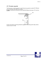
4.6 Firmware upgrade
The firmware can be upgraded. In case firmware up grade is needed I/F-COM will
provide windows utility and the firmware.
In order to upload new firmware to the PRN609-S Board, the jumper JP1 must be
shorten.
JP1
Further instruction concerning firmware upgrade comes along with utility and the
firmware from I/F-COM.
11 March 2005
Page 10 of 10
MAN609-S
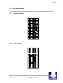
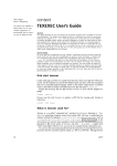
4.7 Character design
The following figures describe the design of different types of characters (small):
4.7.1
Normal character
4.7.2
Low character
11 March 2005
Page 11 of 11
MAN609-S
4.7.3
Underline
When underline characters are printed the last line in the character matrix will be
marked.
4.7.4
Reverse
When reverse characters are printed the character matrix will be negated.
4.7.5
Font size
Font
Small
Low
Narrow
Normal
Wide
High
Large
X-large
Width
Half
Normal
Half
Normal
Double
Normal
Double
Quadruple
Height
Half
Half
Normal
Normal
Normal
Double
Double
Quadruple
A build-in smooth function is implemented to obtain best character quality.
11 March 2005
Page 12 of 12
MAN609-S
4.8 Control and Escape sequences
The control of the PRN609-S printer interface is performed by a command set of
escape sequences. The following commands are used. All other commands are
ignored.
4.8.1
Escape sequences, overview.
ESCAPE SEQUENCES,
ASCII
NUL
SOH
STX
ETX
EOT
ENQ
ACK
BEL
LF
FF
SO
SI
DLE
DC1
SYN
ETB
CAN
EM
SUB
GS+n
RS+n
US+d1..dLast
ESC+205+1+C+n
ESC+205+2+d+m+n
ESC+n+m
ESC+205+1+j+n
ESC+205+3+97+m+n+o
ESC+205+0+c
ESC+205+1+i+n
ESC+e+m
ESC+h+n
ESC+k+m n+d1 to dn
FUNCTION
Small font
Low font
Narrow font
Normal font
Wide font
High font
Large font
X-large font
Line feed
Forward feed
Reverse off
Reverse on
Underline off
Underline on
Initialize printer
Request software version
Request status
Request analogue voltage
Request temperature
Feed paper
Burn compensate
Print graphic line
Set printer size
Change auto feed settings
Set max speed
Auto request
Black mark parameters
Feed to next black mark.
Delimiter
Bar code width setting
Bar code height setting
Bar code printing
11 March 2005
Page 13 of 13
MAN609-S
4.8.2
Small font
[Name]
[Format]
[Description]
4.8.3
Low font
[Name]
[Format]
[Description]
4.8.4
[Description]
Narrow font (8x32)
ASCII
STX
Hex
02
Decimal
2
Select normal font from the current print position. This is the default
font after power up or reset.
Normal font
[Name]
[Format]
[Description]
4.8.6
Low font (16x16)
ASCII
SOH
Hex
01
Decimal
1
Select low font from the current print position.
Narrow font
[Name]
[Format]
4.8.5
Small font (8x16)
ASCII
NUL
Hex
00
Decimal
0
Select small font from the current print position.
Normal font (16x32)
ASCII
ETX
Hex
03
Decimal
3
Select normal font from the current print position. This is the default
font after power up or reset.
Wide font
[Name]
[Format]
[Description]
Wide font (32x32)
ASCII
EOT
Hex
04
Decimal
4
Select wide font from the current print position.
11 March 2005
Page 14 of 14
MAN609-S
4.8.7
High font
[Name]
[Format]
[Description]
4.8.8
Large font
[Name]
[Format]
[Description]
4.8.9
High font (16x64)
ASCII
ENQ
Hex
05
Decimal
5
Select high font from the current print position.
Large font (32x64)
ASCII
ACK
Hex
06
Decimal
6
Select large font from the current print position.
X-large font
[Name]
[Format]
[Description]
X-large font (64x128)
ASCII
BEL
Hex
07
Decimal
7
Select X-large font from the current print position.
4.8.10 Line feed
[Name]
[Format]
[Description]
Line feed
ASCII
LF
Hex
0A
Decimal
10
The text data in the buffer will be printed
4.8.11 Feed forward
[Name]
[Format]
[Description]
Feed forward
ASCII
FF
Hex
0C
Decimal
12
The printer will print content of the buffer and feed forward 50mm
11 March 2005
Page 15 of 15
MAN609-S
4.8.12 Reverse off
[Name]
[Format]
[Description]
Reverse off
ASCII
SO
Hex
0E
Decimal
14
This command will switch off reverse printing
4.8.13 Reverse on
[Name]
[Format]
[Description]
Reverse on
ASCII
SI
Hex
0F
Decimal
15
This command will switch on reverse printing
4.8.14 Underline off
[Name]
[Format]
[Description]
Underline off
ASCII
DLE
Hex
10
Decimal
16
This command will switch off underline printing
4.8.15 Underline on
[Name]
[Format]
[Description]
Underline on
ASCII
DC1
Hex
11
Decimal
17
This command will switch on underline printing
4.8.16 Initialize printer
[Name]
[Format]
[Description]
Initialize
ASCII
SYN
Hex
16
Decimal
22
Reset of the printer will be initialized. This command can be treated
even though buffer is full.
11 March 2005
Page 16 of 16
MAN609-S
4.8.17 Request software version and dot size
[Name]
[Format]
[Description]
Request software version and dot size
ASCII
ETB
Hex
17
Decimal
23
The software version will be transmitted. This command are treated
even though buffer is full.
4.8.18 Request status
[Name]
[Format]
[Description]
Request status
ASCII
CAN
Hex
18
Decimal
24
When the printer controller receives this byte a status byte will be
transmitted. This command can be treated even if buffer is full.
The bit definitions is as follows
Bit
0
1
2
3
4
5
6
7
Status
Near end
Paper
Temperature
Head
Cutter
Rx error
Buffer
Always 1.
0
Logic level is low
Present
Not too hot
Closed
No error
No error
Not full.
1
Logic level is high
Absent
Head too hot to print
Open
Error
Rx error
Full (less than 16 bytes)
4.8.19 Request analog voltage
[Name]
[Format]
[Description]
Analog voltage
ASCII
EM
Hex
19
Decimal
25
When the printer controller receives this byte the digital value of the
head voltage will be transmitted. This command can be treated even
if buffer is full
11 March 2005
Page 17 of 17
MAN609-S
4.8.20 Request temperature
[Name]
[Format]
[Description]
Request temperature
ASCII
SUB
Hex
1A
Decimal
26
When the printer controller receives this byte the digital value of the
head temperature will be transmitted. This command can be treated
even if buffer is full
4.8.21 Feed paper
[Name]
[Format]
[Range]
[Description]
Feed paper
ASCII
GS n
Hex
1D n
Decimal
29 n
n: [-128;127]
When the printer controller receives this command the paper will be
fed n-dot lines. If the value is negative a reverse form feed will be
made.
4.8.22 Compensate burn time
[Name]
[Format]
[Range]
[Description]
Compensate burn time
ASCII
RS n
Hex
1E n
Decimal
30 n
n: [-15;15]
When the printer controller receives this command the burn time will
be compensated. If a negative value is send the printout intensity will
be lighter and if a positive value is send the printout intensity will be
darker.
4.8.23 Graphic line
[Name]
[Format]
[Range]
[Description]
Graphic line
ASCII
US d1,d2,..,dLast
Hex
1F d1,d2,..,dLast
Decimal
31 d1,d2,..,dLast
d: [0;255]
Last: Depend on printer size
When the printer controller receives this command a number graphic
bytes equal to the printer size will be printed in one dot line. The
MSB in d1 is the left most dot and the LSB in dLast is the right most
dot.
11 March 2005
Page 18 of 18
MAN609-S
4.8.24 Set printer size
[Name]
[Format]
[Description]
Set printer size
ASCII
ESC 205 1
C
n
Hex
1B CD 1
43 n
Decimal
27 205 1
67 n
Sets the dot size of the printer to n bytes. If the dot size is changed
printer outs can be strange.
4.8.25 Change auto feed settings
[Name]
[Format]
[Range]
[Description]
Change auto feed settings
ASCII
ESC 205 2
d
m
n
Hex
1B CD 2
64 m
n
Decimal
27 205 2
100 m
n
m: Auto feed delay in ½seconds
n: Auto feed length in mm.
The auto feed delay is the delay between the sensor detects paper
to the time the paper is auto feed.
The auto feed length is the paper length which will be fed when auto
feeding.
4.8.26 Max speed
Name]
[Format]
[Range]
[Description]
Set max speed
ASCII
ESC n+m
Hex
27 110 + m
Decimal
1B 6E + m
m: [50; 75, 100]
Sets the maximum speed to 50%, 75% or 100% of the normal
maximum speed
11 March 2005
Page 19 of 19
MAN609-S
4.8.27 Auto request
[Name]
[Format]
Auto request
ASCII
ESC 205 1
j
n
Hex
1B CD 1
6A n
Decimal
27 205 1
106 n
[Range]
n: [0;255]
[Default]
n= 0;
[Return value] [Status][Temperature/2][Voltage/2][0]
[Description]
This command starts the auto request. The interval between status
transmission is set with n. if n=0 the auto request has been disabled.
The response consists of 4 bytes. The first will always have the most
significant bit set while the other three will always have the most
significant bit cleared.
The status byte is the same as the byte returned with the “Request
status” command.
The unit for n is 2.73msec.
11 March 2005
Page 20 of 20
MAN609-S
4.8.28 Black mark
[Name]
[Format]
[Range]
[Description]
[Format]
[Range]
[Description]
Set black mark parameters
ASCII
RS n
Hex
1E n
Decimal
30 n
n: [-15;15]
When Black mark is enabled:
ASCII
ESC+205+3+97+m+n+o
Hex
1B CD 03 61 m n o
Decimal
27 205 3 97 m n o
m = Page length
1…255
n = Paper offset
1…255
o = Black mark length 1…255
At printer stop on black mark the paper will be forwarded the full
length of the black mark. Paper out is detected if full length of the
Black Mark is feed and sensor does not detect paper.
At no paper in printer and printing is requested, form feed of black
Mark Length will be executed. At no paper detected the printer will
stop.
FF=0xC Feed paper forward until next Black Mark or rest of page
whatever comes first.
The following values can be set:
PAGE LENGTH (default 150mm) This value is the paper length
PAPER OFFSET (default 2mm) This value is the length between
Black Mark and start of printing. Value must be between 2 mm. and
Page length – 2mm.
BLACKMARK LENGTH (default 15mm). This is the length of the
Black Marks.
The board can be set to transmit a ’B’ whenever the paper is not
detected at paper detect. This is typical when the sensor encounters
a Black Mark.
The following commands is used for enabling Black Mark
Default:
PAGELENGHT=150mm
PAPEROFFSET=2mm
BLACKMARK=120 (120/8=15mm)
ESC+205+1+98+n
n: Bit 0: if set the board will transmit ’B’ every time paper is not
detected at the paper detector.
Bit 1: if set the Black Mark function is enable.
Default n = 0.
11 March 2005
Page 21 of 21
MAN609-S
4.8.29 Feed to next black mark
[Name]
[Format]
[Description]
Feed to next black mark
ASCII
ESC 205 0
c
Hex
1B CD 0
63
Decimal
27 205 0
99
The paper is either feed until the next black mark or the rest of the
page, whatever comes first.
4.8.30 Delimiter
[Name]
[Format]
[Range]
[Description]
Delimiter
ASCII
ESC 205 1
i
n
Hex
1B CD 1
69 n
Decimal
27 205 1
105 n
n: [0;255]
When the printer handles this command it will transmit n.
4.8.31 Bar code width setting
[Name]
[Format]
[Range]
[Default]
[Description]
Bar code width setting
ASCII
ESC e
m
Hex
1B 65 m
Decimal 27 101 m
2<=m
m=6
Parameter n is ignored.
Parameter m is used to determine the dot width of the narrow and
wide bar lines. The wide bar lines is equal to m dots and the narrow
is equal to m/2 dots (rounded down).
4.8.32 Bar code height setting
[Name]
[Format]
[Range]
[Default]
[Description]
Bar code height setting
ASCII
ESC h
n
Hex
1B 68 n
Decimal 27 104 n
1<=n<=255
n=60
Parameter n specifies the height of a bar code in dots.
11 March 2005
Page 22 of 22
MAN609-S
4.8.33 Bar code printing
[Name]
[Format]
[Description]
Bar code printing
ASCII
ESC k
m
n
d1 to dn
Hex
1B 6B m
n
d1 to dn
Decimal 27 107 m
n
d1 to dn
Parameter m specifies the type of bar codes to be printed.l
Parameter n specifies no of barcode characters.
m(dec) Type of
Barcode
65
67
68
69
UPCA
EAN13
EAN8
Code39
Number of
barcode
characters
11<=n<=12
12<=n<=13
7<=n<=8
Variable
72
Code128
Variable
Value of d
48<=d<=57
48<=d<=57
48<=d<=57
Space , $ , % , * , + ,
- , . , / , 0-9 , A-Z
0 to 105
UPCA: if n is 11 then the board calculate the checksum
EAN8: if n is 7 then the board calculate the checksum.
EAN13: if n is 12 then the board calculate the checksum
Code 39: The first and last character must be ‘*’. This is the syntax
for Code 39.
Code128. There is three subset of Code128 (Code128A, Code128B
and Code128C). The start character specifies which character set to
be used. The start character must be either 103 (subset A), 104
(subset B), 105 (subset C).
The following table shows the value between data (d) and barcode.
11 March 2005
Page 23 of 23
MAN609-S
4.8.34 Code128 barcode table
‘d’
0
1
2
3
4
5
6
7
8
9
10
11
12
13
14
15
16
17
18
19
20
21
22
23
24
25
26
27
28
29
30
31
32
33
34
35
36
37
38
39
40
41
42
43
44
45
46
47
48
49
50
51
A
Space
!
“
#
$
%
&
‘
(
)
*
+
,
.
/
0
1
2
3
4
5
6
7
8
9
:
;
<
=
>
?
@
A
B
C
D
E
F
G
H
I
J
K
L
M
N
O
P
Q
R
S
B
Space
!
“
#
$
%
&
‘
(
)
*
+
,
.
/
0
1
2
3
4
5
6
7
8
9
:
;
<
=
>
?
@
A
B
C
D
E
F
G
H
I
J
K
L
M
N
O
P
Q
R
S
C
0
1
2
3
4
5
6
7
8
9
10
11
12
13
14
15
16
17
18
19
20
21
22
23
24
25
26
27
28
29
30
31
32
33
34
35
36
37
38
39
40
41
42
43
44
45
46
47
48
49
50
51
‘d’
52
53
54
55
56
57
58
59
60
61
62
63
64
65
66
67
68
69
70
71
72
73
74
75
76
77
78
79
80
81
82
83
84
85
86
87
88
89
90
91
92
93
94
95
96
97
98
99
100
101
102
11 March 2005
Page 24 of 24
A
T
U
V
W
X
Y
Z
[
\
]
^
B
T
U
V
W
X
Y
Z
[
\
]
^
NUL
SOH
STX
ETX
EOT
ENQ
ACK
BEL
BS
HT
LF
VT
FF
CR
SO
SI
DLE
DC1
DC2
DC3
DC4
NAK
SYN
ETB
CAN
EM
SUB
ESC
FS
GS
RS
US
FNC3
FNC2
SHIFT
Code C
Code B
FNC 4
FNC 1
`
a
b
c
d
e
f
g
h
i
j
k
l
m
n
o
p
q
r
s
t
u
v
w
x
y
z
{
|
}
~
DEL
FNC3
FNC2
SHIFT
Code C
FNC 4
Code A
FNC 1
C
52
53
54
55
56
57
58
59
60
61
62
63
64
65
66
67
68
69
70
71
72
73
74
75
76
77
78
79
80
81
82
83
84
85
86
87
88
89
90
91
92
93
94
95
96
97
98
99
Code B
Code A
FNC1
MAN609-S
5 MAINTENANCE
5.1 Normal operation
The PRN609-S boards must be turned off in idle mode.
5.2 Store/Transport
The product has to be stored under ESD safe conditions, and to be packed safely
during transportation.
11 March 2005
Page 25 of 25
MAN609-S
6 SPECIFICATIONS
6.1 Electrical data
Voltage:
Nominal:
Tolerance:
24VDC
±10%
Current:
Max. head current:
Numbers of active dots * VHead
TBD+/-15%
Max. motor current:
1000mA
6.2 Mechanical data
Dimensions:
L * W * H:
77 mm* 50 mm * max. 15 mm
including connectors.
Vibration:
Shock:
XYZ
XYZ
100G
100G
6.3 Environmental data
Operation:
Humidity :
Temperature:
0°C- +85°C
10%-99% RH, without condensing
Storage:
Temperature:
Humidity:
-40°C - +85°C
0%-99% RH, without condensing
Transport:
Temperature:
Humidity:
-40°C - +85°C
0%-99% RH, without condensing
6.4 EMC & ESC
The printer controller is tested according to:
Emission:
E-Field:
Conducted:
Immunity:
Medical equipment:
E-field:
Conducted transients:
Over voltage:
EN50081-1-1
EN50081-1-2
EN50082-1-1
EN50082-1-2
EN50082-1-3
IEC601-1-2
11 March 2005
Page 26 of 26
MAN609-S
6.5 Connector pin assignment
6.5.1
Motor/Sensor connector CN1
Connector type: 3800-10P-T-S
Pin
1
3
5
7
9
6.5.2
Function
NC
Thermistor
/MA
/MB
Common anode/collector
Pin
2
4
6
8
10
Function
GND
MA
MB
Cathode
Emitter
Pin
2
4
6
8
10
12
14
16
18
20
22
24
26
28
30
Function
SW
VH
VH
/ST1
VCC
GND
GND
GND
GND
GND
/ST2
LAT
DOP
VH
VH
Thermal head connector CN2
Connector type: 3800-30P-T-S, Molex
Mating part: Flat Flex Cable
Pin
1
3
5
7
9
11
13
15
17
19
21
23
25
27
29
Function
GND
VH
VH
DI
/ST1
Thermistor
GND
GND
GND
GND
GND
/ST2
CLK
VH
VH
11 March 2005
Page 27 of 27
MAN609-S
6.5.3
Reserved connector CN3
Connector type: 53047-0410, Molex
Mating part: Molex
Housing: 51021-0400
Contact: 50079 or 50058
Pin
Function
1
+5V
2
TX
3
RX
4
GND
6.5.4
Aux input CN4
Connector type: 53324-0710, Molex
Mating part: Molex
Housing: 51065-0700
Contact: 50212-8100 (female)
Pin
1
2
3
4
5
6
7
Function
Anode
Feed
GND
Anode
Paper near end
GND
GND
The paper near end status can be seen on the LED on the aux connector. The
status can be read through the status command. When feed is low paper will be
forward feed.
6.5.5
Cutter connector CN5
Connector type: JS-1132-4, JST
Mating part: JST
Housing: HER-4
Contact: SEH-001T-P0.6
Pin
1
2
3
4
Function
Sense
GND
/Cut
Cut
11 March 2005
Page 28 of 28
MAN609-S
6.5.6
USB connector CN6
Connector type: UBBR-04SW11, Taitek
Mating cable, CBL-030
Pin
1
2
3
4
6.5.7
Function
NC
USB USB +
GND
Power connector CN7
Connector Type: 43045-0400, Molex
Mating part: Molex
Housing: 39-01-3042, Molex
Contact: 39-00-0038, Molex
Mating cable: CBL-025
Pin
1
2
3
4
6.5.8
Function
GND
+VCC
GND
+Vcc
AUX connector CN8
Connector type: 53324-0510
Mating part, Molex
Housing 51090-0500 or 52484-0510
Contact 50212 or 51094
Pin
1
2
3
4
5
Function
GND
Vcoil Max 24V
Coil Max 1A
Anode
Cathode
The AUX connector leaves several possibilities to connect external equipment
Solenoid
11 March 2005
Page 29 of 29
MAN609-S
6.5.9
Serial connector CN9
Connector type: IDH10S1GN (Taitek)
Mating connector part number: FC10AGN (Taitek)
Pin
1
3
5
7
9
I/O
OUT
IN
IN
-
Function
GND
TxD
RxD
DTR
GND
Pin
2
4
6
8
10
11 March 2005
Page 30 of 30
I/O
OUT
IN
OUT
-
Function
DSR
CTS
RTS
NC
NC
MAN609-S
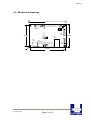
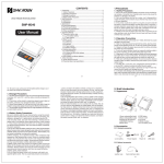
6.6 Mechanical drawings
77.0mm
1
CN1
Motor/Sense
CN5
Head
PRN609-S
44.0mm
1
1
CN3
RES
CN4
AUX IN
CN5
Cutter
1
CN5
Power
JP1
1
CN9
Serial RS232
CN8
AUX
1
71.0mm
11 March 2005
Page 31 of 31
50.0mm
CN5
USB1.1
1
MAN609-S
7 APPENDIX
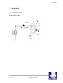
7.1 Application notes
High current output
11 March 2005
Page 32 of 32