1
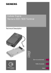
Cellular Engine
Siemens M20 / M20 Terminal
Technical Description
Data
Voice
SMS
FAX
V.24
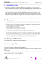
How to use this book
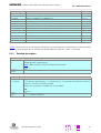
Table of contents
Index
Siemens Information and Communication Products
How to use this book
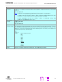
The following navigation tools are available in addition to the Acrobat Reader toolbar or short-cut menu (right
mouse key):
Click here when you see this hand.
Table of contents
1
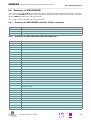
Overview ................................................................................................................... 11
2
Safety precautions for the user...............................................................................
2.1
Electrical safety..............................................................................................
2.2
Aircraft safety.................................................................................................
2.3
Environments with explosive substances ..................................................
12
12
12
12
Click here to jump to this section.
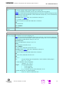
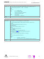
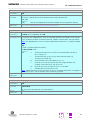
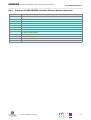
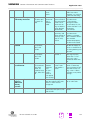
1
Feat_DCN
GSM 02.07
Called number display
The dialled digits are shown on the terminal’s
display (AT command terminal or display, if
connected) before signal transmission.
5.5.1
6.5
5.5.1
6.5.15
See “AT+CLCC List current calls of ME”
2
Feat_CPSind
Indication of call progress signals (in ac- GSM 02.07
cordance with GSM02.40)
The call progress is signalled on the display
and via audible tones after signal transmission.
See “AT+CLCC List current calls of ME”
Click here to jump to this section.
A
Click here to jump to the
Table of contents.
Version 5 dated 01.03.99
Click here to jump to
the Index.
Siemens Information and Communication Products
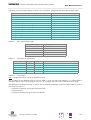
Table of contents
How to use this book .................................................................................................. 2
1 Overview
10
2 Safety precautions for the user
2.1 Electrical safety ..................................................................................................
2.2 Aircraft safety .....................................................................................................
2.3 Environments with explosive substances .......................................................
2.4 Safety on the road..............................................................................................
2.5 Non-ionizing radiation .......................................................................................
2.6 Electronics in medical equipment ....................................................................
2.7 Precautions in the event of loss/theft of the Cellular Engine
and the SIM card ................................................................................................
11
11
11
11
11
11
11
3 General product description M20
3.1 Teleservices ........................................................................................................
3.2 Data services.......................................................................................................
3.3 Mobile station features......................................................................................
3.4 Supplementary mobile station features ..........................................................
3.5 System requirements ........................................................................................
3.6 CE conformity .....................................................................................................
12
13
14
14
17
18
18
4 Hardware interfaces
4.1 Pin assignment of the 80-pole SMD connector...............................................
4.2 Power supply ......................................................................................................
4.3 Interfaces on the 80-pole SMD connector .......................................................
4.3.1 Specification of 2.8 V logic level .............................................................
4.3.2 Power on/off ..........................................................................................
4.3.3 Display ....................................................................................................
4.3.4 Keypad....................................................................................................
4.3.5 Serial Interface RS323 (V.24) Connections and signals ..........................
4.3.6 Additional RX/TX interface ......................................................................
4.3.7 Voiceband serial ports/digital audio interface (DAI) ................................
4.3.8 SIM card interface ..................................................................................
4.3.9 Power supply indicator ...........................................................................
4.4 Audio interface ...................................................................................................
4.5 Antenna interface...............................................................................................
19
19
20
20
20
21
22
23
23
25
25
27
27
28
29
5 AT command interface
5.1 Syntax of the standard AT commands.............................................................
5.2 Messages returned for normal data communication .....................................
5.3 Standard AT Hayes commands for controlling the M20 ................................
5.3.1 Detailed description................................................................................
5.4 AT commands and responses to GSM 07.07 and GSM 07.05........................
5.5 AT Cellular commands to GSM 07.07 ..............................................................
5.5.1 List of commands...................................................................................
5.5.2 Detailed description................................................................................
30
30
30
31
32
55
56
56
57
11
A
Version 5 dated 01.03.99
3
Siemens Information and Communication Products
5.6 AT commands to GSM 07.05 for SMS.............................................................. 88
5.6.1 List of commands................................................................................... 88
5.6.2 Detailed description................................................................................ 88
5.7 Siemens-defined AT commands for enhanced functions ............................ 103
5.7.1 List of commands................................................................................. 103
5.7.2 Detailed description.............................................................................. 103
5.8 Summary of CMS ERRORS.............................................................................. 119
5.8.1 Summary of CMS ERRORS related to V.25ter commands .................. 119
5.8.2 Summary of CME ERRORS related to GSM 07.07 .............................. 119
5.8.3 Summary of CME ERRORS related to GSM 07.05 .............................. 120
5.8.4 Summary of CMS ERRORS related to Siemens-defined commands... 121
6 Man Machine Interface
6.1 Overview ...........................................................................................................
6.2 Keypad address matrix ....................................................................................
6.3 Additional display information .......................................................................
6.4 MMI features and user-defined settings........................................................
6.5 MMI functions...................................................................................................
6.5.1 Putting into service...............................................................................
6.5.2 Handset answer functions – incoming seizure .....................................
6.5.3 Handset call functions – Outgoing seizure ...........................................
6.5.4 Clearing down – idle status ..................................................................
6.5.5 Dialling with abbreviated dialling keys ..................................................
6.5.6 Checking abbreviated dialling keys.......................................................
6.5.7 Programming abbreviated dialling keys ................................................
6.5.8 Redial....................................................................................................
6.5.9 Network call barring..............................................................................
6.5.10 Local call barring .................................................................................
6.5.11 Call forwarding....................................................................................
6.5.12 DTMF signalling..................................................................................
6.5.13 Reading an SMS message .................................................................
6.5.14 Deleting an SMS message .................................................................
6.5.15 SMS message overflow .....................................................................
6.5.16 Service indicator .................................................................................
6.5.17 Network selection ..............................................................................
6.5.18 SIM lock..............................................................................................
6.5.19 RSSI....................................................................................................
6.5.20 Ringer volume setting ........................................................................
6.5.21 Language volume setting ...................................................................
6.6 Power supply indicator....................................................................................
122
122
122
123
123
126
126
126
127
129
129
130
130
130
130
130
131
131
131
132
132
132
133
133
133
133
133
133
7 Peripheral devices
7.1 GSM antenna ....................................................................................................
7.2 SIM card reader ................................................................................................
7.3 SIM cards ..........................................................................................................
7.4 Handset .............................................................................................................
7.5 Sources for connectors....................................................................................
7.5.1 Antenna connector ...............................................................................
7.5.2 80-pole SMD connector........................................................................
7.6 Display ...............................................................................................................
134
134
134
136
136
137
137
137
138
A
Version 5 dated 01.03.99
4
Siemens Information and Communication Products
7.7 Keypad............................................................................................................... 138
8 Application notes
139
8.1 General notes ................................................................................................... 139
8.2 Getting started & Installation ......................................................................... 139
8.2.1 Connecting the M20T........................................................................... 139
8.2.2 Example circuit for IGNITION ............................................................... 140
8.2.3 Starting up and logging into the GSM net ............................................ 140
8.2.4 Hyperterminal: Setup (M20.ht) ............................................................. 141
8.2.5 Procomm Plus: Setup and activation.................................................... 141
8.2.5.1 Procomm Plus setup files:...................................................... 141
8.2.5.2 Start Procomm Plus................................................................ 142
8.2.6 Setting parameters ............................................................................... 142
8.2.6.1 Enter PIN1 .............................................................................. 142
8.2.6.2 Enter PUK1 ............................................................................. 142
8.2.6.3 Change PIN1........................................................................... 142
8.2.6.4 Lock/unlock PIN1 .................................................................... 143
8.2.6.5 Signal Quality .......................................................................... 143
8.2.6.6 Set all current parameters to manufacturer default................143
8.2.6.7 Store current parameter to user defined profile ..................... 143
8.2.6.8 Set all current parameters to user defined profile .................. 143
8.2.6.9 Display current configuration .................................................. 144
8.2.7 Phonebook handling ............................................................................. 144
8.2.7.1 Select phonebook................................................................... 144
8.2.7.2 Read phonebook entry ........................................................... 144
8.2.7.3 Select phonebook memory storage ....................................... 145
8.2.7.4 Write phonebook entry........................................................... 145
8.2.8 Phone call ............................................................................................. 146
8.2.8.1 Mobile originated call.............................................................. 146
8.2.8.2 Redial a number...................................................................... 146
8.2.8.3 Incoming call........................................................................... 146
8.2.8.4 Call a number stored in a phonebook ..................................... 146
8.2.9 Data transfer......................................................................................... 147
8.2.10 SMS with M20 to SIM (in text mode) ................................................ 147
8.2.10.1 Service centre number ......................................................... 147
8.2.10.2 Text mode ............................................................................147
8.2.10.3 Send SMS............................................................................. 147
8.2.10.4 Send SMS to e-mail address ................................................ 147
8.2.10.5 Send SMS to fax address ..................................................... 148
8.2.10.6 Store SMS in memory .......................................................... 148
8.2.10.7 List of all SMS of the memory.............................................. 148
8.2.10.8 Delete SMS message........................................................... 148
8.2.10.9 Send SMS stored in the memory ......................................... 148
8.2.10.10 Incoming SMS message..................................................... 148
8.2.10.11 Read SMS message ........................................................... 149
8.2.11 WinFaxPro setup ................................................................................ 149
8.2.12 Provider information ........................................................................... 150
A
Version 5 dated 01.03.99
5
Siemens Information and Communication Products
8.3 M20 diagnostics ............................................................................................... 151
8.3.1 Basics ................................................................................................... 151
8.3.2 Call setup.............................................................................................. 153
8.3.3 SW download ....................................................................................... 154
8.4 Serial interface configuration ......................................................................... 155
8.4.1 General information .............................................................................. 155
8.4.2 List of functions.................................................................................... 155
8.4.2.1 int BuildCommDCB(lpszDef, lpdcb)........................................ 155
8.4.2.2 int ClearCommBreak(idComDev)............................................ 156
8.4.2.3 int CloseComm(idComDev) .................................................... 157
8.4.2.4 BOOL EnableCommNotification(idComDev, hwnd, cbWriteNotify, cbOutQueue)
............................................................................................ 157
8.4.2.5 LONG EscapeCommFunction(idComDev, nFunction)............ 158
8.4.2.6 int FlushComm(idComDev, fnQueue) .................................... 159
8.4.2.7 int GetCommError(idComDev, lpStat) .................................... 160
8.4.2.8 UINT GetCommEventMask(idComDev, fnEvtClear)............... 161
8.4.2.9 int GetCommState(idComDev, lpdcb) .................................... 161
8.4.2.10 int OpenComm(lpszDevControl, cbInQueue, cbOutQueue). 162
8.4.2.11 int ReadComm(idComDev, lpvBuf, cbRead)......................... 164
8.4.2.12 int SetCommBreak(idComDev) ............................................ 164
8.4.2.13 UINT FAR* SetCommEventMask(idComDev, fuEvtMask)... 165
8.4.2.14 int SetCommState(lpdcb) ..................................................... 166
8.4.2.15 int TransmitCommChar(idComDev, chTransmit) .................. 167
8.4.2.16 int UngetCommChar(idComDev, chUnget) .......................... 167
8.4.2.17 int WriteComm(idComDev, lpvBuf, cbWrite) ....................... 168
8.5 SW download (Version update)...................................................................... 168
8.5.1 M20: HW setup .................................................................................... 168
8.5.2 M20Terminal ........................................................................................ 169
8.5.3 M20T: HW Setup ................................................................................. 169
8.5.4 M20T: Booting for SW loading ............................................................. 170
8.5.5 SW installation...................................................................................... 170
8.5.6 Starting FLASHV12............................................................................... 171
8.6 EMC-relevant information for integrators of the M20.................................. 172
8.7 Getting full-type approval with the application ........................................... 172
8.7.1 Basic configurations with FTA .............................................................. 172
8.7.2 Delta-type approval process ................................................................. 173
8.8 Application examples and reference circuits ................................................ 174
8.8.1 V.24 level converter.............................................................................. 174
8.8.2 6 V voltage supply from 12 V source.................................................... 174
8.8.3 SIM card reader connections................................................................ 175
8.8.4 Handset connection.............................................................................. 175
8.8.5 Adding echo suppression functionality................................................. 176
8.8.6 Ignition line ........................................................................................... 176
8.8.7 Reset: Deadlock handling ..................................................................... 177
8.9 Service information......................................................................................... 177
9 M20 Terminal
9.1 General information .........................................................................................
9.1.1 Features ...............................................................................................
9.1.2 Mechanical characteristics ...................................................................
178
178
178
179
A
Version 5 dated 01.03.99
6
Siemens Information and Communication Products
9.2 Electrical description and interfaces .............................................................. 179
9.3 Operation requirements, CE conformity, restrictions of use....................... 182
9.4 Full-type approval ............................................................................................ 182
10 M20 Development Box
183
11 Environmental requirements for the M20
183
12 EMC and ESD requirements
183
13 Migration M1 to M20
13.1 SW comparison ..............................................................................................
13.1.1 SMS mode .........................................................................................
13.1.2 AT-Commands: Functionality with new commands...........................
13.1.3 AT-Commands: Same functionality but changes in the parameters ..
13.2 System Parameter comparison (AT&V) on the M1 and M20.....................
183
183
183
184
185
185
14 References
187
15 Technical data
15.1 Technical data of the M20 .............................................................................
15.2 Design drawing of the M20 ...........................................................................
15.3 Design drawing of the M20 Terminal...........................................................
188
188
189
190
16 AT commands sorted by functionality
16.1 Commands for Call Control ...........................................................................
16.2 Commands for network services and status information..........................
16.3 Commands for supplementary network services .......................................
16.4 Commands for SIM ........................................................................................
16.5 Commands for interface to terminal equipment (TA – TE) ........................
16.6 Commands for device control.......................................................................
16.7 Commands for device Information...............................................................
16.8 Commands for SMS and CB (GSM 07.05)....................................................
16.9 Commands for data/fax .................................................................................
193
193
193
193
194
194
195
195
195
196
AT command summary .......................................................................................... 197
Abbreviations .......................................................................................................... 201
Index ......................................................................................................................... 203
A
Version 5 dated 01.03.99
7
Siemens Information and Communication Products
Figures
Fig. 3-1
Fig. 3-2
Fig. 4-1
Fig. 4-2
Fig. 4-3
Fig. 4-4
Fig. 4-5
Fig. 6-1
Fig. 7-1
Fig. 7-2
Fig. 7-3
Fig. 7-4
Fig. 7-5
Fig. 7-6
Fig. 7-7
Fig. 7-8
Fig. 8-7
Fig. 8-3
Fig. 8-4
Fig. 8-5
Fig. 8-6
Fig. 9-1
Fig. 9-2
Fig. 9-3
Fig. 15-1
Fig. 15-2
Fig. 15-3
Fig. 15-4
Fig. 15-5
Fig. 15-6
Design of the Siemens M20 ........................................................................ 12
M20 interface diagram ................................................................................. 18
Timing of power on/off signals ..................................................................... 21
Write timing of display interface .................................................................. 22
Read timing of display interface ................................................................... 22
Timing characteristics of DAI to microcontroller .......................................... 26
Timing characteristics of DAI to codec ......................................................... 26
Display structure ........................................................................................ 123
Big SIM Card Reader (L04) ......................................................................... 134
Mini SIM card reader (C707-1) ................................................................... 135
Mini SIM card reader (C707-3) ................................................................... 135
Mini SIM card reader (holder) ..................................................................... 135
Mini SIM card reader (connector) ............................................................... 135
SMR connector (straight) ........................................................................... 137
80-pole SMD connector (rigid) .................................................................... 137
80-pole SMD connector (floating) ............................................................... 137
Handsfree application diagram ................................................................... 176
Level converter ........................................................................................... 174
Voltage supply ............................................................................................ 174
SIM card connection pins ........................................................................... 175
Handset connection ................................................................................... 175
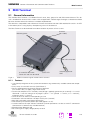
Modular Cellular Engine Siemens M20 Terminal ....................................... 178
Front view of Western plug 6-6 (male) ....................................................... 179
Front view of Western plug 4-4 (male) ....................................................... 180
Design drawing of the M20 ........................................................................ 189
M20 screw dimensions .............................................................................. 190
M20 Terminal front view ............................................................................ 190
M20 Terminal back view ............................................................................ 190
M20 Terminal top and side view ................................................................ 191
M20 Terminal bottom view ........................................................................ 192
Tables
Table 3-1
Table 3-2
Table 3-3
Table 4-1
Table 4-2
Table 4-3
Table 4-4
Table 5-1
Table 5-2
Table 5-3
Table 5-4
Table 5-5
Table 6-1
Table 6-2
Teleservices ................................................................................................. 13
Mobile station features ................................................................................ 16
Supplementary mobile station features ....................................................... 17
Pin assignment of the 80-pole SMD connector ........................................... 19
2.8 V logic level specification ....................................................................... 20
Timing values of display interface ................................................................ 23
Timing characteristics of DAI ....................................................................... 27
Standard Hayes AT commands .................................................................... 32
AT commands according to GSM 07.07 ...................................................... 57
AT commands according to GSM 07.05 ...................................................... 88
Siemens-defined AT commands ................................................................ 103
Summary of CMS ERRORS ....................................................................... 120
Keypad address matrix ............................................................................... 122
Description of keypad ................................................................................ 122
A
Version 5 dated 01.03.99
8
Table 6-3
Table 6-4
Table 6-5
Table 6-6
Table 6-7
Table 6-8
Table 6-9
Siemens Information and Communication Products
M20-specific MMI codes ........................................................................... 124
Languages for display text ......................................................................... 124
Value ranges ............................................................................................... 124
Basic MMI codes in accordance with ETS 300-511 ................................... 125
Teleservices ts ........................................................................................... 125
Changing the password in accordance with ETS 300-511 ......................... 125
Service indicator display ............................................................................. 132
A
Version 5 dated 01.03.99
9
1
Siemens Information and Communication Products
Overview
Overview
This document describes all the features, functions and interfaces of the Siemens M20 and M20 Terminal Cellular Engines. In addition, it states the base unit requirements which apply in connection with the operation of
M20/M20 Terminal.
M20 Terminal combines the functions of the M20 unit with all peripheral devices necessary for plug-and-play
usage (SIM card reader, V.24 serial Interface, Western plugs for handset and power supply) and a wide range
of supply voltages. For additional information on M20 Terminal, see Chapter 9 “M20 Terminal” on page 178.
This document also includes the list of AT commands implemented at the serial interface and describes the
MMI implemented at the display and keypad interface, the options for external M20 diagnostics, safety precautions for M20 users and M20 technical data .
In addition, this document provides service information and application notes and indicates the sources of
components necessary for operation e.g. SIM reader, handset, display and keypad.
Chapters on application notes with information on getting started, diagnostics and type approval complete this
document.
IMPORTANT:
This technical description applies to all M20 devices with version number
S30880-S8000-A100-1.
Users of the M20 are expressly requested to begin by reading the safety precautions in Chapter 2 “Safety precautions for the user” on page 11.
Information on finding out the software status is provided in Chapter 5.5 “AT Cellular commands to GSM 07.07”
on page 56 (AT+GMR, AT+CGMR).
If you have any technical questions regarding this document or the product described, please contact
your local distributor.
General information on cellular engines and a list of distributors can be found at the following Internet
addresses:
• English language: www.siemens.de/gsm_e
• Deutsche Sprache: www.siemens.de/gsm
A
Version 5 dated 01.03.99
10
2
Siemens Information and Communication Products
Safety precautions for the user
Safety precautions for the user
The following notes refer to the M20/M20 Terminal Cellular Engine AND to applications based on M20/M20
Terminal. The manufacturer of an application based on the M20/M20 Terminal must incorporate these safety
precautions in his/her instruction manual.
2.1
Electrical safety
The highest internal voltage applied to the M20 is 6 V; no special precautions are thus required to protect users
against high voltages (see Chapter 4.2 “Power supply” on page 20).
2.2
Aircraft safety
Cellular engines can interfere with an aircraft’s navigation system and its cellular network. The use of M20/
M20 Terminal on board aircraft is forbidden by law. Failure to comply with this prohibition may lead to temporary suspension or permanent cancellation of cellular engine services for the person who infringes this prohibition and/or to legal action against said person.
2.3
Environments with explosive substances
a) Users are advised not to use the device in automotive service stations.
b) Users are reminded of the necessity to comply with restrictions regarding the use of radio devices in fuel
depots, chemicals plants and locations where explosives are ignited.
2.4
Safety on the road
a) It is not permitted to signal incoming calls by sounding the vehicle’s horn or flashing the lights.
b) Drivers are advised not to use the hand-held microphone or the telephone handset while their vehicle is in
motion, except in the case of emergency. Use the handsfree facility to speak only if it does not divert your
attention from the traffic.
2.5
Non-ionizing radiation
As is the case with other mobile radio transmitters, operating personnel are advised to use the device in the
normal operating position only in order to ensure optimum performance and safety.
2.6
Electronics in medical equipment
Radio transmitters, including cellular engines, can interfere with the operation of inadequately protected medical devices. Please address all questions to a doctor or the manufacturer of the medical device.
2.7 Precautions in the event of loss/theft of the Cellular Engine and the
SIM card
If your M20/M20 Terminal, your SIM card or both go missing, notify your network operator immediately in order to avoid misuse.
A
Version 5 dated 01.03.99
11
3
Siemens Information and Communication Products
General product description M20
General product description M20
The Siemens M20 combines all the features required by developers and users. It is designed both for handling
complex industrial applications such as telemetry, telematics or communication, and for integration in stationary or mobile fields all over the world.
The most important features are:
• Top quality according to "normal mobile station" requirements (–104 dBm sensitivity) instead of "small
mobile station" requirements (–102 dBm sensitivity).
• Voice transmission with Enhanced Full Rate EFR and Full Rate FR
• Data transmission rate up to 14400 bit/s transparent and non-transparent
• Group 3 fax service
• SMS (text mode, PDU, MT, MO) and SMS Cell Broadcast
• Integrated echo suppression and noise reduction for handset
• Digital audio interface
• SIM Lock
• Network and service provider personalization according to GSM 02.22
• Reloadable software
• GSM900 phase II
• Compatible in terms of function and control with the GSM modules M1 and A1
• 2W power part (class 4)
• Single input voltage (6.0 V)
Average current: speech mode 200mA/idle mode 20mA
• Dimensions L x W x H in mm: 86.8 x 41.4 x 11.2.
• Weight: 38 g
• Temperature range: –20°C to +55°C
Note: Voltage supply: Voltage supply on connection must NOT rise faster than 3V/msec.
Additional features are listed below.
In addition to control via the serial interface, the Siemens M20 also offers the option of control by means of a
connected keypad and display.
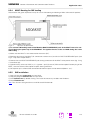
Using a board-to-board connector, the system integrator can integrate the components on the basic device’s
printed circuit board (e.g. hand-held devices like scanner).
All the main connections are already integrated in the Siemens M20 so that implementation can take place
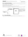
with only minimum development work.
Mounting holes
80 pole
SMD connector
Space for
SIM card reader
Antenna connector
Fig. 3-1
Design of the Siemens M20
A
Version 5 dated 01.03.99
12
Siemens Information and Communication Products
General product description M20
The Siemens M20 offers the following functions:
Additional Features:
• Dial tone
The SIEMENS M20 provides no dial tone at all or two permanently defined types of dial tone, as selected.
• Power management/backup routine
• DTMF
DTMF tones can be generated.
• PIN handling (protection can be activated/deactivated)
• Reload capability (software update)
Interfaces:
One serial interface (control, data transmission and software updates)
• SIM card reader interface for 3 V SIM cards.
• Analog interface for headset and microphone connection (telephone receiver)
• Digital Audio Interface (DAI)
Echo suppression for handsfree mode can be implemented by an external connection
• Ringer interface
Different ring volumes can be set
• Input port
The power supply status of the application can be signalled on the display (network operation, battery
operation, battery supply jeopardized, no display)
• Display interface
Display controller for dot display can be controlled (2 lines x 13 characters).
• Connector
All interfaces with the exception of the antenna (type: SMR nano) are fed out by means of a connector
on the hardware side. The connector is mechanically stable, the associated jacks can be purchased
and installed worldwide by the integrators.
• Interface for a keypad with 4 x 6 keyboard matrix.
• Interface to a tuning fork contact (hookswitch)
• Power supply
• On switch
3.1
Teleservices
No
GSM standard Teleservice
Reference
Available
via AT+C
Available
via MMI
1
2
TS11
TS12
Telephony
Emergency Call
GSM 02.03 A.1.1
GSM 02.03 A.1.2
5.3
6.5
5.3
6.5
3
TS21
Short Message MT/PP
GSM 02.03 A.1.3
5.6
6.5.13
4
5
TS22
TS23
Short Message MO/PP
SMS Cell Broadcast
GSM 02.03 A.1.3.1 5.6
GSM 02.03 A.1.3.2 5.6
–
6
TS62
Teleservice Automatic G3 fax
GSM 02.03 A.1.5
–
Table 3-1
6.5.13
5.5
Teleservices
A
Version 5 dated 01.03.99
13
3.2
Siemens Information and Communication Products
General product description M20
Data services
Terminal adapter (TA) – terminal equipment (TE) interface:
RS232 compatible:
Baud rates: 2400, 4800, 9600, 14400, 19200, 28800, 33600 and 57600.
No automatic baud rate adjustment. Default: 19200 (can be adjusted by AT+IPR). See “AT+IPR Set fixed local
rate”.
Data stacks:
Transparent data/non-transparent data
On-air channels: TCH/9.6F, TCH/4.8F, TCH/2.4F. See “AT+CBST Select Bearer Service Type”.
V.42bis data compression (can be adjusted with “AT+DR V.42bis data compression reporting control” on page 48).
Transparent fax
Class 1 group 3 supported.
On-air channels: TCH/9.6F, TCH/4.8F, TCH/2.4F. See “AT+CBST Select Bearer Service Type”.
3.3
Mobile station features
No Mnemonic1)
Mobile station feature3)
1
Called number display
GSM 02.07
The dialled digits are shown on the terminal’s
display (AT command terminal or display, if connected) before signal transmission
Feat_DCN
Ref.
Available
via AT+C
Available
via MMI
5.5.1
6.5
See “AT+COLP Connected line identification presentation”.
2
Feat_CPSind
Indication of call progress signals (in ac- GSM 02.07
cordance with GSM02.40)
The call progress is signalled on the display and
via audible tones after signal transmission.
–
6.5.16
3
Feat_PLMNind
Country/PLMN indication
GSM 02.07
The network operator is shown on the display
after successful logon to the PLMN (MS idle).
See “AT+COPS Operator selection”.
5.5.1
6.4
4
Feat_PLMNsel
Country/PLMN selection
GSM 02.07
Automatic and manual network operator selection. See “AT+COPS Operator selection”.
5.5.1
6.3
5
Feat_Keypad
Keypad
GSM 02.07
Keys are permanently assigned to their logical
functionality, i.e. programmable function keys
or soft keys are not implemented.
• 0, 1, 2, 3, 4, 5, 6, 7, 8, 9, *, # keys send
key
• 4 abbreviated dialling keys are used in
the current keypad matrix
• redial/cursor up
• SMS key
• + (for settings)
• – (for settings)
–
6.2
A
Version 5 dated 01.03.99
14
Siemens Information and Communication Products
No Mnemonic1)
Mobile station feature3)
6
Feat_IMEI
7
Feat_SMoverflow
8
Feat_DTE_DCE
General product description M20
Ref.
Available
via AT+C
Available
via MMI
IMEI – International Mobile Equipment GSM 02.07
Identity
An unique international identity code (IMEI) is
stored in the terminal. This code is individually
assigned to each terminal by the terminal manufacturer. See “AT+CGSN Request product serial
number identification (IMEI) identical to GSN”.
Short message overflow indication
GSM 02.07
Messages from the Short Message telephone
service are saved on the SIM. The number of
messages that can be saved depends on the
SIM card used. An advisory is output if there is
insufficient memory available for an incoming
message. See “AT^SMGO Set or query SMS overflow presentation mode or query SMS overflow”.
5.5.1
6.4
5.7.1
6.3
DTE /DCE interface
GSM 02.07
Modem interface between data terminal equipment and data circuit terminating equipment
See “AT+IFC Set TE-TA local data flow control”, See
“AT+IPR Set fixed local rate”, See “AT+ILRR Set
TE-TA local rate reporting mode”, See “AT+ICF Set
5.3
–
5.5.1
6.5
5.5.1
6.3
5.5.1
6.5.12
TE-TA control character framing”
9
Feat_IntAccess
10 Feat_ServInd
11 Feat_DTMF
International access function
GSM 02.07
The international access code to the PSTN
(Public Switched Telephone Network) is dialled
by holding down the <0> key until ‘+’ appears
on the display (nominal time approx. 1 second).
The access code, thus, does not depend on the
location (international roaming).
The international access code can also be dialled using the conventional country-specific
prefix (e.g. 00 in Austria, Germany). See “ATD
Mobile originated call to dial a number”.
Service indicator
GSM 02.07
The call processing status of the terminal is
shown on the display when the terminal is idle.
See “AT+CREG Network registration”.
Dual-tone multifrequency function
GSM 02.07
If you press the signal key during an existing
connection, a DTMF signal is transmitted to the
remote station. The digits entered between signal transmission and call pickup are rejected.
DTMF digits are not saved on repertory dialling
keys. See “AT+VTS DTMF and tone generation
(<Tone> in {0-9, *, #, A, B, C, D})”.
A
Version 5 dated 01.03.99
15
Siemens Information and Communication Products
General product description M20
No Mnemonic1)
Mobile station feature3)
12 Feat_SIM
Subscription identity management
GSM 02.07
The IMSI (International Mobile Subscriber Identity) is used for internal signalling and is saved
on the SIM (processor card). If the SIM is removed from the terminal, any existing connections are cleared down and further call setup is
prevented (exception: emergency calls). See
Ref.
Available
via AT+C
Available
via MMI
5.5.1
6.5
y (off)
–
“AT+CIMI Request international mobile subscriber
identity”.
13 Feat_OnOff
On/off switch 2)
GSM 02.07
Switch off is implemented only via AT commands. See “AT^SMSO Switch off mobile station
turn off”.
14 Feat_A51
15 Feat_A52
Support of encryption A5/1
Support of encryption A5/2
GSM 02.07
GSM 02.07
5.5.1
6.5
5.5.1
6.5
16 Feat_SMS_CB_DRX
Short Message Service Cell Broadcast DRX GSM 02.07
DRX: discontinuous reception (mechanism).
5.5.1
–
See “AT+CSCB Select cell broadcast SMS messages”.
17 Feat_AD
Abbreviated dialling
GSM 02.07
Abbreviated dialling keys (in MMI) or via index
numbers in phone book (AT+C), to be programmed by the customer.
See “ATD Mobile originated call to dial a number”.
5.5.1
6.5.5
18 Feat_FND
Fixed number dialling
GSM 02.07
Only implemented via AT command interface
since the MMI has no phone book implemented. See “ATDS Dial stored phone number in MEphonebook”.
5.5.1
–
19 Feat_BO
Barring of outgoing calls
GSM 02.07
Supported locally on the terminal
(see supplementary service ‘Barring of all outgoing calls’). See “AT+CLCK Facility lock”.
Last numbers dialled
GSM 02.07
5.5.1
6.5.9
5.5.1
6.5.8
5.5.1
6.1
20 Feat_LND
The last number dialled is displayed and an outgoing seizure is initiated when you lift the handset and press the redial key.
See “ATDL Redial last telephone number used”.
21 Feat_HumanInterface Human interface provided
• Display
• Key-Pad
• Buzzer
• Audio-Tones
GSM 02.07
Note:
1
) "Mnemonic" defines the service name accord. to GSM standards
2
) Depending on application
3
) The features are defined in GSM 02.07 Version 5.1.0.: July 1996 (Annex B).
Table 3-2
Mobile station features
A
Version 5 dated 01.03.99
16
3.4
Siemens Information and Communication Products
General product description M20
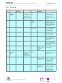
Supplementary mobile station features
No Abbrevia- Feature
tions
1
CLIP
Calling Line Identification Presentation
Reference
Available
via AT+C
Available
via MMI
GSM 02.04 3.1
5.5.1
6.5
GSM 02.04 3.1
5.5.1
6.5
GSM 02.04 3.1
5.5.1
–
GSM 02.04 3.1,
5.5.1
6.5
5.5.1
6.5
5.5.1
6.5
5.5.1
6.5
GSM 02.04 3.1
5.5.1
–
GSM 02.04 3.1
5.5.1
–
GSM 02.04 3.1
5.5.1
–
GSM 02.04 3.1
5.5.1
–
GSM 02.04 3.1
5.5.1
–
GSM 02.04 3.1
5.5.1
–
5.5.1
6.5
5.5.1
6.5
5.5.1
6.5
5.5.1
6.5
5.5.1
6.5
See “AT+CLIP Calling line identification presentation”.
2
CLIR
Calling Line Identification Restriction
See “AT+CLIR Calling line identification restriction”.
3
COLP
Connected Line Identification Presentation
See “AT+COLP Connected line identification
presentation”.
4
CFU
Call Forwarding Unconditional
See “AT+CCFC Call forwarding number and con- GSM 02.07 2.1
ditions control”.
5
CFB
Call Forwarding on Mobile Subscriber Busy
GSM 02.04
3.1,
See “AT+CCFC Call forwarding number and con- GSM 02.07 B 2.1
ditions control”.
6
CFNRy
Call Forwarding on No Reply
GSM 02.04
3.1,
See “AT+CCFC Call forwarding number and con- GSM 02.07 B2.1
ditions control”.
7
CFNRc
Call Forwarding on Mobile Subscriber Not GSM 02.04 3.1,
Reachable
GSM 02.07 B2.1
See “AT+CCFC Call forwarding number and conditions control”
8
CW
Call Waiting
See “AT+CCWA Call waiting control”.
9
CH
Call Hold
See “AT+CHLD Call hold and multiparty”.
10
MTPy
Multiparty Service
See “AT+CHLD Call hold and multiparty”.
11
CUG
Closed User Group
See “AT+CCUG Closed user group control”
12
AoC
Advice of Charge (Information)
See “AT+CAOC Advice of Charge information”
13
AoC
Advice of Charge (Charging) 1)
See “AT+CAOC Advice of Charge information”
14
BAOC
Barring of All Outgoing Calls
GSM 02.04 3.1,
GSM 02.07 B.2.1
Barring of Outgoing International Calls
GSM 02.04 3.1,
GSM 02.07 B.2.1
See “AT+CLCK Facility lock”
Barring of Outgoing International Calls ex- GSM 02.04 3.1,
cept those directed to the Home PLMN GSM 02.07 B.2.1
Country. See “AT+CLCK Facility lock”
Barring of All Incoming Calls
GSM 02.04 3.1,
GSM 02.07 B.2.1
See “AT+CLCK Facility lock”
Barring of Incoming Calls when Roaming GSM 02.04 3.1,
Outside the Home PLMN Country
GSM 02.07 B.2.1
See “AT+CLCK Facility lock”
15
BOIC
16
BOIC
17
BAIC
18
BAIC
19
USSD
See “AT+CLCK Facility lock”
Unstructured SS Data
GSM 02.30, GSM
02.07B.2.1
6.5
Note: 1) Prepaid SIM cards, no MMI for charge query
Table 3-3
Supplementary mobile station features
A
Version 5 dated 01.03.99
17
3.5
Siemens Information and Communication Products
General product description M20
System requirements
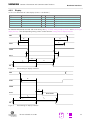
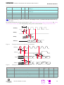
The M20 is designed for use in a system environment comprising a GSM900 mobile radio network with one
or more network operators per country. A corresponding infrastructure for a configuration level suitable for the
use of terminal devices with 2 watts transmitting power is a basic requirement.
The functional environment for the M20 is constituted by a so-called base unit which supports the interfaces
of the M20 (see Fig. 3-2 M20 interface diagram). The base unit must support at least 6 V power supply, a SIM
card interface and an AT command interface via the serial interface (V.24) or Man Machine Interface (MMI).
The base unit can be, for example, a GSM telephone, a ticket machine, some kind of vending machine, a handheld device or another terminal device which uses the GSM as a medium for transmitting voice, fax/data or
short messages (SMS). The precondition is that the base unit has to support the interfaces for the M20 operation as laid down in this technical description.
Antenna
Keypad*
4x6 Matrix
SIM-Reader
Hook-switch
M20
Handset*
SIM
6V
Power supply
Buzzer*
Dot-Display*
2lines 16char
Serial Interface (RS232 / V24)
Digital Audio Interface /
Voiceband Serial Interface
Power supply indicator*
Fig. 3-2
3.6
*Man Machine Interface
M20 interface diagram
CE conformity
The M20 bears the CE symbol of conformity. This symbol guarantees the compliance of the design and implementation of the M20 with the currently valid versions of the following EC directives.
• 89/336/EC (EMC Directive)
• 73/23/EC (Low Voltage Directive)
• 91/263/EC (Telecommunications Terminals Directive)
Standards:
• EMC: ETS 300 342-1
• Safety: EN 60950
• GSM network: TBR 19, TBR 20
A
Version 5 dated 01.03.99
18
4
Siemens Information and Communication Products
Hardware interfaces
Hardware interfaces
4.1
Pin assignment of the 80-pole SMD connector
The location of PIN 1 is shown in “Design drawing of the M20”.
Parallel display data bus
Pin 1
Parallel display data bus
Pin 2
Parallel display data bus
Pin 3
Parallel display data bus
Pin 4
Parallel display data enable
Pin 5
Parallel display write
Pin 6
Reset
Pin 7
Ignition
Pin 8
Clear to send
Pin 9
Receive data
Pin 10
Ring indication
Pin 11
VSB to/from controller
Synchronisation
Pin 12
VSB to/from controller clock
Pin 13
VSB to/from controller data input
Pin 14
VSB to/from controller data output Pin 15
Data terminal ready
Pin 16
Ground
Ground
Pin 17
Pin 18
Pin 19
Pin 20
Pin 21
Pin 22
Pin 23
Pin 24
Pin 25
Data set ready
Pin 26
SIM card reset
Pin 27
SIM card data
Pin 28
6 V Power supply
6 V Power supply
6 V Power supply
6 V Power supply
6 V Power supply
Ground
Ground
Reserved pin
Pin 29
Download enable
Pin 30
not connected
Pin 31
Keypad column 2
Pin 32
Keypad column 0
Pin 33
Keypad row 4
Pin 34
Keypad row 2
Pin 35
Keypad row 0
Pin 36
Hookswitch
Pin 37
Ground
Pin 38
Microphone minus
Pin 39
Speaker minus
Pin 40
Table 4-1
Site on PCB
D14
D15
D12
D13
D10
D11
D8
D9
DE
DRS
HWR#
DCS#
RES#
POWER_ON
IGNITION
USCRTS
USCCTS
USCTX
USCRX
RXDATA
USCRI
TXDATA
VSFS_C
VSFS_V
VSCLK_C
VSDI_C
VSDO_C
DTR
GND
DC_IN
DC_IN
DC_IN
DC_IN
DC_IN
GND
GND
GND
DSR
CCRST
CCIO
GPCS
BOOTCODEEN
NC
KPC2
KPC0
KPR4
KPR2
KPR0
HOOKSW
GND
MICN
SPN
VSCLK_V
VSDO_V
VSDI_V
GND
GND
GND
DC_IN
DC_IN
DC_IN
DC_IN
DC_IN
GND
GND
CCCLK
DCD
CCIN
CCVCC
GPIO1
GPIO0
KPC3
KPC1
KPR5
KPR3
KPR1
BUZZER
GND
MICP
SPP
Pin 80
Parallel display data bus
Pin 79
Parallel display data bus
Pin 78
Parallel display data bus
Pin 77
Parallel display data bus
Pin 76
Parallel display address (A0)
Pin 75
Parallel display chip select
Pin 74
Power on indication
Pin 73
Request to send
Pin 72
Transmit data
Pin 71
2. serial interface receive data
Pin 70
2. serial interface transmit data
Pin 69
VSB to/from codec
Synchronisation
Pin 68
VSB to/from codec clock
Pin 67
VSB to/from codec data output
Pin 66
VSB to/from codec data input
Pin 65
Pin 64
Pin 63
Pin 62
Pin 61
Pin 60
Pin 59
Pin 58
Pin 57
Pin 56
Ground
Ground
Ground
6 V Power supply
6 V Power supply
6 V Power supply
6 V Power supply
6 V Power supply
Ground
Ground
Pin 55
SIM card clock
Pin 54
Data carrier detect
Pin 53
SIM card inserted
Pin 52
SIM card supply
Pin 51
Battery load indicator
Pin 50
Supply source indicator
Pin 49
Keypad column 3
Pin 48
Keypad column 1
Pin 47
Keypad row 5
Pin 46
Keypad row 3
Pin 45
Keypad row 1
Pin 44
Buzzer
Pin 43
Ground
Pin 42
Microphone plus
Pin 41
Speaker plus
Pin assignment of the 80-pole SMD connector
A
Version 5 dated 01.03.99
19
Siemens Information and Communication Products
Hardware interfaces
The interfaces are described in detail in Chapters 4.2 “Power supply” on page 20, 4.3 “Interfaces on the 80-pole
SMD connector” on page 20 and 4.4 “Audio interface” on page 28.
Note: Unused pins
• In all cases in which the DAI is not used, the voiceband serial connector to/from controller has to be
connected externally to the voiceband serial connector to/from codec. Connection wires should be
as short as possible (10 cm maximum)
Connect VSFS_V to VSFS_C, VSCLK_V to VSCLK_C, VSDO_V to VSDI_C, VSDI_V to VSDO_C. For additional information, see also Chapter 8.8.5 “Adding echo suppression functionality” on page 176.
• RXDATA must be connected to RES#, if not used.
• The following pins (if unused) shall be:
connected to GND: CCIN
connected to a 10 kOhm - 100 kOhm pull-down (ground) resistor: BOOTCODEEN, GPIO0, GPIO1,
HOOKSW
not connected: all display pins, all keypad pins, USCxxx, MICN, MICP, BUZZER, SPN, SPP,
POWER_ON, RES#, DSR, DCD, TXDATA, DTR, GPCS.
• All DC_IN pins and all GND pins shall be used!
• The maximum number of push-pull cycles of the SMD connector shall not exceed 100.
4.2
Power supply
Single voltage power supply:
Current consumption:
Switch-in current pulse
(when voltage is applied)
6V +/- 0.2 V
max. 2A pulses.
Imax = 15 A, duration: approx. 10 µs,
decreasing (1/e) time constant <90 µs at Rsupply<0.1Ω
decreasing time to stand-by current value: < 300 µs
I ≤ 0.2 mA
Stand-by state
(voltage is applied, ignition not yet asserted)
Idle mode
I < 20 mA average
typ. 14 mA average (depends on network operator)
Call in progress
I < 2A (pulsed t = 577 ms at T = 4.615 ms)
typ. 1.5 A for performance class 5
arithmetic mean: I < 250 mA
4.3
Interfaces on the 80-pole SMD connector
This chapter describes all interfaces (except power supply) on the 80-pole SMD connector.
4.3.1
Specification of 2.8 V logic level
The following diagram shows the 2.8 V logic level specification used in the M20:
Parameter
Min.
Max.
VoH output high voltage
VoL output low voltage
2.3 V
0V
2.9 V
0.4 V
ViH input high voltage
2.1 V
3V
ViL input low voltage
-0.3 V
0.8 V
Table 4-2
2.8 V logic level specification
A
Version 5 dated 01.03.99
20
4.3.2
Siemens Information and Communication Products
Hardware interfaces
Power on/off
Signal
Function
IGNITION
Switch on
POWER_ON
Power-on indicator
I/O
Level
Comments
I
1
)
IGNITION >2.7 V for longer than 1 s switches on
O
2
)
Load current < 300 uA
Note: may be unconnected if unused
RES#
Reset indicator
O
2.8V
Load current < 500 uA
Note: may be unconnected if unused
Note:
1
) Level range: 0 < IGNITION < 6.2 V, (maximum voltage: +/-50 V). For additional information see 8.8.6 “Ignition
line” on page 176.
2
) See Fig. 4-1 Timing of power on/off signals case IGNITION > 2.7 V level = IGNITION – 0.7 V.
To turn on the M20, connect IGNITION to the voltage specified in the table above. The device will then keep
running even if a voltage < 0.6 V is applied to IGNITION or the device is left disconnected. To turn off the M20,
use the corresponding AT command (AT^SMSO, see Chapter 5.7 “Siemens-defined AT commands for enhanced
functions” on page 103).
Note: if IGNITION is connected to a fixed voltage > 1.3 V, the M20 cannot be turned off with an AT command.
POWER_ON indicates that the microprocessor of M20 is supplied.
RES# level High indicates that the microprocessor of M20 is supplied and working.
Note: RES# also can be used as 2.8 V reference level for applications of the M20.
For additional information, see Fig. 4-1 Timing of power on/off signals.
IGNITION
Uswitchon
t
duration > 1s
RES#
2.8V
t
300ms
POWER_ON
Uswitchon-0.7V
2V typ.
t
Fig. 4-1
Timing of power on/off signals
A
Version 5 dated 01.03.99
21
4.3.3
Siemens Information and Communication Products
Hardware interfaces
Display
12 Pins for connection of a dot display (2 lines x 16 columns)
Signal
DCS#
DRS
DE
D8..D15
HWR#
Function
Chip select
Address (A0)
Data enable
Databus
Write
I/O
O
O
O
I/O
O
Level
2.8V
2.8V
2.8V
2.8V
2.8V
Comments
may be disconnected if unused
may be disconnected if unused
may be disconnected if unused
may be disconnected if unused
may be disconnected if unused
For detailed information on read and write timing see Fig. 4-2 Write timing of display interface and Read timing of
display interface. The corresponding timing values can be found in Timing values of display interface.
DRS
t13
t14
t15
t16
DCS#
HWR#
t17
t18
D15:8
t10
t19
t11
t12
DE
Fig. 4-2
Write timing of display interface
DRS
t21
DCS#
HWR#
t22
D15:8
DATA VALID
t20
t12
t11a
t23
DE
Fig. 4-3
Read timing of display interface
A
Version 5 dated 01.03.99
22
Parameter
t10
t11
t12
t13
t14
t15
t16
t17
t18
t11a
t19
t20
t21
t22
t23
Table 4-3
4.3.4
Siemens Information and Communication Products
Comment
Write high byte to display enable high
Display enable high width
Display enable low width
Display register select setup
Display register select hold
Display chipselect setup
Display chipselect hold
Data setup
Data hold
Display enable high width read extension
Display enable low to write high
Display register select to display enable high
Display chipselect to display enable high
Display enable high to data valid
Data hold
Hardware interfaces
Min.
Typ.
152
Max.
462
462
10
5
10
5
68
15
538
10
200
200
450
0
Units
ns
ns
ns
ns
ns
ns
ns
ns
ns
ns
ns
ns
ns
ns
ns
Timing values of display interface
Keypad
10 Pins for 4*6 keypad matrix.
Signal
KPR0..5
KPC0..3
Function
Keypad row
Keypad column
I/O
I
O
Level
2.8 V
2.8 V
Comments
may be disconnected if unused
may be disconnected if unused
For activation of a key, connect a row signal to the appropriate column signal. The keypad address matrix implemented in the MMI software can be found in Chapter 6.2 “Keypad address matrix” on page 122.
Note: maximum input speed: 1 key per 400ms
4.3.5
Serial Interface RS323 (V.24) Connections and signals
The Serial Interface can be used for:
• AT command interface
• Software download (SW update), see 8.5 “SW download (Version update)” on page 168
• serial interface for data/fax/SMS services.
Note:
External level converter is necessary for V.24 level when using the M20.
The M20T has a direct 9 pin serial interface port.
A
Version 5 dated 01.03.99
23
Siemens Information and Communication Products
Hardware interfaces
General Note:
1) Signal levels on the M20T: 5-15V
2) Signal levels on the M20: 2,8 V
3) Crossing out of signal lines is done inside the M20T so that the M20T can be connected to the PC directly
using a standard non-crossover serial cable.
4) Applications directly connecting to the M20 need to cross out the signal paths as shown in the above figure.
Note: If a Pin is not used it can stay unconnected
A
Version 5 dated 01.03.99
24
Siemens Information and Communication Products
Hardware interfaces
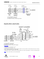
Signal description on the 9-pole D-sub DCE connector:
9-pole D-Sub
DCE Pin Nr
1
2
3
4
5
6
7
8
9
Descr.
Function
DCD
RXD
TXD
DTR
GND
DSR
RTS
CTS
RI
Data Carrier Detect
Receive Data
Transmit Data
Data Terminal Ready
Ground
Data set ready
Request to send
Clear to send
Ring Indication
CCITT
V-24
109
104
103
108
102
107
105
106
125
EIA
RS232
CF
BB
BA
CD
AB
CC
CA
CB
CE
DIN
66020
M5
D2
D1
S1
E2
M1
S2
M2
M3
I/O DCE to
DTE
O
O
I
I
O
I
O
O
Signal connection 9-pole D-sub DCE to M20 80-pole SMD connector:
DCE Pin Nr
1
2
3
4
5
6
7
8
9
4.3.6
DCE Signal
DCD
RXD
TXD
DTR
GND
DSR
RTS
CTS
RI
M20 Signal
DCD
USCTX
USCRX
DSR
M20 Pin Nr
54
72
10
26
DTR
USCCTS
USCRTS
USCRI
16
9
73
11
Additional RX/TX interface
This interface is reserved for Siemens development internal purposes.
Signal
RXDATA
TXDATA
4.3.7
Function
Receive data
Transmit data
I/O
I
O
Level
2.8 V
2.8 V
Comments
if unused, connect to signal RES#
may be disconnected if unused
Voiceband serial ports/digital audio interface (DAI)
To provide a digital audio interface to the user and to offer high-end echo suppression in handsfree environments as an upgrade feature, the on-board voiceband serial connector between the M20 microcontroller and
codec (A/D device) is connected to the 80-pole SMD connector.
Note: the data exchanged on the interface involves 13 bit linear PCM at 8000 samples per second.
Note: in normal cases, the voiceband serial ports (to microcontroller and to codec) have to be interconnected
on the PCB of the base unit.
If using the DAI, connection to the codec-oriented ports is not necessary.
For handsfree applications, see detailed information in Chapter 8.8.5 “Adding echo suppression functionality” on
page 176.
Signal
VSFS_C
Function
Synchronisation
I/O
I
Level
2.8V
VSCLK_C
Clock
I
2.8V
Comments
to microcontroller (in normal cases, to be connected to
VSFS_V)
to microcontroller (in normal cases, to be connected to
VSCLK_V)
A
Version 5 dated 01.03.99
25
Siemens Information and Communication Products
VSDO_C
Data output
O
2.8V
VSDI_C
Data Input
I
2.8V
VSFS_V
VSCLK_V
VSDO_V
VSDI_V
Synchronisation
Clock
Data output
Data Input
O
O
O
I
2.8V
2.8V
2.8V
2.8V
Hardware interfaces
to microcontroller (in normal cases, to be connected to
VSDI_V)
to microcontroller (in normal cases, to be connected to
VSDO_V)
to codec
to codec
to codec
to codec
Note: data clock (VSCLK_C, VSCKL_V): 104 kHz, word length: 13 bits, synchronisation pulse rate (VSFS_C,
VSFS_V): 8 kHz.
For detailed information on timing characteristics, see Timing characteristics of DAI to microcontroller and Timing
characteristics of DAI to codec.The corresponding timing values can be found in Timing characteristics of DAI.
t90
VSCLK (I)
t92
t91
VSFS (I)
t94
t93
VSDI (I)
D15
D14
t95
VSDO (O)
Fig. 4-4
D15
D14
D13
Timing characteristics of DAI to microcontroller
VSCLK (O)
t47
t48
VSFS (O)
t43
t44
D15
VSDI (I)
D14
t50
VSDO (O)
Fig. 4-5
Parameter
t43
t44
t47
t48
t49
t50
D4
D3
D15
t49
D15
D14
D4
D3
D15
Timing characteristics of DAI to codec
Comment
VSDI setup time before VSCLK low
VSDI hold time after VSCLK low
VSFS delay from VSCLK high
VSFS hold time after VSCLK high
VSDO hold time after VSCLK high
VSDO delay from VSCLK high
Min.
25
10
Typ.
Max.
25
-20
-20
20
Units
ns
ns
ns
ns
ns
ns
A
Version 5 dated 01.03.99
26
t90
t91
t92
t93
t94
t95
Table 4-4
4.3.8
Siemens Information and Communication Products
VSCLK period
VSFS setup time before VSCLK low
VSFS hold time after VSCLK low
VSDI setup time before VSCLK low
VSDI hold time after VSCLK low
VSDO delay after VSCLK high
Hardware interfaces
9615
4
7
4
7
0
15
ns
ns
ns
ns
ns
ns
Timing characteristics of DAI
SIM card interface
In general the SIM interface is specified in GSM 11.11.
Note: the M20 supports 3V SIM cards.
Signal
CCVCC
CCRST
CCIO
CCCLK
CCIN
Function
SIM card power supply
SIM card Reset
SIM card data in/out
SIM card clock
SIM card Inserted switch
GND
Ground
I/O
O
O
I/O
O
I
Level
2.8 V
2.8 V
2.8 V
2.8 V
2.8 V
0V
Comments
Contact C1 1)
Contact C2 1)
Contact C7 1)
Contact C3 1)
must be connected to GND, if SIM card reader does
not provide a CCIN switch. 2)
Contact C5 1)
Notes:
1
) All information provided on the SIM card interface complies with GSM 11.11 and 11.12.
Contacts C4, C6 and C8 are not provided by M20.
2
) When using a SIM card reader without a CCIN switch, SIM card removal must be avoided when voltage is
applied to the M20. This should be avoided by the mechanical integration of the SIM card reader in the application.
4.3.9
Power supply indicator
The power supply indicator is only used by the inbuilt MMI software. This allows the M20 MMI software to
indicate the actual base unit power supply status on the display.
Note: this functionality is not available when controlling the M20 via the AT command interface.
Signal
GPCS
Function
GP chip select
I/O
O
Level
2.8 V
Comments
reserved
may be disconnected if unused
GPIO0
GP port pin 0
I
2.8 V
GPIO1
GP port pin 1
I
2.8 V
Supply source indicator (by mains or battery)
if unused, connect to a 10kOhm - 100 kOhm pull-down resistor
Battery load indicator (full or below warning level)
if unused, connect to a 10kOhm - 100 kOhm pull-down resistor
GPIO 1
0
0
1
1
GPIO 0
0
1
0
1
Description
Base unit supplied by mains, battery full (= normal state)
Base unit supplied by battery, battery full
Base unit supplied by mains, battery voltage below warning level
Base unit supplied by battery, battery voltage below warning level
A
Version 5 dated 01.03.99
27
4.4
Siemens Information and Communication Products
Hardware interfaces
Audio interface
Signal
MICP
MICN
Function
Microphone plus
I/O Level
I
Microphone minus I
Vpp(V): 1)
typ.: 1.0954 / Fscale
max.: 1.578 / Fscale
Vpp(V): 1)
typ.: 1.0954 / Fscale
max.: 1.578 / Fscale
Vpp(V):
nom.: 2.1909
max.: 3.156
SPP
Speaker plus
O
SPN
Speaker minus
O
Vpp(V):
nom.: 2.1909
max.: 3.156
BUZZER
Buzzer
O
1.2 V - 1.35 V
I
2.8 V
Comments
Differential input; must be AC-coupled;
input resistance: 11–22 MΩ
Note: may be disconnected if unused
Differential Input; internally; must be AC-coupled;
input resistance: 11–22 MΩ
Note: may be disconnected if unused
min. load resistance: 32 Ω
max. load capacitance: 100 pF
should be AC-coupled
Note: may be disconnected if unused
min. load resistance: 32 Ω
max. load capacitance: 100 pF
should be AC-coupled
Note: may be unconnected if unused
> 2 kOhm, < 50 pF,
used only with integrated MMI
Note: may be disconnected if unused
HOOKSW Hookswitch
used only with integrated MMI
ON-HOOK = 0V
OFF-HOOK = 2.1 - 3 V
if unused, connect to a 10 kOhm - 100 kOhm pull-down
resistor
Note:
1
) Fscale = 10^((3*inBbcGain)/20) (for parameter "inBbcGain", see description of command AT^SNFI in Chapter
5.7 “Siemens-defined AT commands for enhanced functions” on page 103)
The microphone should comply with the following technical data:
-37 ± 2 dB (500 Hz, 0 dB = 1 V/Pa, v = 0)
Sensitivity
Impedance
2 kΩ ± 30 % (1 kHz)
Bias voltage
Input current
1.5 V DC (1–10 V DC)
≤ 300 µA
Signal-to-noise ratio
≤ 66 dB
Technical data of the speaker:
Volume
(97.0 ± 2) dB SPL
Impedance
THD
150 ± 30 Ω
≤ 4 % (800 Hz, 104 dB SPL)
≤ 2 % (300–3400 Hz, 94 dB SPL)
A
Version 5 dated 01.03.99
28
4.5
Siemens Information and Communication Products
Hardware interfaces
Antenna interface
The antenna must satisfy the following electrical requirements:
Frequency, TX
Frequency, RX
890-915 MHz
935-960 MHz
Impedance
50 Ω
VSWR
TX: max. 1.7:1 installed
RX: max. 1.9:1 installed
Gain
3dB width of cone
> 1.5dB referenced to λ/2 dipole
vertical: 80°
horizontal: 360°
Maximum power
1W (cw), 2W peak; at ambient temperature of 55°C
In principle, the GSM antenna is selected by the manufacturer of the base unit. The GSM antenna may be
mounted directly or via cable, depending on the application and the RF field at the local site.
The antenna interface connector of the M20 unit is SMR nano (male). Hence, the connector on the GSM
antenna or antenna cable has to be SMR nano (female).
Note: the maximum number of push/pull cycles shall not exceed 100.
For further information on GSM antennas and sources of connectors, see Chapters 7.1 “GSM antenna” on page
134 and 7.5 “Sources for connectors” on page 137.
A
Version 5 dated 01.03.99
29
5
Siemens Information and Communication Products
AT command interface
AT command interface
The operating functions of M20 and M20 Terminal are implemented in the base unit in which the cellular engine is integrated. The corresponding functions are implemented in accordance with V.25ter, GSM 07.07 and
GSM 07.05. AT+C commands conforming to GSM 07.07 and GSM 07.05 and a number of manufacturer-specific AT commands are available via the serial interface of the M20 for function implementation. These commands are described in detail below.
Command input is via the operating functions of the base unit. The base unit translates the operating functions
into AT commands and the M20/M20 Terminal executes the requested action.
5.1
Syntax of the standard AT commands
The V.25ter modem guideline is applicable as regards the time sequence of interface commands. The AT
standard is a line-oriented command language. Each command is made up of three elements: the prefix, the
body, and the termination character.
The prefix consists of the letters “AT“, except for the “A/“ command.
The body is made up of individual characters as described in this chapter. The body consists of a name and,
if applicable, associated values. An optional associated value is marked by square brackets ([...])
The default termination character is “<CR>“ (= 0x0D)..
Commands may be combined in the same command line. Spaces between the individual bodies are ignored.
The commands can be classified as:
• basic commands (without “+“ or “^“)
• extended commands (with “+“ or “^“)
Commands are acknowledged with "OK" or "ERROR". A command currently being processed is interrupted by
each subsequent incoming character. Consequently, the next command must wait until acknowledgment has
been received as otherwise the current command will be cancelled.
The commands supported are listed in the tables below.
General Note: The functionality of many features depends on the functionality on the network.
5.2
Messages returned for normal data communication
Response
Code
Type
Meaning
OK
0
final
Command executed, no errors
CONNECT
1
intermediate
Connection set up, if parameter setting X=0
intermediate
Connection set up, if parameter setting X>0
<text>: e.g.: ´ cnx 9600´. When data transfer rate is
9600 Bit/sec.
CONNECT[<text>]
RING
NO CARRIER
2
3
unsolicited
final
Ring detected
Link not established or disconnected
ERROR
4
final
Invalid command or command line too long
NO DIAL TONE
5
final
No dial tone, dialling impossible, wrong mode
BUSY
6
final
Remote station busy
NO ANSWER
7
final
Connection completion time-out
A
Version 5 dated 01.03.99
30
5.3
Siemens Information and Communication Products
AT command interface
Standard AT Hayes commands for controlling the M20
Command
Function
A/
Repeat previous command line
Page 32
+++pause
Switch from data mode to command mode
Page 32
ATA
Answer a call
Page 33
ATD
Mobile originated call to dial a number
Page 33
ATD><mem><n>
ATD=<n>;
Originate call to phone number <n> in memory <mem>
Originate call to phone number <n> in current memory
Page 34
ATD<str>
Originate call to phone number in memory with corresponding alphanum. Page 36
field
ATDI<n>
Mobile originated call to dialable ISDN number <n>
Page 37
ATDL
ATDS
Redial last telephone number used
Dial stored phone number in ME-phonebook
Page 38
ATE
Enable command echo
Page 39
ATH
ATI
Disconnect existing connection
Display product identification information
Page 39
ATL
Set monitor speaker loudness
Command ignored, command for V.25ter compatibility only.
–
ATM
Set monitor speaker mode
Command ignored, command for V.25ter compatibility only.
Switch from command mode to data mode
–
ATP
Select pulse dialling
Command ignored, command for V.25ter compatibility only.
–
ATQ
ATS0
Set result code presentation mode
Set number of rings before automatically answering the call
Page 40
ATS3
ATS4
Set command line termination character
Set response formatting character
Page 41
ATS5
Set command line editing character
Page 42
ATS6
Set pause before blind dialling
Command ignored, command for V.25ter compatibility only.
Set number of seconds to wait for connection completion
–
ATS8
Set number of seconds to wait when comma dial modifier
Command ignored, command for V.25ter compatibility only.
Page 42
ATS10
ATT
Set disconnect delay after indicating the absence of data carrier
Select tone dialling
Command ignored, command for V.25ter compatibility only.
Page 42
ATV
ATX
Set result code format mode
Set CONNECT result code format and call monitoring
Page 43
ATZ
Set all current parameters to user defined profile
Page 44
AT&C
AT&D
Set circuit Data Carrier Detect (DCD) function mode
Set circuit Data Terminal Ready (DTR) function mode
Page 44
AT&F
AT&S
Set all current parameters to manufacturer defaults
Set circuit Data Set Ready (DSR) function mode
Page 45
AT&V
Display current configuration
Page 46
AT&W *)
AT&Z
Store current parameter to user defined profile
Store telephone number in SIM fixdialling memory "FD"
Page 46
AT%D
Automatic dialling phone number in mem. "ME" index "1" with DTR
Page 47
ATO
ATS7
Page 35
Page 39
Page 40
Page 40
Page 40
Page 42
Page 42
–
Page 44
Page 45
Page 45
Page 47
A
Version 5 dated 01.03.99
31
Siemens Information and Communication Products
AT command interface
Command
Function
AT+DR
V.42bis data compression reporting control
Page 48
AT+DS
AT+GCAP
V.42bis data compression control
Request complete TA capabilities list
Page 49
AT+GMI
Request manufacturer identification
Page 50
AT+GMM
Request TA model identification
Page 50
AT+GMR
Request TA revision identification
Page 50
AT+GOI
AT+GSN
Request global object identification
Request TA serial number identification
Page 51
AT+ICF
Set TE-TA control character framing
Page 51
AT+IFC
Set TE-TA local data flow control
Page 51
AT+ILRR
Set TE-TA local rate reporting mode
Page 53
AT+IPR
Set fixed local rate
Page 54
Table 5-1
Page 49
Page 51
Standard Hayes AT commands
*) Note: it is not necessary to subsequently download a stored configuration (see commands AT&Y and AT&W)
since the stored configuration is automatically downloaded each time the system is started up.
5.3.1
Detailed description
A/
Repeat previous command line
Execute command
Response
A/
Repeat previous command line
Note: it does not have to end with terminating character.
Parameter
Reference
Note
V.25ter
(pause)+++(pause)ESC from data mode to command mode
Execute command
+++(pause)
Response
If TA receives pause(0,5sec) +++ pause (0,5sec), TA interrupts the data flow on the AT
interface, switches to command mode.
Notice: The command is available only in data mode.
OK
Reference
Parameter
Note
Hayes
+++ is a Hayes command.
A
Version 5 dated 01.03.99
32
Siemens Information and Communication Products
ATA
Answer a call
Execute command
Response
ATA
TA causes remote station to go off- hook (i.e. answer call).
AT command interface
Note1: any additional commands on the same command line are ignored.
Note2: this command may be aborted generally by receiving a character during execution.
This command cannot be aborted in some connection setup states, such as handshaking.
If successfully connected
CONNECT<text> Note: <text> only if parameter setting X>0
TA switches to data mode.
When TA returns to command mode after call release
OK
If no connection
NO CARRIER
Parameter
Reference
Note
V.25ter
ATD
Mobile originated call to dial a number
Execute command
Response
ATD<n>[<mgs][;] TA attempts to set up an outgoing call.
Note: this command may be aborted generally by receiving a character during execution.
This command cannot be aborted in some connection setup states, such as handshaking.
If no dialtone and (parameter setting X=2 or X=4)
NO DIALTONE
If busy and (parameter setting X=3 or X=4)
BUSY
If a connection cannot be set up
NO CARRIER
If successfully connected and non-voice call
CONNECT<text> Note: <text> only if parameter setting X>0
TA switches to data state.
When TA returns to command mode after call release
OK
If successfully connected and voice call
OK
Parameter
string of dialling digits and optionally V.25ter modifiers (dialling digits):
0-9, * , #, +, A, B, C
V.25ter modifiers: these are ignored:
,(comma), T, P, !, W, @
<mgsm>
string of GSM modifiers:
I
CLIR invocation
i
CLIR suppression
G, g CUG info, uses set with command +CCUG
Default value of <n>: last dialled number
<;>
voice call , return to command state
<n>
A
Version 5 dated 01.03.99
33
Siemens Information and Communication Products
AT command interface
Parameter
string of dialling digits and optionally V.25ter modifiers (dialling digits):
0-9, * , #, +, A, B, C
V.25ter modifiers: these are ignored:
,(comma), T, P, !, W, @
<mgsm>
string of GSM modifiers:
I
CLIR invocation
i
CLIR suppression
G, g CUG info, uses set with command +CCUG
Default value of <n>: last dialled number
<;>
voice call , return to command state
<n>
Reference
Note
V.25ter/
GSM 07.07
ATD><mem><n> Originate call to phone number <n> in memory <mem>
Execute command
Response
ATD><mem>
<n>[<I>][<G>][;]
TA attempts to set up an outgoing call to stored number.
eg.: ATD>SM5; Voice call to number at position 5 on the SIM phonebook.
Note: this command may be aborted generally by receiving a character during execution.
This command cannot be aborted in some connection setup states, such as handshaking.
If error is related to ME functionality
+CME ERROR: <err>
If no dialtone and (parameter setting X=2 or X=4)
NO DIALTONE
If busy and (parameter setting X=3 or X=4)
BUSY
If a connection cannot be set up
NO CARRIER
If successfully connected and non-voice call
CONNECT<text> Note: <text> only if parameter setting X>0
TA switches to data state.
When TA returns to command mode after call release
OK
If successfully connected and voice call
OK
Parameter
<mem>
<n>
<I>
<G>
<;>
phonebook:
FD
SIM fixdialling-phonebook
LD
SIM last-dialling-phonebook
RC
ME received calls list
SM SIM phonebook
ON SIM (or ME) own numbers (MSISDNs) list
ME
ME phonebook
integer type memory location should be in the range of locations available in
the memory used
I
CLIR invocation
i
CLIR suppression
G, g CUG info, uses set with command +CCUG
voice call , return to command state
Reference
Note
V.25ter/GSM
07.07
There is no <mem> for emergency call ("EN").
A
Version 5 dated 01.03.99
34
Siemens Information and Communication Products
AT command interface
ATD><n>
Originate call to phone number in current memory
Execute command
Response
ATD><n>[<I>]
[<G>][;]
TA attempts to set up an outgoing call to stored number.
The used memory is already selected with command +CPBS.
Note: this command may be aborted generally by receiving a character during execution.
This command cannot be aborted in some connection setup states, such as handshaking.
If error is related to ME functionality
+CME ERROR: <err>
If no dialtone and (parameter setting X=2 or X=4)
NO DIALTONE
If busy and (parameter setting X=3 or X=4)
BUSY
If a connection cannot be set up
NO CARRIER
If successfully connected and non-voice call
CONNECT<text> Note: <text> only if parameter setting X>0
TA switches to data state.
When TA returns to command mode after call release
OK
If successfully connected and voice call
OK
Parameter
<n>
<I>
<G>
<;>
Reference
integer type memory location should be in the range of locations available in
the memory used
I
CLIR invocation
i
CLIR suppression
G, g CUG info, uses set with command +CCUG
voice call , return to command state
Emergency call: no SIM needed
<n> 112 worldwide number
Note
V.25ter/GSM
07.07
A
Version 5 dated 01.03.99
35
Siemens Information and Communication Products
AT command interface
ATD><str>
Originate call to phone number in memory with corresponding alphanum. field
Execute command
Response
ATD><str>[I]
[G][;]
TA attempts to set up an outgoing call to stored number.
All available memories are searched for the entry <str>.
Note: this command may be aborted generally by receiving a character during execution.
This command cannot be aborted in some connection setup states, such as handshaking.
If error is related to ME functionality
+CME ERROR: <err>
If no dialtone and (parameter setting X=2 or X=4)
NO DIALTONE
If busy and (parameter setting X=3 or X=4)
BUSY
If a connection cannot be set up
NO CARRIER
If successfully connected and non-voice call
CONNECT<text> Note: <text> only if parameter setting X>0
TA switches to data state.
When TA returns to command mode after call release
OK
If successfully connected and voice call
OK
Parameter
<str>
string type value ("x"), which should equal an alphanumeric field in at
least one phonebook entry in the searched memories
<I>
I
CLIR activation
i
CLIR suppression
<G>
G, g CUG info, uses set with command +CCUG
<;>
voice call, return to command state
Reference
Note
V.25ter/GSM
07.07
A
Version 5 dated 01.03.99
36
Siemens Information and Communication Products
AT command interface
ATDI
Mobile originated call to dialable ISDN number <n>
Execute command
Response
ATDI<n>[;]
TA attempts to set up an outgoing call to ISDN number.
Note: this command may be aborted generally by receiving a character during execution.
This command cannot be aborted in some connection setup states, such as handshaking.
If no dialtone and (parameter setting X=2 or X=4)
NO DIALTONE
If busy and (parameter setting X=3 or X=4)
BUSY
If a connection cannot be set up
NO CARRIER
If successfully connected and non-voice call
CONNECT<text> Note: <text> only if parameter setting X>0
TA switches to data state.
When TA returns to command mode after call release
OK
If successfully connected and voice call
OK
Parameter
<n>
+
<d>
<;>
Reference
[+]<d> phone number
string with maximum length of 20 characters
international dialling format
ISDN number
string of digits: +,0-9, A, B, C
voice call
Note
Siemens
A
Version 5 dated 01.03.99
37
Siemens Information and Communication Products
AT command interface
ATDL
Redial last telephone number used
Execute command
Response
ATDL[;]
TA attempts to set up an outgoing call to stored number.
Note: this command may be aborted generally by receiving a character during execution.
This command cannot be aborted in some connection setup states, such as handshaking.
If there is no last number or number is not valid:
+CME ERROR
or:
If no dialtone and (parameter setting X=2 or X=4)
NO DIALTONE
If busy and (parameter setting X=3 or X=4)
BUSY
If a connection cannot be set up
NO CARRIER
If successfully connected and non-voice call
CONNECT<text> Note: <text> only if parameter setting X>0
TA switches to data state.
When TA returns to command mode after call release
OK
If successfully connected and voice call
OK
Parameter
<;>
Reference
voice call
Note
Siemens
A
Version 5 dated 01.03.99
38
Siemens Information and Communication Products
AT command interface
ATDS
Dial stored phone number in ME-phonebook
Execute command
Response
ATDS=<n>[;]
TA attempts to set up an outgoing call to stored number.
The phone number is searched in ME-phonebook "ME".
Note: this command may be aborted generally by receiving a character during execution.
This command cannot be aborted in some connection setup states, such as handshaking.
If there is no valid number
+CME ERROR: <err>
or
If no dialtone and (parameter setting X=2 or X=4)
NO DIALTONE
If busy and (parameter setting X=3 or X=4)
BUSY
If a connection cannot be set up
NO CARRIER
If successfully connected and non-voice call
CONNECT<text> Note: <text> only if parameter setting X>0
TA switches to data state.
When TA returns to command mode after call release
OK
If successfully connected and voice call
OK
Parameter
<n>
<;>
Reference
1-5 address of stored phone number
voice call
Note
Siemens
ATE
Enable command echo
Set command
Response
ATE[<value>]
This setting determines whether or not the TA echoes characters received from TE during
command state.
OK
Parameter
<value>
Reference
0
1
Echo mode off
Echo mode on
Note
V.25ter
ATH
Disconnect existing connection
Execute command
Response
ATH[n]
Disconnect existing call by local TE from command line and terminate call
OK
Note: OK is issued after circuit 109 (DCD) is turned off (if it was previously on).
Parameter
<n>
Reference
0
disconnect from line and terminate call
Note
V.25ter
A
Version 5 dated 01.03.99
39
Siemens Information and Communication Products
ATI
Display product identification information
Execute command
Response
ATI
ME issues product information text
SIEMENS
M20
Revision: x.yy, DD.MM.YY HH:MM
OK
Explanation of "Revision" parameter:
Version (x) and variant (y) of software release.
Date and time of software production
DD: day, MM: month, YY: year, HH: hours, MM: minutes
AT command interface
Parameter
Reference
Note
V.25ter
ATO
Switch from command mode to data mode
Execute command
Response
ATO[n]
TA resumes the connection and switches back from command mode to data mode.
If connection is not successfully resumed
NO CARRIER
or
TA returns to data mode from command mode CONNECT <text> Note: <text> only if parameter setting X>0
Parameter
<n>
Reference
0
switch from command mode to data mode
Note
V.25ter
ATQ
Set result code presentation mode
Set command
Response
ATQ[<n>]
This parameter setting determines whether or not the TA transmits any result code to the
TE. Information text transmitted in response is not affected by this setting.
If <n>=0:
OK
If <n>=1:
(none)
Parameter
<n>
Reference
0
1
DCE transmits result code
Result codes are suppressed and not transmitted
Note
V.25ter
ATS0
Set number of rings before automatically answering the call
Read command
Response
ATS0?
<n> OK
Set command
Response
ATS0=<n>
This parameter setting determines the number of rings before automatic answering.
OK
Parameter
<n>
0
automatic answering is disabled
1-255 enable automatic answering on the ring number specified
A
Version 5 dated 01.03.99
40
Reference
Siemens Information and Communication Products
AT command interface
Note
V.25ter
ATS3
Set command line termination character
Read command
Response
ATS3?
<n> OK
Set command
Response
ATS3=<n>
This parameter setting determines the character recognized by TA to terminate an incoming command line.
OK
Parameter
<n>
0-13-127
Note: default 13 = CR
command line termination character
Note: Using other value than 13 may cause problems when entering commands
Reference
Note
V.25ter
A
Version 5 dated 01.03.99
41
Siemens Information and Communication Products
AT command interface
ATS4
Set response formatting character
Read command
Response
ATS4?
<n> OK
Set command
Response
ATS4=<n>
This parameter setting determines the character generated by the TA for result code and
information text.
OK
Parameter
<n>
0-10-127
Note: default 10 = LF
Reference
response formatting character
Note
V.25ter
ATS5
Set command line editing character
Read command
Response
ATS5?
<n> OK
Set command
Response
ATS5=<n>
This parameter setting determines the character recognized by TA as a request to delete
the immediately preceding character from the command line.
OK
Parameter
<n>
0-8-127
Note: default 8 = backspace
Reference
command line editing character
Note
V.25ter
ATS7
Set number of seconds to wait for connection completion
Read command
Response
ATS7?
<n> OK
Set command
Response
ATS7=<n>
This parameter setting determines the amount of time to wait for connection completion
when answering or originating a call.
OK
Parameter
<n>
Reference
0-60-255 number of seconds to wait for connection completion
Note
V.25ter
ATS8
Set number of seconds to wait when comma dial modifier
Read command
Response
ATS8?
<n> OK
Set command
Response
ATS8=<n>
No effect at GSM
OK
Parameter
<n>
Reference
0
no pause when comma encountered in dial string
2
Default value
1-255 number of seconds to wait
Note
V.25ter
ATS10
Set disconnect delay after indicating the absence of data carrier
Read command
Response
ATS10?
<n> OK
A
Version 5 dated 01.03.99
42
Siemens Information and Communication Products
AT command interface
Set command
Response
AT10=<n>
This parameter setting determines the amount of time that the TA remains connected in
absence of data carrier. If the data carrier is detected before disconnect, the TA remains
connected.
OK
Parameter
<n>
Reference
1-15-255 number of tenths of seconds of delay
Note
V.25ter
ATV
Set result code format mode
Set command
Response
ATV[<value>]
This parameter setting determines the contents of the header and trailer transmitted with
result codes and information responses.
When <value> =0
0
When <value> =1
OK
Parameter
<value>
Reference
0
Information response: <CR><LF> <text><CR><LF>
Short result code format: <CR><LF><numeric code><CR>
1
Information response: <CR><LF><text><CR><LF>
Long result code format: <CR><LF><verbose code><CR><LF>
Note
V.25ter
A
Version 5 dated 01.03.99
43
Siemens Information and Communication Products
AT command interface
ATX
Set CONNECT result code format and call monitoring
Set command
Response
ATX[<value>]
This parameter setting determines whether or not the TA detected the presence of dial
tone and busy signal and whether or not TA transmits particular result codes
OK
Parameter
<value>
0
1
2
3
4
Reference
CONNECT result code only returned, dial tone and busy detection
are both disabled
CONNECT<text> result code only returned, dial tone and busy
detection are both disabled
CONNECT<text> result code returned, dial tone detection is
enabled, busy detection is disabled
CONNECT<text> result code returned, dial tone detection is
disabled, busy detection is enabled
CONNECT<text> result code returned, dial tone and busy detection
are both enabled
Note
V.25ter
ATZ
Set all current parameters to user defined profile
Execute command
Response
ATZ[<value>]
TA sets all current parameters to the user-defined profile. If a connection exists, it will be
terminated.
Note1: The user defined profile is stored in non-volatile memory.
Note2: If invalid, the user-profile will be reset to the factory default profile.
Note3: any additional commands on the same command line are ignored. A delay of
300ms is needed before next command is sent, otherwise "ok" response may be corrupted
OK
Parameter
<value>
Reference
0
Reset to profile number 0
Note
V.25ter
AT&C
Set circuit Data Carrier Detect (DCD) function mode
Set command
Response
AT&C[<value>]
This parameter determines how the state of circuit 109 (DCD) relates to the detection of
received line signal from the distant end.
OK
Parameter
<value>
Reference
0
1
DCD line is always ON
DCD line is ON only in the presence of data carrier
Note
V.25ter
A
Version 5 dated 01.03.99
44
Siemens Information and Communication Products
AT command interface
AT&D
Set circuit Data Terminal Ready (DTR) function mode
Set command
Response
AT&D[<value>]
This parameter determines how the TA responds when circuit 108/2 (DTR) is changed
from ON to OFF during data mode.
OK
Parameter
<value>
0
1
2
Reference
Note
V.25ter
M1: <value> 0-3
TA ignores status on DTR
ON->OFF on DTR: change to command mode while retaining
the connected call
ON->OFF on DTR: disconnect call, change to command mode.
During DTR state = OFF is auto-answer off.
AT&F
Set all current parameters to manufacturer defaults
Execute command
Response
AT&F[value]
TA sets all current parameters to the manufacturer defined profile. Any existing connections will be terminated.
Note: 1) When using AT&F(CR) alone a delay of 300ms needed before next command
(AT...) is sent. Otherwise "Ok" response may be corrupted.
2) No restrictions of use of "&F" within a command string. (eg:
AT&Fs0=1&W+cbst=7,0,1)
OK
Parameter
<value>
Reference
0
set all TA parameters to manufacturer defaults
Note
V.25ter
AT&S
Set circuit Data Set Ready (DSR) function mode
Set command
Response
AT&S<value>
This parameter determines how the TA sets circuit 107 (DSR) depending on the communication state of the TA interfacing TE.
OK
Parameter
<value>
Reference
0
1
DSR always on
TA in command mode: DSR is OFF
TA in data mode: DSR is ON
Note
V.25ter, +IDSR
A
Version 5 dated 01.03.99
45
Siemens Information and Communication Products
AT command interface
AT&V
Display current configuration
Execute command
Response
AT&V[<n>]
TA returns the current parameter setting.
ACTIVE PROFILE:
E1 L0 M0 Q0 V1 X4 &C1 &D0 &S1 %D0;
S0:0 S2:43 S3:13 S4:10 S5:8 S6:2 S7:60 S8:2 S10:15 S12:10 S13:60 S1:0
+CBST: 7,0,1
+CIWF: 0
+CRLP: 61,61,48,6
+CRC:0
+CR: 0
+FCLASS: 0
+IFC: 2,2
+IMODE: 0
*ICF: 3,3
+DR: 0
+CMGF: 1
+CSDH: 0
+CNMI: 2,1,0,0,0
+IPR: 6
+DS: 3,0,6,2,0
+ILRR: 0
+IPR: 19200
+DS: 3,0,512,6
+CSCA: “+436640501”
+CSMP: 17,11
OK
Parameter
<n>
Reference
0
profile number
Note
AT&W
Store current parameter to user defined profile
Execute command
Response
AT&W[<n>]
TA stores the current parameter setting in the user-defined profile.
Note1: the user defined profile is stored in non-volatile memory.
OK
Parameter
<n>
Reference
0
profile number to store to
Note
V.25ter
A
Version 5 dated 01.03.99
46
Siemens Information and Communication Products
AT command interface
AT&Z
Store telephone number in SIM fixdialling memory "FD"
Execute command
Response
AT&Z<n>=<x>
TA stores a dial string in ME non volatile memory "ME" at memory index <n>.
Only digits and the characters ’ i ’ and ’ + ’ are stored.
OK
Parameter
<n>
<x>
+
<d>
Reference
1-4 memory index
[i][+]<d> phone number
string with maximum 20 characters
international dialling format
ISDN number
string of digits: +, 0-9, A, B, C
Note
Siemens
AT%D
Automatic dialling phone number in mem. "ME" index "1" with DTR
Execute command
Response
AT%D<n>[;]
TA attempts to set up an outgoing call to stored number.
TA reads the phone number in "ME" memory with index "1" and calls this
number.
If no dialtone and (parameter setting X=2 or X=4)
NO DIALTONE
If busy and (parameter setting X=3 or X=4)
BUSY
If a connection cannot be set up
NO CARRIER
If successfully connected and non-voice call
CONNECT<text> Note: <text> only if parameter setting X>0
TA switches to data state.
When TA returns to command mode after call release
OK
If successfully connected and voice call
OK
Parameter
<n>
Reference
0
1
TA ignores status on DTR
OFF->ON on DTR: TA dials telephone number in memory ´0´
Note
Siemens
A
Version 5 dated 01.03.99
47
Siemens Information and Communication Products
AT+DR
V.42bis data compression reporting control
Test command
Response
AT+DR=?
+DR: (list of supported <value>s) OK
AT command interface
Parameter
see set command
Read command
Response
AT+DR?
+DR: <value> OK
Parameter
see set command
Set command
Response
AT+DR=<value
This parameter setting determines whether or not the intermediate result code of the current data compression is reported by TA to TE after a connection setup.
OK
Parameter
<value>
0
1
reporting disabled
reporting enabled
Intermediate result code
+DR: <type>
Note: reported at call setup
Parameter
<type>
Reference
NONE
V42B
B42B RD
B42B TD
data compression is not in use
Rec. V42bis is in use in both directions
Rec. V42bis is in use in receive direction only
Rec. V42bis is in use in transmit direction only
Note
V.25ter
A
Version 5 dated 01.03.99
48
Siemens Information and Communication Products
AT command interface
AT+DS
V.42bis data compression control
Test command
Response
AT+DS=?
+DS: (list of supported <p0>s), (list of supported <n>s), (list of supported <p1>s), (list of
supported <p2>s) OK
Parameter
see set command
Read command
Response
AT+DS?
+DR: <p0>,<n>,<p1>,<p2> OK
Parameter
see set command
Set command
Response
AT+DS=[<p0>[,< This parameter setting determines the possible data compression mode by TA at the
n>[,<p1>[,<p2>]] compression negotiation with the remote TA after call setup.
]]
Note1: only for data call
Note2: GSM transmits the data transparent. The remote TA may support this compression.
OK
Parameter
Note: see also ITU V.42bis
<p0>
0
NONE
1
transmit only
2
receive only
both directions, but allow negotiation
3
allow negotiation of p0 down
<n>
0
1
do not allow negotiation of p0 – disconnect on difference
dictionary size
<p1>
512-1024
Note: default determined by manufacturer
maximum string size
<p2>
6-64
Reference
Note
V.25ter
Functionality depends on network
AT+GCAP
Request complete TA capabilities list
Test command
Response
AT+GCAP=?
OK
Execute command
Parameter
Response
AT+GCAP
TA reports a list of additional capabilities.
+GCAP: <name>
OK
Parameter
<name>
Reference
e.g.: +CGSM, +FCLASS, +DS
Note
V.25ter
A
Version 5 dated 01.03.99
49
Siemens Information and Communication Products
AT+GMI
Request manufacturer identification
Test command
Response
AT+GMI=?
OK
AT command interface
Parameter
Execute command
Response
AT+GMI
TA reports one or more lines of information text which permit the user to identify the manufacturer.
SIEMENS
OK
Parameter
Reference
Note
V.25ter
See also “AT+CGMI Request manufacturer identification”.
AT+GMM
Request TA model identification
Test command
Response
AT+GMM=?
OK
Parameter
Execute command
AT+GMM
TA reports one or more lines of information text which permit the user to identify the specific model of device.
M20
OK
Parameter
Reference
Note
V.25ter
See also “AT+CGMM Request model identification”.
AT+GMR
Request TA revision identification of software status
Test command
Response
AT+GMR=?
OK
Execute command
Response
AT+GMR
TA reports one or more lines of information text which permit the user to identify the version, revision level or data or other device information.
Revision x.yy
OK
Parameter
Reference
Note
V.25ter
See also “AT+CGMR Request revision identification of software status”.
A
Version 5 dated 01.03.99
50
Siemens Information and Communication Products
AT command interface
AT+GOI
Request global object identification
Test command
Response
AT+GOI=?
OK
Execute command
Response
AT+GOI
TA reports one or more lines of information text which permit the user to identify the device, based on the ISO system for registering unique object identifiers.
Cellular Engine Siemens M20
OK
Reference
Parameter
Note
V.25ter
AT+GSN
Request TA serial number identification
Test command
Response
AT+GSN=?
OK
Execute command
Response
AT+GSN
TA reports one or more lines of information text which permit the user to identify the individual device.
<serial number id> OK
Parameter
<sn>
IMEI of the telephone (International Mobile station Equipment Identity)
Reference
Note
V.25ter
The serial number (IMEI) is different for individual ME devices.
AT+ICF
Set TE-TA control character framing
Test command
Response
AT+ICF=?
+ICF: (list of supported <format>s), (list of supported <parity>s) OK
Parameter
see set command
Read command
Response
AT+ICF?
+ICF: <format>,<parity> OK
Note: framing is applied for command state
Parameter
see set command
Set command
Response
AT+ICF=
[<format>,
[<parity>]]
This parameter setting determines the serial interface character framing format and parity
received by TA from TE.
Note: +IPR=0 forces +ICF=0
OK
Parameter
<format>
<parity>
Reference
Note: the parity field is ignored if the format field specifies no parity.
1
8 data 0 parity 2 stop
2
8 data 1 parity 1 stop
8 data 0 parity 1 stop
3
4
7 data 0 parity 2 stop
5
7 data 1 parity 1 stop
6
7 data 0 parity 1 stop
0
odd
1
even
2
mark (1)
space (0)
3
Note
V.25ter
A
Version 5 dated 01.03.99
51
Siemens Information and Communication Products
AT command interface
AT+IFC
Set TE-TA local data flow control
Test command
Response
AT+IFC=?
+IFC: (list of supported <dce_by_dte>s), (list of supported <dte_by_dce>s) OK
Parameter
see set command
Read command
Response
AT+IFC?
+IFC: <dce_by_dte>,<dte_by_dce> OK
Note: This flow control is applied for data mode
Parameter
see set command
Set command
Response
AT+IFC=[<dce_b This parameter setting determines the data flow control on the serial interface for data
y_dte>[,<dte_by_ mode.
dce>]]
OK
Parameter
<dce_by_dte> specifies the method which will be used by TE when data is received from
TA
0
None
1
XON/XOFF, don't pass characters on to data stack
line 133: ready for receiving
2
3
XON/XOFF, pass characters on to data stack
<dte_by_dce> specifies the method which will be used by TA when data is received from
TE
0
None
1
XON/XOFF
line 106: clear to send (CTS)
2
Reference
Note
V.25ter
There are no pins for line 133 at AD6426. TTP applies line 105 (RTS) for this method.
A
Version 5 dated 01.03.99
52
Siemens Information and Communication Products
AT+ILRR
Set TE-TA local rate reporting mode
Test command
Response
AT+ILRR=?
+ILRR: (list of supported <value>s) OK
AT command interface
Parameter
see set command
Read command
Response
AT+ILRR?
+ILRR: <value> OK
Parameter
see set command
Set command
Response
AT+ILRR=
<value>
This parameter setting determines whether or not an intermediate result code of local rate
is reported at connection setup. The rate is applied after the final result code of the connection is transmitted to TE.
OK
Parameter
<value>
0
1
Disables reporting of local port rate
Enables reporting of local port rate
Intermediate result
+ILLR:<rate>
Note: It indicates port rate settings on connection.
Parameter
<rate>
Reference
port rate setting on call connection in bauds per second
300
1200
2400
4800
9600
19200
28800
38400
57600
Note
V.25ter
A
Version 5 dated 01.03.99
53
Siemens Information and Communication Products
AT command interface
AT+IPR
Set fixed local rate
Test command
Response
AT+IPR=?
+IPR: (list of supported auto-detectable <rate>s), (list of supported fixed-only <rate>s) OK
Parameter
see set command
Note: )1) M20 has no Autobauding, therefor only the second list is presented.
2) When using AT+IPR=x(CR) alone a delay of 300ms needed before next command (AT...) is sent. Otherwise "Ok" response may be corrupted.
3) No restrictions of use of "+IPR=x" within a command string. (eg:
AT&Fs0=1+ipr=9600&W+cbst=7,0,1)
Read command
Response
AT+IPR?
+IPR: <rate> OK
Parameter
see set command
Set command
Response
AT+IPR=<rate>
This parameter setting determines the data rate of the TA on the serial interface. TA must
also accept the following minimum rates from TE in command mode only: 1200 bit/s and
9600 bit/s. The rate of command takes effect following the issue of any result code associated with the current command line.
OK
Parameter
<rate>
baud rate per second
300
1200
2400
4800
9600
19200
28800
38400
57600
Reference
Note
V.25ter
M20 has standard 19200 baud connection. No autobauding available.
A
Version 5 dated 01.03.99
54
5.4
Siemens Information and Communication Products
AT command interface
AT commands and responses to GSM 07.07 and GSM 07.05
Test command
AT+CXXX=?
The mobile equipment returns the list of parameters and value ranges
set with the corresponding set command or by internal processes.
Read command
AT+CXXX?
This command returns the currently set value of the parameter or parameters
Set command
AT+CXXX=<...>
This command sets user-definable parameter values.
Execution
mand
com- AT+CXXX
The execution command reads non-variable parameters affected by internal processes in the telephone.
A
Version 5 dated 01.03.99
55
5.5
5.5.1
Siemens Information and Communication Products
AT command interface
AT Cellular commands to GSM 07.07
List of commands
Commands according Function
to GSM 07.07
AT+CACM
AT+CAMM
Accumulated call meter (ACM) reset or query
Accumulated call meter maximum (ACMmax) set or query
Page 57
AT+CAOC
Advice of Charge information
Page 59
AT+CBC
AT+CBST
Battery charge
Select bearer service type
Page 59
AT+CCFC
Call forwarding number and conditions control
Page 61
AT+CCUG
Closed user group control
Page 62
AT+CCWA
Call waiting control
Page 63
AT+CEER
AT+CGMI
Extended error report
Request manufacturer identification
Page 64
AT+CGMM
Request model identification
Page 64
AT+CGMR
Request revision identification of software status
Page 64
AT+CGSN
Request product serial number identification (IMEI)
Page 65
AT+CHLD
AT+CHUP
Call hold and multiparty
Hang up call
Page 65
AT+CIMI
Request international mobile subscriber identity
Page 66
AT+CLCC
AT+CLCK
List current calls of ME
Facility lock
Page 66
AT+CLIP
AT+CLIR
Calling line identification presentation
Calling line identification restriction
Page 68
AT+CMEE
Report mobile equipment error
Page 69
AT+COLP
AT+COPS
Connected line identification presentation
Operator selection
Page 70
AT+CPAS
Mobile equipment activity status
Page 72
AT+CPBF
Find phonebook entries
Page 72
AT+CPBR
Read current phonebook entries
Page 73
AT+CPBS
AT+CPBW
Select phonebook memory storage
Write phonebook entry
Page 74
AT+CPIN
Enter PIN
Page 76
AT+CPWD
AT+CR
Change password
Service reporting control
Page 77
AT+CRC
AT+CREG
Set cellular result codes for incoming call indication
Network registration
Page 79
AT+CRLP
Select radio link protocol param. for orig. non-transp. data call
Page 83
AT+CSCS
AT+CSQ
Select TE character set.
Signal quality
Page 82
AT+FCLASS
AT+FMI?
FAX: select, read or test service class
FAX: report manufactured ID
Page 83
AT+FMM?
FAX: report model ID
Page 85
AT+FMR?
AT+VGR
FAX: report revision ID
Receive gain selection of speaker
Page 85
Page 58
Page 60
Page 64
Page 65
Page 67
Page 69
Page 71
Page 75
Page 78
Page 80
Page 83
Page 83
Page 85
A
Version 5 dated 01.03.99
56
Siemens Information and Communication Products
AT command interface
AT+VGT
Transmit gain selection of microphone
Page 86
AT+VIP
Initialize voice parameters
Page 86
AT+VTD
AT+VTS
Tone duration
DTMF and tone generation
Page 87
Table 5-2
5.5.2
Page 87
AT commands according to GSM 07.07
Detailed description
AT+CACM
Accumulated call meter (ACM) reset or query
Test command
Response
AT+CACM=?
OK
Read command
Parameter
Response
AT+CACM?
TA returns the current ACM value.
+CACM: <acm> OK
If error is related to ME functionality:
+CME ERROR: <err>
Parameter
<acm>
Set command
Parameter
AT+CACM=
[<passwd>]
<passwd>
string type; three bytes of the current ACM value in hexadecimal format
(e.g. "00001E" indicates decimal value 30)
000000–FFFFFF
string type:
SIM PIN2
Response
TA resets the Advice of Charge related to the accumulated call meter (ACM) value in SIM
file EF(ACM). ACM contains the total number of home units for both the current and preceding calls.
OK
If error is related to ME functionality:
+CME ERROR: <err>
Reference
Note
GSM 07.07
A
Version 5 dated 01.03.99
57
Siemens Information and Communication Products
AT+CAMM
Accumulated call meter maximum (ACMmax) set or query
Test command
Response
AT+CAMM=?
OK
AT command interface
Parameter
Read command
Response
AT+CAMM?
TA returns the current ACMmax value.
+CAMM: <acmmax> OK
If error is related to ME functionality:
+CME ERROR: <err>
Parameter
see set command
Set command
Response
AT+CAMM=[<ac TA sets the Advice of Charge related to the accumulated call meter maximum value in
mmax>[,<pass- SIM file EF (ACMmax). ACMmax contains the maximum number of home units allowed
wd>]]
to be consumed by the subscriber.
OK
If error is related to ME functionality:
+CME ERROR: <err>
Parameter
<acmmax>
<passwd>
Reference
string type; three bytes of the max. ACM value in hexadecimal format
(e.g. "00001E" indicates decimal value 30)
000000
disable ACMmax feature
000001-FFFFFF
string type
SIM PIN2
Note
GSM 07.07
A
Version 5 dated 01.03.99
58
Siemens Information and Communication Products
AT+CAOC
Advice of Charge information
Test command
Response
AT+CAOC=?
+CAOC: list of supported <mode>s OK
AT command interface
Parameter
see execute command
Read command
Response
AT+CAOC?
+CAOC: <mode> OK
Parameter
see execute command
Execute command
Response
AT+CAOC=
<mode>
TA sets the Advice of Charge supplementary service function mode.
If error is related to ME functionality:
+CME ERROR: <err>
If <mode>=0, TA returns the current call meter value
+CAOC: <ccm> OK
If <mode>=1, TA deactivates the unsolicited reporting of CCM value
OK
If <mode>=2. TA activates the unsolicited reporting of CCM value
OK
Parameter
<mode>
<ccm>
0
query CCM value
1
deactivate the unsolicited reporting of CCM value
2
activate the unsolicited reporting of CCM value
string type; three bytes of the current CCM value in hexadecimal
format (e.g. "00001E" indicates decimal value 30); bytes are similarly
coded as ACMmax value in the SIM
000000-FFFFFF
Action command
Response
AT+CAOC
TA returns the current call meter value (same as AT+CAOC=0)
Unsolicited result code
When activated, an unsolicited result code is sent when the CCM value changes, but not
more that every 10 seconds
+CCCM: <ccm>
Parameter
see execute command
Reference
Note
GSM 07.07
AT+CBC
Battery charge
Test command
Response
AT+CBC=?
+CBC: (list of supported <bcs>s), (list of supported <bcl>s) OK
Execute command
Response
AT+CBC
TA returns battery connection status <bcs> and battery charge level <bcl>.
+CBC: <bcs>,<bcl> OK
If error is related to ME functionality:
+CME ERROR: <err>
Parameter
<bcs>
<bcl>
Reference
0
1
0
100
ME is powered by the battery
ME has a battery connected, but is not powered by it
battery is exhausted.
battery has full capacity remaining
Note
GSM 07.07
A
Version 5 dated 01.03.99
59
Siemens Information and Communication Products
AT+CBST
Select Bearer Service Type
Test command
Response
AT+CBST=?
AT command interface
+CBST: (list of supported <speed>s) ,(list of supported <name>s) ,(list of supported <ce>s)
Parameter
see set command
Read command
Response
AT+CBST?
+CBST: <speed>,<name>,<ce>
OK
Parameter
see set command
Set command
Response
AT+CBST=
[<speed>]
[,<name>
[,<ce>]]]
TA selects the bearer service <name> with data rate <speed>, and the connection element <ce> to be used when data calls are originated. Values may also be used during mobile terminated data call setup, especially in case of single numbering scheme calls (refer
+CSNS).
OK
Parameter
<speed>
1
2
3
4
5
6
7
65
66
68
70
71
300 bps(V.21)
1200 bps(V.22)
1200/75 bps(V.23)
2400 bps(V.22bis)
2400 bps(V.26ter)
4800 bps(V.32)
9600 bps(V.32)
300 bps (V.110)
1200 bps (V.110)
2400 bps(V.110)
4800 bps(V.110)
9600 bps(V.110)
<name>
<ce>
0
0
1
asynchronous modem
transparent
non-transparent
Reference
Note
GSM 07.07
GSM 02.02[1]: list of allowed combinations the subparameters.
The PLMN influences the second air interface (to the terminator), therefor another mode
may be established from the network.
A
Version 5 dated 01.03.99
60
Siemens Information and Communication Products
AT+CCFC
Call forwarding number and conditions control
Test command
Response
AT+CCFC=?
+CCFC: (list of supported <reas>s) OK
AT command interface
Parameter
see execute command
Execute command
Response
AT+CCFC =
<reas>, <mode>
[, <number> [,
<type> [,<class>
[, <subaddr>
[,<satype>
[,<time>]]]]]]
TA controls the call forwarding supplementary service. Registration, erasure, activation,
deactivation, and status query are supported. When querying the status of a network
service (<mode>=2) the response line for 'not active' (<status>=0) should be returned only
if service is not active for any <class>.
If <mode><>2 and command successful
OK
If <mode>=2 and command successful (only in connection with <reas> 0–3)
+CCFC: <status>, <class1>[, <number>, <type> [, <time>]] [<CR><LF>+CCFC: ....] OK
If error is related to ME functionality:
+CME ERROR: <err>
Parameter
unconditional
0
1
mobile busy
2
no reply
3
not reachable
4
all call forwarding (0-3)
5
all conditional call forwarding (1-3)
disable
<mode>
0
1
enable
2
query status
3
registration
4
erasure
<number> string type phone number of forwarding address in format specified by <type>
<type>
type of address in integer format; default 145 when dialling string includes
international access code character "+", otherwise 129
<subaddr> string type subaddress of format specified by <satype>
<satype>
type of subaddress in integer; default 128
<class>
1
voice
2
data
4
fax
7
all classes
<time>
time, rounded to a multiple of 5 sec.
1...20..30
<status>
0
not active
1
active
<reas>
Reference
Note
GSM 07.07
If status is "not active", then parameter class can be ignored (0)
A
Version 5 dated 01.03.99
61
Siemens Information and Communication Products
AT+CCUG
Closed user group control
Test command
Response
AT+CCUG=?
OK
AT command interface
Parameter
Read command
Response
AT+CCUG?
+CCUG: <n>,<index>,<info> OK
If error is related to ME functionality:
+CME ERROR: <err>
Parameter
see set command
Set command
Response
AT+CCUG=[<n>] TA sets the closed user group supplementary service parameters as a default adjustment
[,<index>[,<infor all following calls.
fo>]]]
OK
If error is related to ME functionality:
+CME ERROR: <err>
Parameter
disable CUG
<n>
0
1
enable CUG
<index>
0...9 CUG index
10
no index (preferred CUG taken from subscriber data)
no information
<info>
0
1
suppress OA (Outgoing Access)
2
suppress preferential CUG
3
suppress OA and preferential CUG
Reference
Note
GSM 07.07
A
Version 5 dated 01.03.99
62
Siemens Information and Communication Products
AT+CCWA
Call waiting control
Test command
Response
AT+CCWA=?
+CCWA: (list of supported <n>s) OK
AT command interface
Parameter
see set command
Read command
Response
AT_CCWA?
+CCWA: <n> OK
Parameter
see set command
Execute command
Response
AT+CCWA=[<n>
]
[,<mode>[,<clas
s>]]]
TA controls the call waiting supplementary service. Activation, deactivation and status
query are supported. It should be possible to abort the command when network is interrogated.
If <mode><>2 and command successful
OK
If <mode>=2 and command successful
+CCWA:<status>,<class1>[<CR><LF>+CCWA:<status>,<class2>[...]] OK
Note: <status>=0 should be returned only if service is not active for any <class>.
If error is related to ME functionality:
+CME ERROR: <err>
Parameter
<n>
<mode>
<class>
<status>
disable presentation of unsolicited result code
0
1
enable presentation of unsolicited result code
when <mode> parameter not given, network is not interrogated
0
disable
1
enable
2
query status
is a sum of integers each representing a class of information
1
voice (telephony)
2
data (usually refers to all bearer services,
if<mode>=2, this may refer only to some bearer services)
4
fax
7
default (equals all classes)
0
not active
1
enable
Unsolicited result code
An unsolicited result code is returned when "Call Waiting at the TA" (and Call Waiting) are
enabled and the system attempts to terminate call setup during an established call:
+CCWA: <number>,<type>,<class>[,<alpha>]
Parameter
<number>
<type>
<alpha>
string type phone number of calling address in format specified by <type>
type of address octet in integer format; 145 when dialling string includes
international access code character "+", otherwise 129
optional string type alphanumeric representation of <number>
corresponding to the entry found in phonebook
Reference
Note
GSM 07.07
Function for Data Fax does not make sense
A
Version 5 dated 01.03.99
63
Siemens Information and Communication Products
AT command interface
AT+CEER
Extended error report
Test command
Response
AT+CEER=?
OK
Execute command
Response
AT+CEER
TA returns an extended report of the reason for the last call release.
+CEER: <report> OK
Parameter
<report>
Reference
Reason for last call release as number code
Note
GSM 07.07
AT+CGMI
Request manufacturer identification
Test command
Response
AT+CGMI=?
OK
Execute command
Response
AT+CGMI
TA returns manufacturer identification text.
SIEMENS
Parameter
<manufacturer>
Reference
Note
GSM 07.07
See also “AT+GMI Request manufacturer identification”.
AT+CGMM
Request model identification
Test command
Response
AT+CGMM=?
OK
Execute command
Response
AT+CGMM
TA returns product model identification text.
M20
OK
Parameter
<model>
Reference
Note
GSM 07.07
See also “AT+GMM Request TA model identification”.
AT+CGMR
Request revision identification of software status
Test command
Response
AT+CGMR=?
OK
Execute command
Response
AT+CGMR
TA returns product software version identification text.
<revision> x.yy
OK
Parameter
Revision x: version, yy: variant of software
Reference
Note
GSM 07.07
See also “AT+GMR Request TA revision identification of software status”.
A
Version 5 dated 01.03.99
64
Siemens Information and Communication Products
AT command interface
AT+CGSN
Request product serial number identification (IMEI) identical to GSN
Test command
Response
AT+CGSN=?
OK
Execute command
Response
AT+CGSN
TA returns identification text for determination of the individual ME.
<sn> OK
Parameter
<sn>
IMEI of the telephone (International Mobile station Equipment Identity)
Reference
Note
GSM 07.07
See also “AT+GSN Request TA serial number identification”.
AT+CHLD
Call hold and multiparty
Test command
Response
AT+CHLD=?
+CHLD: list of supported <n>s OK
Execute command
Response
AT+CHLD=[<n>] TA controls the supplementary services Call Hold, MultiParty and Explicit Call Transfer.
Calls can be put on hold, recovered, released, added to conversation, and transferred.
Note: the supplementary services are only applicable to teleservice 11 (Speech telephony).
OK
If error is related to ME functionality:
+CME ERROR: <err>
Parameter
Terminate all held calls or UDUB (User Determined User Busy)
for a waiting call
1
Terminate all active calls (if any) and accept the other call
(waiting call or held call)
1X
Terminate the active call number X (X= 1-7)
2
Place all active calls on hold (if any) and accept the other call
(waiting call or held call) as the active call
2X
Place all active calls except call X (X= 1-7) on hold
3
Add the held call to the active calls
Note: Where both are held and a waiting call exists, the above procedures shall apply to
the waiting call (i.e. not to the held call) in conflicting situation.
<n>
Reference
0
Note
GSM 07.07
AT+CHUP
Hang up call
Test command
Response
AT+CHUP=?
OK
Execute command
Response
AT+CHUP
OK/ERROR
All active calls and held calls are cleared down.
Reference
Note
GSM 07.07
A
Version 5 dated 01.03.99
65
Siemens Information and Communication Products
AT command interface
AT+CIMI
Request international mobile subscriber identity
Test command
Response
AT+CIMI=?
OK
Execute command
Response
AT+CIMI
TA returns <IMSI> for identifying the individual SIM which is attached to ME.
<IMSI> OK
If error is related to ME functionality:
+CME ERROR: <err>
Parameter
International Mobile Subscriber Identity (string without double quotes)
<IMSI>
Reference
Note
GSM 07.07
AT+CLCC
List current calls of ME
Test command
Response
AT+CLCC=?
OK
Parameter
Execute command
Response
AT+CLCC
TA returns a list of current calls of ME.
Note: if command succeeds but no calls are available, no information
response is sent to TE.
[+CLCC: <id1>,<dir>,<stat>,<mode>,<mpty>[,<number>,<type>[,<alpha>]][<CR><LF>
+CLCC: <id2>,<dir>,<stat>,<mode>,<mpty>[,<number>,<type>[,<alpha>]][...]]] OK
If error is related to ME functionality:
+CME ERROR: <err>
Parameter
<idx>
<dir>
0
1
<stat>
0
1
2
3
4
5
<mode>
<mpty>
<number>
<type>
<alpha>
Reference
0
1
2
9
0
1
integer type; call identification number as described in GSM 02.30[19]
subclause 4.5.5.1; this number can be used in +CHLD command operations
mobile originated (MO) call
mobile terminated (MT) call
state of the call:
active
held
dialling (MO call)
alerting (MO call)
incoming (MT call)
waiting (MT call)
bearer/teleservice:
voice
data
fax
unknown
call is not one of multiparty (conference) call parties
call is one of multiparty (conference) call parties
string type phone number in format specified by <type>
type of address octet in integer format; 145 when dialling string includes international access code character "+", otherwise 129
string type alphanumeric representation of <number> corresponding
to the entry found in phonebook
Note
GSM 07.07
A
Version 5 dated 01.03.99
66
Siemens Information and Communication Products
AT+CLCK
Facility lock
Test command
Response
AT+CLCK=?
+CLCK: (list of supported <fac>s) OK
AT command interface
Parameter
see execute command
Execute command
Response
AT+CLCK =
<fac>, <mode>
[,<passwd>
[,<class>]]
This command is used to lock, unlock or interrogate a ME or a network facility <fac>. Password is normally needed for such actions. When querying the status of a network service
(<mode>=2) the response line for 'not active' case (<status>=0) should be returned only if
service is not active for any <class>. It should be possible to abort the command when
network facilities are set or interrogated.
If <mode><>2 and command is successful
OK
If <mode>=2 and command is successful
+CLCK: <status>[,<class1>[<CR><LF>
+CLCK: <status>, class2....]] OK
If error is related to ME functionality:
+CME ERROR: <err>
Parameter
<fac>
"PS"
"SC"
"FD"
"AO"
"OI"
"OX"
"AI"
"IR"
<mode>
<passwd>
<class>
<status>
Reference
"AB"
"AG"
"AC"
"PN"
"PU"
"PP"
"PC"
0
1
2
1
2
4
7
0
1
PH-SIM (lock PHone to SIM card) (ME requests password when other
than current SIM card inserted; ME may remember certain number of
previously used cards thus not requiring password when they are inserted)
SIM (lock SIM cards) (SIM requests password at ME power-up and
when this lock command issued)
SIM fixed dialling memory feature (if PIN2 authentication has not been
performed during the current session, PIN2 is required as <passwd>)
BAOC (Bar All Outgoing Calls)
BOIC (Bar Outgoing International Calls)
BOIC-exHC (Bar Outgoing International Calls except to Home Country)
BAIC (Bar All Incoming Calls)
BIC-Roam (Bar Incoming Calls when Roaming outside the home country)
All Barring services (applicable only for <mode>=0)
All outGoing barring services (applicable only for <mode>=0)
All inComing barring services (applicable only for <mode>=0)
Network Personalisation (refer GSM 02.22[33])
network sUbset Personalisation (refer GSM 02.22[33])
service Provider Personalisation (refer GSM 02.22[33])
Corporate Personalisation (refer GSM 02.22[33])
unlock
lock
query status
password
voice
data
fax
all classes (default)
off
on
Note
GSM 07.07
A
Version 5 dated 01.03.99
67
Siemens Information and Communication Products
AT+CLIP
Calling line identification presentation
Test command
Response
AT+CLIP=?
+CLIP: (list of supported <n>s) OK
AT command interface
Parameter
see set command
Read command
Response
AT+CLIP?
+CLIP: <n>, <m> OK
If error is related to ME functionality:
+CME ERROR: <err>
Parameter
see set command
Set command
Response
AT+CLIP=<n>
TA enables or disables the presentation of the CLI at the TE. It has no effect on the execution of the supplementary service CLIP in the network.
OK
If error is related to ME functionality:
+CME ERROR: <err>
Parameter
<n>
<m>
0
1
0
1
2
suppress unsolicited result codes
display unsolicited result codes
CLIP not provisioned
CLIP provisioned
unknown
Unsolicited result code
When CLIP is enabled at the TE (and is permitted by the calling subscriber), an unsolicited
result code is returned after every RING (or +CRING: <type>) at a mobile terminating call.
+CLIP: <number>, <type>
Parameter
<number>
<type>
Reference
string type phone number of calling address in format specified by <type>
type of address octet in integer format; 145 when dialling string includes international access code character "+", otherwise 129.
Note
GSM 07.07
A
Version 5 dated 01.03.99
68
Siemens Information and Communication Products
AT+CLIR
Calling line identification restriction
Test command
Response
AT+CLIR=?
+CLIR: (list of supported <n>s) OK
AT command interface
Parameter
see set command
Read command
Response
AT+CLIR?
+CLIR: <n>, <m> OK
If error is related to ME functionality:
+CME ERROR: <err>
Parameter
see set command
Set command
Response
AT+CLIR=[<n>]
TA restricts or enables the presentation of the CLI to the called party when originating a
call.
The command overrides the CLIR subscription (default is restricted or allowed) when temporary mode is provisioned as a default adjustment for all following outgoing calls. This
adjustment can be revoked by using the opposite command.
OK
If error is related to ME functionality:
+CME ERROR: <err>
Parameter
<n>
<m>
Reference
(parameter sets the adjustment for outgoing calls):
presentation indicator is used according to the subscription of the
0
CLIR service
1
CLIR invocation
2
CLIR suppression
(parameter shows the subscriber CLIR service status in the network):
0
CLIR not provisioned
1
CLIR provisioned in permanent mode
2
unknown (e.g. no network, etc.)
3
CLIR temporary mode presentation restricted
4
CLIR temporary mode presentation allowed
Note
GSM 07.07
AT+CMEE
Report mobile equipment error
Test command
Response
AT+CMEE=?
+CMEE: (list of supported <n>s) OK
Parameter
see set command
Read command
Response
AT+CMEE?
+CMEE: <n> OK
Parameter
see set command
Set command
Response
AT+CMEE=<n>
TA disables or enables the use of result code +CME ERROR: <err> as an indication of an
error relating to ME functionality.
OK
Parameter
<n>
0
1
2
disable result code
enable result code and use numeric values
enable result code and use verbose values
Reference
Note
GSM 07.07
The possible error result codes are listed in annex.
A
Version 5 dated 01.03.99
69
Siemens Information and Communication Products
AT+COLP
Connected line identification presentation
Test command
Response
AT+COLP=?
+COLP: (list of supported <n>s) OK
AT command interface
Parameter
see set command
Read command
Response
AT+COLP?
+COLP: <n>,<m> OK
If error is related to ME functionality:
+CME ERROR: <err>
Parameter
see set command
TA enables or disables the presentation of the COL (connected line) at the TE at a mobile
AT+COLP=[<n>] originating call. It has no effect on the execution of the supplementary service COLR in
the network.
Intermediate result code is returned from TA to TE before any +CR or V.25ter [5] responses. It is manufacturer-specific if this response is used when normal voice call is set up.
OK
Set command
Parameter
<n>
<m>
(parameter sets/shows the result code presentation status in the TA):
disable
0
1
enable
(parameter shows the subscriber COLP service status in the network):
0
COLP not provisioned
1
COLP provisioned
2
unknown (e.g. no network, etc.)
Intermediate result code
When enabled (and called subscriber allows), an intermediate result code is returned before any +CR or V.25ter responses:
+COLP:<number>,<type>[,<subaddr>,<satype> [,<alpha>]]
Parameters
string type phone number of format specified by <type>
type of address octet in integer format; 145 when dialling string includes
international access code character "+", otherwise 129
<subaddr> string type subaddress of format specified by <satype>
<satype>
type of subaddress octet in integer format (refer GSM 04.08 [8]
subclause 10.5.4.8)
<alpha>
optional string type alphanumeric representation of <number>
corresponding to the entry found in phonebook
<number>
<type>
Reference
Note
GSM 07.07
Feature not available an some networks.
A
Version 5 dated 01.03.99
70
Siemens Information and Communication Products
AT command interface
AT+COPS
Operator selection
Test command
Response
AT+COPS=?
TA returns a list of quadruplets, each representing an operator present in the network.
Any of the formats may be unavailable and should then be an empty field. The list of operators shall be in the following order: home network, networks referenced in SIM, and
other networks.
+COPS: (list of supported (<stat>), long alphanumeric <oper>,, numeric <oper>)s] [,,(list of
supported <mode>s), (list of supported <format>s)] OK
If error is related to ME functionality:
+CME ERROR: <err>
Parameter
see set command
Read command
Response
AT+COPS?
TA returns the current mode and the currently selected operator. If no operator is selected, <format> and <oper> are omitted.
+COPS: <mode>[, <format>[, <oper>]] OK
If error is related to ME functionality:
+CME ERROR: <err>
Parameter
see set command
Set command
Response
AT+COPS =
<mode>
[, <format>[, <oper>]]
TA forces an attempt to select and register the GSM network operator. If the selected operator is not available, no other operator shall be selected (except <mode>=4). The selected operator name format shall apply to further read commands (+COPS?) also.
Note: it should be possible to abort this command when registration/deregistration
attempt is made.
Parameters used with the set command are stored in the non-volatile memory.
eg. using AT+cops=2 to book out of the net, causes the system to NOT automatically
book in after the next power-on. AT+cops=0/1 is needed to book into the net in this case
OK
If error is related to ME functionality:
+CME ERROR: <err>
Parameter
<stat>
<oper>
<mode>
0
1
2
3
0
1
2
3
4
<format>
Reference
0
2
unknown
operator available
operator current
operator forbidden
operator in format as per <format>
automatic mode; <oper> field is ignored
manual operator selection; <oper> field shall be present
(<format> can only be = 2)
manual deregister from network
set only <format> (for read command +COPS?)
automatic, manual selected; if manual selection fails, automatic mode
(<mode>=0) is entered
long format alphanumeric <oper>; can be up to 16 character long
numeric <oper>; GSM Location Area Identification number
Note
GSM 07.07
A
Version 5 dated 01.03.99
71
Siemens Information and Communication Products
AT+CPAS
Mobile equipment activity status
Test command
Response
AT+CPAS=?
+CPAS: (list of supported <pas>s) OK
AT command interface
Parameter
see execute command
Execute command
Response
AT+CPAS
TA returns the activity status of ME.
+CPAS: <pas> OK
If error is related to ME functionality:
+CME ERROR: <err>
Parameter
<pas>
Reference
0
2
3
4
ready
unknown (ME is not guaranteed to respond to instructions)
incoming call (ringing)
call in progress or call hold
Note
GSM 07.07
AT+CPBF
Find phonebook entries
Test command
Response
AT+CPBF=?
+CPBF: [maximum length of field <nlength)], [maximum length of field <tlength>] OK
Note: In case of SIM storage, the lengths may not be available. If storage does not offer
format information, the format list should be empty parenthesis.
Parameter
see execute command
Execute command
Response
AT+CPBF=
<findtext>
TA returns phonebook entries (from the current phonebook memory storage selected
with +CPBS) which alphanumeric fields contains <findtext>.
[+CPBF: <index1>,<number>,<type>,<text>[[...]
<CR><LF>+CBPF: <index2>,<number>,<type>,<text>] OK]
If error is related to ME functionality:
+CME ERROR: <err>
AT+CPBF=""
Response
List of all phonebook entries in currently active phonebook (+CPBS).
Parameter
<index1>,
<index2>
<number>
<type>
<findtext>,
<text>
<nlength>
<tlength>
Reference
integer type values in the range of location numbers of phonebook
memory
string type phone number of format <type>
type of address octet in integer format ; 145 when dialling string includes international access code character "+", otherwise 129
string type field of maximum length <tlength>
integer type value indicating the maximum length of field <number>
integer type value indicating the maximum length of field <text>
Note
GSM 07.07
A
Version 5 dated 01.03.99
72
Siemens Information and Communication Products
AT command interface
AT+CPBR
Read current phonebook entries
Test command
Response
AT+CPBR=?
TA returns location range supported by the current storage as a compound value and the
maximum lengths of <number> and <text> fields.
Note: In case of SIM storage, the lengths may not be available. If storage does not offer
format information, the format list should be empty parenthesis.
+CPBR: (list of supported <index>s), <nlength>, <tlength> OK
If error is related to ME functionality:
+CME ERROR: <err>
Parameter
<index>
<nlength>
<tlength>
location number
max. length of phone number
max. length of text for number
Execute command
Response
AT+CPBR =
<index1>
[, <index2>]
TA returns phonebook entries in location number range <index1>... <index2> from the current phonebook memory storage selected with +CPBS. If <index2> is left out, only location <index1> is returned.
+CPBR: <index1>, <number>, <type>, <text>[<CR><LF>+CPBR: .....+CPBR: <index2>,
<number>, <type>, <text>] OK
If error is related to ME functionality:
+CME ERROR
Parameter
<index1>
<index2>
<number>
<type>
<text>
Reference
read from this location number
read to this location number
phone number
type of number
text for phone number
Note
GSM 07.07
A
Version 5 dated 01.03.99
73
Siemens Information and Communication Products
AT+CPBS
Select phonebook memory storage
Test command
Response
AT+CPBS=?
+CPBS: (list of supported <storage>s) OK
If error is related to ME functionality:
+CME ERROR: <err>
AT command interface
Parameter
see set command
Read command
Response
AT+CPBS?
TA returns currently selected memory
+CPBS: <storage> OK
If error is related to ME functionality:
+CME ERROR: <err>
Parameter
see set command
Set command
Response
AT+CPBS=
<storage>
TA selects current phonebook memory storage which is used by other phonebook commands.
OK
If error is related to ME functionality:
+CME ERROR: <err>
Parameter
"RC" ME received calls list (+CPBW may not be applicable for this storage)
"FD" SIM fixdialling-phonebook
Fixed Dialling Numbers stored in the SIM may contain wild characters
(„B“ or „b“) and sub-address.
Example:
AT+CPBW=1,“1234b6“,,,for „b“ any number from 0 to 9 may be
used
AT+CPBW=2,“011707“,,,any number starting with „011707“ is accepted
"LD" SIM last-dialling-phonebook
"ON" SIM (or ME) own numbers (MSISDNs) list
"SM" SIM phonebook
"ME" ME Phonebook (write with AT&Zn, see also AT%D) ME Phonebook
storage pos.1-5
Note: LD: Last dialling phonebook: Number can only be written onto the last position, The
option to choose onto which position <number> shall be written, is not available. Only the
last used number can be deleted.
<storage>
Reference
Note
GSM 07.07
A
Version 5 dated 01.03.99
74
Siemens Information and Communication Products
AT command interface
AT+CPBW
Write phonebook entry
Test command
Response
AT+CPBW=?
TA returns location range supported by the current storage, the maximum length of
<number> field, supported number formats of the storage, and the maximum length of
<text> field.
Note: the lengths may not be available in case of SIM storage. If storage does not offer
format information, the format list should be empty parenthesis.
+CPBW: (list of supported <index>s), <nlength>, (list of supported <typ>s), <tlength> OK
If error is related to ME functionality:
+CME ERROR: <err>
Parameter
see execute command
Execute command
Response
AT+CPBW =
[<index>],
[<number>,
[<type>,
[<text>]]]
TA writes phonebook entry in location number <index> in the current phonebook memory
storage selected with +CPBS. Entry fields written are phone number <number> (in the
format <type>) and text <text> associated with the number. If these fields are omitted,
phonebook entry is deleted. If <index> is left out, but <number> is given, entry is written
to the first free location in the phonebook. The string <number> may also contain letters,
these are stored as capitals.
Note: PIN2 is necessary for writing in FD phonebook.
OK
If error is related to ME functionality:
+CME ERROR: <err>
Parameter
max. length of phone number
max. length of text for number
location number
phone number
type of number; e.g. 145 when dialling string includes international access
code character "+", otherwise 129
<text>
text for phone number
Note: the following characters in <text> must be entered via the escape sequence:
GSM char.
Seq.
Seq.(hex)
Note
\
\5C
5C
35 43
(backslash)
"
\22
5C
32 32
(string delimiter)
BSP
\08
5C
30 38
(backspace)
NULL
\00
5C
30 30
(GSM null)
'0' (GSM null) may cause problems on application level when using the
function (strlen) and should thus be represented by an escape sequence when necessary
<nlength>
<tlength>
<index>
<number>
<type>
Reference
Note
GSM 07.07
A
Version 5 dated 01.03.99
75
Siemens Information and Communication Products
AT command interface
AT+CPIN
Enter PIN
Test command
Response
AT+CPIN=?
OK
Read command
Response
AT+CPIN?
TA returns an alphanumeric string indicating whether some password is required or not.
+CPIN: <code> OK
If error is related to ME functionality:
+CME ERROR: <err>
Parameter
<code>
READY
SIM PIN
SIM PUK
PH_SIM PIN
SIM PIN2
SIM PUK2
Set command
no further entry needed
ME is waiting for SIM PIN
ME is waiting for SIM PUK
ME is waiting for phone to SIM card (antitheft)
PIN2, e.g. for editing the FDN book possible only
if preceding command was acknowledged with
+CME ERROR:17
possible only if preceding command was acknowledged
with error +CME ERROR:18.
Response
AT+CPIN=<pin> TA stores a password which is necessary before it can be operated (SIM PIN, SIM PUK,
PH-SIM PIN, etc.). If the PIN is to be entered twice, the TA shall automatically repeat the
[, <new pin>]
PIN. If no PIN request is pending, no action is taken and an error message, +CME ERROR, is returned to TE.
If the PIN required is SIM PUK or SIM PUK2, the second pin is required. This second pin,
<newpin>, is used to replace the old pin in the SIM.
OK
If error is related to ME functionality:
+CME ERROR: <err>
Parameter
<pin>
<new pin>
password (string type) should be entered in double quotes.
E.g.: AT+CPIN=”9515”
if the PIN required is SIM PUK or SIM PUK2: new password
Reference
Note
GSM 07.07
1. <pin> and <new pin> must be entered with double quotes (i.e. “1234“)
2. Wait 10 sec after PIN input before using SMS related commands.
A
Version 5 dated 01.03.99
76
Siemens Information and Communication Products
AT command interface
AT+CPWD
Change password
Test command
Response
AT+CPWD=?
TA returns a list of pairs which present the available facilities and the maximum length of
their password.
+CPWD: list of supported (<fac>, <pwdlength>)s OK
If error is related to ME functionality:
+CME ERROR: <err>
Parameter
<fac>
otherwise
<pwdlength>
see execute command, without "FD"
integer max. length of password
Execute command
Response
AT+CPWD =
<fac>, [<oldpwd>], <newpwd>
TA sets a new password for the facility lock function.
OK
If error is related to ME functionality:
+CME ERROR: <err>
Parameter
SIM (lock SIM card) (SIM asks password in ME power-up and when
this lock command issued)
"AO" BAOC (Bar All Outgoing Calls)
"OI" BOIC (Bar Outgoing International Calls)
"OX" BOIC-exHC (Bar Outgoing International Calls except to Home Country)
"AI" BAIC (Bar All Incoming Calls)
"IR" BIC-Roam (Bar Incoming Calls when Roaming outside the home country)
"AB" All Barring services (applicable only for <mode>=0)
"AG" All outGoing barring services (applicable only for <mode>=0)
"AC" All inComing barring services (applicable only for <mode>=0)
"P2" SIM PIN2
<oldpwd> password specified for the facility from the user interface or with command.
If an old password has not yet been set, <oldpwd> is not to be entered.
Note: a password may already be set, depending on the provider. Please
check with your provider.
<newpwd> new password
<fac>
Reference
"SC"
Note
GSM 07.07
A
Version 5 dated 01.03.99
77
Siemens Information and Communication Products
AT+CR
Service reporting control
Test command
Response
AT+CR=?
+CR: list of supported <mode>s OK
AT command interface
Parameter
see set command
Read command
Response
AT+CR?
+CR: <mode> OK
Parameter
see set command
Set command
Response
AT+CR=<mode> TA controls whether or not intermediate result code +CR: <serv> is returned from the TA
to the TE at call setup.
OK
Parameter
<mode>
0
1
disable
enable
Intermediate result code
When enabled, an intermediate result code is transmitted at the point during connect negotiation when the TA has determined the speed and quality of service will be used, before any error control or data compression reports are transmitted, and before any final
result code (e.g. CONNECT) is transmitted.
+CR:<serv>
Parameter
<serv>
ASYNC
SYNC
REL ASYNC
REL SYNC
asynchronous transparent
synchronous transparent
asynchronous non-transparent
synchronous non-transparent
Reference
Note
GSM 07.07
The PLMN influences the second air interface (to the terminator), therefor another mode
may be established from the network
A
Version 5 dated 01.03.99
78
Siemens Information and Communication Products
AT+CRC
Set Cellular Result Codes for incoming call indication
Test command
Response
AT+CRC=?
+CRC: list of supported <mode>s OK
AT command interface
Parameter
see set command
Read command
Response
AT+CRC?
+CRC: <mode> OK
Parameter
see set command
Set command
Response
AT+CRC=[<mod TA controls whether or not the extended format of incoming call indication is used.
e>]
OK
Parameters
<mode>
0
disable extended format
1
enable extended format
Unsolicited result code
When enabled, an incoming call is indicated to the TE with unsolicited result code
+CRING: <type>
instead of the normal RING.
Parameter
<type>
Reference
ASYNC
SYNC
REL ASYNC
REL SYNC
FAX
VOICE
asynchronous transparent
synchronous transparent
asynchronous non-transparent
synchronous non-transparent
facsimile
voice
Note
GSM 07.07
A
Version 5 dated 01.03.99
79
Siemens Information and Communication Products
AT+CREG
Network registration
Test command
Response
AT+CREG=?
+CREG: (list of supported <n>s) OK
AT command interface
Parameter
see set command
Read command
Response
AT+CREG?
TA returns the status of result code presentation and an integer <stat> which shows
whether the network has currently indicated the registration of the ME. Location information elements <lac> and <ci> are returned only when <n>=2 and ME is registered in the
network.
+CREG: <n>,<stat>,[<lac>,<ci>] OK
If error is related to ME functionality:
+CME ERROR: <err>
Parameter
see set command
Set command
Response
AT+CREG=[<n>] TA controls the presentation of an unsolicited result code +CREG: <stat> when <n>=1 and
there is a change in the ME network registration status, or code +CREG:
<stat>[,<lac>,<ci>] when <n>=2 and there is a change of the network cell.
OK
Parameter
<n>
0
1
2
<stat>
0
1
2
3
4
5
<lac>
<ci>
disable network registration unsolicited result code
enable network registration unsolicited result code +CREG: <stat>
enable network registration and location information unsolicited result
code +CREG:<stat>[,<lac>,<ci>]
not registered, ME is not currently searching for a new operator at
which to register
registered, home network
not registered, but ME is currently searching for a new operator at
which to register
registration denied
unknown
registered, roaming
string type; two byte location area code in hexadecimal format (e.g.
"00C3" equals 193 in decimal)
string type; two byte cell ID in hexadecimal format
Unsolicited result code
When <n>=1 and there is a change in the ME network registration status:
+CREG: <stat>
When <n>=2 and there is a change of the network cell:
+CREG: <stat>[,<lac>,<ci>]
Parameter
see set command
Reference
Note
GSM 07.07
A
Version 5 dated 01.03.99
80
Siemens Information and Communication Products
AT command interface
AT+CRLP
Select radio link protocol param. for orig. non-transparent data call
Test command
Response
AT+CRLP=?
TA returns values supported by the TA as a compound value. If ME/TA supports several
RLP versions <verx>, the RLP parameter value ranges for each <verx> are returned in a
separate line.
Note: versions 0 and 1 share the same parameter set. TA returns only one line for this set
(where <verx> is not present).
+CRLP: (list of supported <iws>s), (list of supported <mws>s), (list of supported <T1>s),
(list of supported <N2>s), (list of supported <ver1>s), (list of supported <T4>s)
+CRLP: (list of supported <iws>s), (list of supported <mws>s), (list of supported <T1>s),
(list of supported <N2>s), (list of supported <ver2>s), (list of supported <T4>s)
...
OK
Parameter
see set command
Read command
Response
AT+CRLP?
TA returns current settings for each supported RLP version <verx>. Only RLP parameters
applicable to the corresponding <verx> are returned.
Note: versions 0 and 1 share the same parameter set. TA returns only one line for this set
(where <verx> is not present).
+CRLP: <iws>,<mws>,<T1>,<N2>[,<ver1>[,<T4>]]
+CRLP: <iws>,<mws>,<T1>,<N2>[,<ver2>[,<T4>]]
...
OK
Parameter
see set command
Set command
Response
AT+CRLP=[<iws
>[,<mws>[,<T1>
[,<N2>[,<ver>[,<
T4>]]]]]]
TA sets radio link protocol (RLP) parameters used when non-transparent data calls are
originated.
Note: available command subparameters depend on the RLP versions implemented by
the device (e.g. <ver> may not be available if device supports only versions 0 and 1).
OK
Parameter
<iws>
<mws>
<T1>
<N2>
<verx>
<T4>
Reference
Interworking window size (IWF to MS)
0-61
Mobile window size (MS to IWF)
0-61
Acknowledgment timer T1 in 10 ms units)
39-48-255
Re-transmission attempts N2
1-6-255
0-2 RLP version number in integer format; when version indication is not
present it shall equal 0.
Note: versions 0 and 1 share the same parameter set.
0-5-255 re-sequencing period in integer format, in units of 10 ms
Note: default values and value ranges depend on RLP version; refer to
GSM 04.22 [18]
Note
GSM 07.07
A
Version 5 dated 01.03.99
81
Siemens Information and Communication Products
AT+CSCS
AT command interface
Select TE character set.
Test command
Response
AT+CSCS=?
+CSCS: list of supported <chset>s OK
Parameters
see set command
Read command
Response
AT+CSCS?
TA returns current setting of conversion scheme.
+CSCS: <chset> OK
Parameters
see set command
Set command
Response
AT+CSCS=<chs
et>
Set command informs TA which character set <chset> is used by the TE. TA is then able
to convert character strings correctly between TE and ME character sets.
OK
Parameters
<chset>conversion schemes
"IRA"international reference alphabet (ITU-T T.50)
"PCCP850"MS-DOS Code Page 850 - Latin 1
"PCCP852"MS-DOS Code Page 852 - Latin 2
"PCCP1252"Code Page 1252 Windows Latin 1 (ANSI)
"PCCP1250"Code Page 1250 Windows Latin 2 (Central Europe)
"8859-1"ISO 8859 Latin 1 character set
"8859-2"ISO 8859 Latin 2 character set
"TTP"GSM default alphabet (GSM 03.38 subclause 6.2.1); except the values 0 to 32 are
mapped to 128. This setting does not cause problems with software flow control (XON/
XOFF).
Reference
Note
GSM 07.07
When TA-TE interface is set to 8-bit operation and used TE alphabet is 7-bit, the highest
bit will be set to zero.
A
Version 5 dated 01.03.99
82
Siemens Information and Communication Products
AT+CSQ
Signal quality
Test command
Response
AT+CSQ=?
+CSQ: (list of supported <rssi>s), (list of supported <ber>) OK
AT command interface
Parameter
see execute command
Execute command
Response
AT+CSQ
TA returns received signal strength indication <rssi> and channel bit error rate <ber> from
the ME.
+CSQ: <rssi>, <ber> OK
Parameter
<rssi>
Receive level:
-113 dBm or less
-111 dBm
-109... -53 dBm
-51 dBm or greater
not known
Bit error rate:
0...7 as RXQUAL values in the table in GSM 05.08 section 8.2.4
99
not known
0
1
2...30
31
99
<ber>
Reference
Note
GSM 07.07
AT+FCLASS
Fax: select, read or test service class
Test command
Response
AT+FCLASS=?
+FCLASS: (list of supported <n>s) OK
Parameter
see set command
Read command
Response
AT+FCLASS?
+FCLASS: <n> OK
Parameter
see set command
Set command
Response
AT+FCLASS=
<n>
TA sets a particular mode of operation (data, fax). This causes the TA to process information in a manner suitable for that type of information.
OK
Parameter
<n>
0
1
data
fax class 1 (TIA-578-A)
Reference
Note
GSM 07.07
Using ECM when faxing with GSM should be avoided. It can cause protocol conflicts at
the provider side.
Additional Facsimile class 1 commands according to TIA/EIA-578-A can be used by FAX
applications:
AT+FTS=<time>stop transmission and wait <time>*10ms intervals 0-255
AT+FRS=<time>wait for silence <time>*10ms intervals 0-255
AT+FTM=<mod>transmit data with <mod> carrier
AT+FRM=<mod>receive data with <mod> carrier
AT+FTH=<mod>transmit HDLC data with <mod> carrier
AT+FRH=<mod>receive HDLC data with <mod> carrier
AT+FMI
Fax: report manufactured ID
A
Version 5 dated 01.03.99
83
Siemens Information and Communication Products
AT command interface
Execute command
Response
AT+FMI
TA reports one or more lines of information text which permit the user to identify the
manufacturer.
<manufacturer Id> SIEMENS
Test command
Response
AT+FMI=?
OK
Reference
Parameter
Note
GSM 07.07
A
Version 5 dated 01.03.99
84
Siemens Information and Communication Products
AT command interface
AT+FMM
Fax: report model ID
Test command
Response
AT+FMM=?
OK
Execute command
Response
AT+FMM
TA reports one or more lines of information text which permit the user to identify the specific model of device.
<model Id>
M20
Parameters
<model Id>
Reference
M20
Note
GSM 07.07
AT+FMR
Fax: report revision ID
Test command
Response
AT+FMR=?
OK
Read command
Response
AT+FMR
TA reports one or more lines of information text which permit the user to identify the version, revision level or data or other information of the device.
<Revision Id>
OK
Parameters
<Revision Id>
Reference
Revision: 0.01
Note
GSM 07.07
AT+VGR
Receive gain selection of speaker
Test command
Response
AT+VGR=?
+VGR: (list of supported <n>)
OK
Parameter
see set command
Read command
Response
AT+VGR=[<n>]
+VGR: <n>
OK
Parameter
see set command
Set command
Response
AT+VGR=<n>
TA sets amplification of audio samples sent from the TA to the computer.
OK
Parameters
0 – Automatic gain control
^1(0x1)-128(0x80)-255(0xFF)
gain=20*log(n/128)
Note: default value is 64.
Hex input not accepted
<n>
Reference
Note
GSM 07.07
Set command works only in audio mode 3.
A
Version 5 dated 01.03.99
85
Siemens Information and Communication Products
AT+VGT
Transmit gain selection of microphone
Test command
Response
AT+VGT=?
+VGT: (list of supported <n>) OK
AT command interface
Parameter
see set command
Read command
Response
AT+VGT?
+VGT: <n> OK
Note: this command may only be used with (AT^SNFS=3) audio mode 3.
Parameter
see set command
Set command
Response
AT+VGT=[<n>]
TA sets amplification of audio samples sent from the TA to the computer.
OK
Parameter:
0 – Automatic gain control
1(0x1)-128(0x80)-255(0xFF)
gain=20*log(n/128)
Note: default value is 128.
Hex input not accepted
<n>
Reference
Note
GSM 07.07
Set command works only in audio mode 3.
AT+VIP
Initialize voice parameters
Test command
Response
AT+VIP=?
+VIP: list of supported <n>s OK
Parameter
see set command
Test command
Response
AT+VIP?
+VIP: <n> OK
Parameter
see set command
Set command
Response
AT+VIP=<n>
TA activates the selected audio set.
OK
Parameter
<n>
1(0x1)
Audio mode 1: standard mode approved for handset V38140-H-X33
3((0x3)
Audio mode 3: customer-specific mode; all audio parameters can be
adjusted by AT commands
Reference
Note
GSM 07.07
In mode 1, no audio parameters can be set. The following set commands can be used in
mode 3:
+VGR
+VGT
^SNFA
^SNFI
^SNFO
^SNFE
A
Version 5 dated 01.03.99
86
Siemens Information and Communication Products
AT+VTD=<n>
Tone duration
Test command
Response
AT+VTD=?
+VTD: list of supported <n>s OK
AT command interface
Parameter
see set command
Read command
Response
AT+VTD?
+VTD: <n> OK
Parameter
see set command
Set command
Response
AT+VTD =
<duration>
This command refers to an integer <n> that defines the length of tones emitted as a result
of the +VTS command. This does not affect the D command.
Note: In GSM the value of tone duration is preset and cannot be altered.
OK
Parameter
<n>
0
manufacturer-specific
1-255 duration of the tone in 1/10 seconds
Reference
Note
GSM 07.07
AT+VTS
DTMF and tone generation (<Tone> in {0-9, *, #, A, B, C, D})
Test command
Response
AT+VTS=?
+VTS: (list of supported <dtmf>s, (list of supported <duration>s) OK
Note: In GSM the value of tone duration is preset and cannot be altered. therefor the
<duration> list is not presented.
Parameter
see set command
Set command
Response
1)
AT+VTS=<dtmfstring>
2)
AT+VTS=[<tone1
>,<tone2>,<duration>]
3)
AT+VTS=<dtmf>,<duration>
This command allows the transmission of DTMF tones and arbitrary tones in voice mode.
These tones may be used (for example) when announcing the start of a recording period.
Note: D is used only for dialling.
1) This is interpreted as a sequence of DTMF tones whose duration is set by the +VTD
command.
2) This has no function at GSM.
3) This is interpreted as a DTMF tone whose duration is determined by <duration>.
OK
If error is related to ME functionality:
+CME ERROR: <err>
Note: the command is write only.
Parameter
<dtmf>
<duration>
String of ASCII characters in the set 0-9,#,*,. Maximal length of the
string is 29. The string must be entered between double-quote
characters („„).
Example: string is 1234, then:
AT+VTS="1,2,3,4"
duration of the tone in 1/10 seconds
1-255
Reference
Note
GSM 07.07
This command only works during active voice call
A
Version 5 dated 01.03.99
87
5.6
Siemens Information and Communication Products
AT command interface
AT commands to GSM 07.05 for SMS
5.6.1
List of commands
Commands according Function
to GSM 07.05
AT+CMGD
AT+CMGF
Delete SMS message
Select SMS message format
Page 88
AT+CMGL
List SMS messages from preferred store
Page 89
AT+CMGR
Read SMS message
Page 92
AT+CMGS
Send SMS message
Page 94
AT+CMGW
AT+CMSS
Write SMS message to memory
Send SMS message from storage
Page 95
AT+CNMI
New SMS message indications
Page 97
AT+CPMS
Preferred SMS message storage
Page 99
AT+CRES
Restore SMS settings
Page 99
AT+CSAS
AT+CSCA
Save SMS settings
SMS service centre address
Page 100
AT+CSCB
AT+CSDH
Select cell broadcast SMS messages
Show SMS text mode parameters
Page 101
AT+CSMP
Set SMS text mode parameters
Page 102
AT+CSMS
Select message service
Page 102
Table 5-3
5.6.2
Page 89
Page 96
Page 100
Page 101
AT commands according to GSM 07.05
Detailed description
AT+CMGD
Delete SMS message
Test command
Response
AT+CMGD=?
OK
Parameter
Execute command
Response
AT+CMGD=
<index>
TA deletes message from preferred message storage <mem1> location <index>.
OK
If error is related to ME functionality:
+CMS ERROR <err>
Parameter
<index>
Reference
integer type; value in the range of location numbers supported by the associated memory
Note
GSM 07.05
A
Version 5 dated 01.03.99
88
Siemens Information and Communication Products
AT+CMGF
Select SMS message format
Test command
Response
AT+CMGF=?
+CMGF: (list of supported <mode>s) OK
AT command interface
Parameter
see set command
Read command
Response
AT+CMGF?
+CMGF: <mode> OK
Parameter
see set command
Set command
Response
AT+CMGF =
[<mode>]
TA sets parameter which specifies the input and output format of messages to be used.
OK
Parameter
<mode>
Reference
0
1
PDU mode
text mode
Note
GSM 07.05
AT+CMGL
List SMS messages from preferred store
Test command
Response
AT+CMGL=?
+CMGL: list of supported <stat>s OK
Parameter
see execute command
Execute command
Parameter
AT+CMGL
[=<stat>]
1) If text mode:
<stat>
"REC UNREAD"
Received unread messages (default)
"REC READ"
Received read messages
"STO UNSENT"
Stored unsent messages
"STO SENT"
Stored sent messages
"ALL"
All messages
2) If PDU mode:
<stat>
0
Received unread messages (default)
1
Received read messages
2
Stored unsent messages
3
Stored sent messages
4
All messages
Response
TA returns messages with status value <stat> from message storage <mem1> to the TE. If
status of the message is 'received unread', status in the storage changes to 'received read'.
Note: if the selected <mem1> can contain different types of SMs (e.g. SMS-DELIVERs,
SMS-SUBMITs, SMS-STATUS-REPORTs and SMS-COMMANDs), the response may be a
mix of the responses of different SM types. TE application can recognize the response format by examining the third response parameter.
(continued next page)
A
Version 5 dated 01.03.99
89
Siemens Information and Communication Products
AT command interface
Response
1) If text mode (+CMGF=1) and command successful:
for SMS-SUBMITs and/or SMS-DELIVERs:
+CMGL: <index>,<stat>,<oa/da>,[<alpha>],[<scts>][,<tooa/toda>,
<length>]<CR><LF><data>[<CR><LF>
+CMGL: <index>,<stat>,<da/oa>,[<alpha>],[<scts>][,<tooa/toda>,
<length>]<CR><LF><data>[...]] OK
for SMS-STATUS-REPORTs:
+CMGL: <index>,<stat>,<fo>,<mr>,[<ra>],[<tora>],<scts>,<dt>,<st>
[<CR><LF>
+CMGL: <index>,<stat>,<fo>,<mr>,[<ra>],[<tora>],<scts>,<dt>,<st>
[...]] OK
for SMS-COMMANDs:
+CMGL: <index>,<stat>,<fo>,<ct>[<CR><LF>
+CMGL: <index>,<stat>,<fo>,<ct>[...]] OK
for CBM storage:
+CMGL: <index>,<stat>,<sn>,<mid>,<page>,<pages>
<CR><LF><data>[<CR><LF>
+CMGL: <index>,<stat>,<sn>,<mid>,<page>,<pages>
<CR><LF><data>[...]]OK
2) If PDU mode (+CMGF=0) and command successful:
+CMGL: <index>,<stat>,<length><CR><LF><pdu>
[<CR><LF>+CMGL: <index>,<stat>,<length><CR><LF><pdu>
[...]] OK
3) If error is related to ME functionality:
+CMS ERROR: <err>
Parameter
<alpha>
<ct>
<da>
<data>
string type alphanumeric representation of <da> or <oa> corresponding to the
entry found in MT phonebook; implementation of this feature is manufacturerspecific
GSM 03.40 TP-Command-Type in integer format (default 0)
GSM 03.40 TP-Destination-Address Address-Value field in string format; BCD
numbers (or GSM default alphabet characters) are converted into characters;
type of address given by <toda>
In the case of SMS: GSM 03.40 TP-User-Data in text mode responses; format:
-if <dcs> indicates that GSM 03.38 default alphabet is used and <fo> indicates that
GSM 03.40 TP-User-Data-Header-Indication is not set: ME/TA converts GSM alphabet into current TE character set according to rules of Annex A
-if <dcs> indicates that 8-bit or UCS2 data coding scheme is used, or <fo> indicates
that GSM 03.40 TP-User-Data-Header-Indication is set: ME/TA converts each 8-bit
octet into hexadecimal numbers containing two IRA characters (e.g. octet with integer value 42 is presented to TE as two characters 2A (IRA 50 and 65))
In the case of CBS: GSM 03.41 CBM Content of Message in text mode responses; format:
- if <dcs> indicates that GSM 03.38 default alphabet is used:
ME/TA converts GSM alphabet into current TE character set according to rules
of Annex A
-if <dcs> indicates that 8-bit or UCS2 data coding scheme is used: ME/TA converts each 8-bit octet into hexadecimal numbers containing two IRA characters
(continued next page)
A
Version 5 dated 01.03.99
90
Siemens Information and Communication Products
AT command interface
Parameter
<dt>
<fo>
<length>
<index>
<mid>
<mr>
<oa>
<pages>
<pdu>
<page>
<ra>
<scts>
<sn>
<st>
<toda>
<tooa>
<tora>
Reference
GSM 03.40 TP-Discharge-Time in time-string format: "yy/MM/
dd,hh:mm:ss±zz", where characters indicate year (two last digits), month, day,
hour, minutes, seconds and time zone. For example, 6th of May 1994,
22:10:00 GMT+2 hours equals "94/05/06,22:10:00+08"
depending on the command or result code: first octet of GSM 03.40 SMS-DELIVER, SMS-SUBMIT (default 17), SMS-STATUS-REPORT, or SMS-COMMAND (default 2) in integer format
integer type value indicating in the text mode (+CMGF=1) the length of the
message body <data> (or <cdata>) in characters; or in PDU mode (+CMGF=0),
the length of the actual TP data unit in octets (i.e. the RP layer SMSC address
octets are not counted in the length)
integer type; value in the range of location numbers supported by the associated memory
GSM 03.41 CBM Message Identifier in integer format
GSM 03.40 TP-Message-Reference in integer format
GSM 03.40 TP-Originating-Address Address-Value field in string format; BCD
numbers (or GSM default alphabet characters) are converted into characters;
type of address given by <tooa>
GSM 03.41 CBM Page Parameter bits 0-3 in integer format
In the case of SMS: GSM 04.11 SC address followed by GSM 03.40 TPDU in
hexadecimal format: ME/TA converts each octet of TP data unit into hexadecimal numbers containing two IRA characters (e.g. octet with integer value 42
is presented to TE as two characters 2A (IRA 50 and 65)). In the case of CBS:
GSM 03.41 TPDU in hexadecimal format.
GSM 03.41 CBM Page Parameter bits 4-7 in integer format
GSM 03.40 TP-Recipient-Address Address-Value field in string format; BCD
numbers (or GSM default alphabet characters) are converted into characters;
type of address given by <tora>
GSM 03.40 TP-Service-Centre-Time-Stamp in time-string format (refer <dt>)
GSM 03.41 CBM Serial Number in integer format
GSM 03.40 TP-Status in integer format
GSM 04.11 TP-Destination-Address Type-of-Address octet in integer format
(when first character of <da> is + (IRA 43) default is 145, otherwise default is
129)
GSM 04.11 TP-Originating-Address Type-of-Address octet in integer format
(default refer<toda>)
GSM 04.11 TP-Recipient-Address Type-of-Address octet in integer format (default refer<toda>)
Note
GSM 07.05
A
Version 5 dated 01.03.99
91
Siemens Information and Communication Products
AT+CMGR
Read SMS message
Test command
Response
AT+CMGR=?
OK
AT command interface
Parameter
Execute command
Parameter
AT+CMGR=
<index>
<index>
integer type; value in the range of location numbers supported by the associated memory
Response
TA returns SMS message with location value <index> from message storage <mem1> to
the TE. If status of the message is 'received unread', status in the storage changes to 'received read'.
1) If text mode (+CMGF=1) and command successful:
for SMS-DELIVER:
+CMGR: <stat>,<oa>,[<alpha>],<scts> [,<tooa>,<fo>,<pid>,<dcs>,
<sca>,<tosca>,<length>]<CR><LF><data>
for SMS-SUBMIT:
+CMGR: <stat>,<da>,[<alpha>] [,<toda>,<fo>,<pid>,<dcs>,[<vp>],
<sca>,<tosca>,<length>]<CR><LF><data>
for SMS-STATUS-REPORT:
+CMGR: <stat>,<fo>,<mr>,[<ra>],[<tora>],<scts>,<dt>,<st>
for SMS-COMMAND:
+CMGR: <stat>,<fo>,<ct> [,<pid>,[<mn>],[<da>],[<toda>],<length>
<CR><LF><cdata>]
for CBM storage:
+CMGR: <stat>,<sn>,<mid>,<dcs>,<page>,<pages><CR><LF><data>
2) If PDU mode (+CMGF=0) and command successful:
+CMGR: <stat>,[<alpha>],<length><CR><LF><pdu> OK
3) If error is related to ME functionality:
+CMS ERROR: <err>
Parameter
<alpha>
<ct>
<da>
<data>
-if <dcs>
-if <dcs>
string type alphanumeric representation of <da> or <oa> corresponding to
the entry found in MT phonebook; implementation of this feature is manufacturer-specific
GSM 03.40 TP-Command-Type in integer format (default 0)
GSM 03.40 TP-Destination-Address Address-Value field in string format;
BCD numbers (or GSM default alphabet characters) are converted into characters; type of address given by <toda>
In the case of SMS: GSM 03.40 TP-User-Data in text mode responses; format:
indicates that GSM 03.38 default alphabet is used and <fo> indicates that
GSM 03.40 TP-User-Data-Header-Indication is not set: ME/TA converts GSM
alphabet into current TE character set according to rules covered in Annex A
indicates that 8-bit or UCS2 data coding scheme is used, or <fo> indicates
that GSM 03.40 TP-User-Data-Header-Indication is set: ME/TA converts each
8-bit octet into hexadecimal numbers containing two IRA characters (e.g. octet with integer value 42 is presented to TE as two characters 2A (IRA 50 and
65))
In the case of CBS: GSM 03.41 CBM Content of Message in text mode responses; format:
(continued next page)
A
Version 5 dated 01.03.99
92
Siemens Information and Communication Products
AT command interface
Parameter
<dt>
<fo>
<length>
<index>
<mid>
<mr>
<oa>
<page>
<pages>
<pdu>
<scts>
<sn>
<st>
<toda>
<tooa>
<tora>
Reference
- if <dcs> indicates that GSM 03.38 default alphabet is used:
ME/TA converts GSM alphabet into current TE character set according to
rules covered in Annex A
-if <dcs> indicates that 8-bit or UCS2 data coding scheme is used: ME/TA
converts each 8-bit octet into hexadecimal numbers containing two IRA characters
GSM 03.40 TP-Discharge-Time in time-string format: “yy/MM/
dd,hh:mm:ss±zz”, where characters indicate year (two last digits), month,
day, hour, minutes, seconds and time zone. For example, 6th of May 1994,
22:10:00 GMT+2 hours equals “94/05/06,22:10:00+08”
depending on the command or result code: first octet of GSM 03.40 SMSDELIVER, SMS-SUBMIT (default 17), SMS-STATUS-REPORT, or SMS-COMMAND (default 2) in integer format
integer type value indicating in text mode (+CMGF=1) the length of the message body <data> (or <cdata>) in characters; or in PDU mode (+CMGF=0), the
length of the actual TP data unit in octets (i.e. the RP layer SMSC address
octets are not counted in the length)
integer type; value in the range of location numbers supported by the associated memory
GSM 03.41 CBM Message Identifier in integer format
GSM 03.40 TP-Message-Reference in integer format
GSM 03.40 TP-Originating-Address Address-Value field in string format;
BCD numbers (or GSM default alphabet characters) are converted into characters; type of address given by <tooa>
GSM 03.41 CBM Page Parameter bits 4-7 in integer format
GSM 03.41 CBM Page Parameter bits 0-3 in integer format
In the case of SMS: GSM 04.11 SC address followed by GSM 03.40 TPDU
in hexadecimal format: ME/TA converts each octet of TP data unit into hexadecimal numbers containing two IRA characters (e.g. octet with integer value 42 is presented to TE as two characters 2A (IRA 50 and 65)). In the case
of CBS: <ra> GSM 03.40 TP-Recipient-Address Address-Value field in string
format; BCD numbers (or GSM default alphabet characters) are converted
into characters; type of address given by <tora>
GSM 03.40 TP-Service-Centre-Time-Stamp in time-string format (refer <dt>)
GSM 03.41 CBM Serial Number in integer format
GSM 03.40 TP-Status in integer format
GSM 04.11 TP-Destination-Address Type-of-Address octet in integer format
(when first character of <da> is + (IRA 43) default is 145, otherwise default
is 129)
GSM 04.11 TP-Originating-Address Type-of-Address octet in integer format
(default refer<toda>)
GSM 04.11 TP-Recipient-Address Type-of-Address octet in integer format
(default refer<toda>)
Note
GSM 07.05
A
Version 5 dated 01.03.99
93
Siemens Information and Communication Products
AT+CMGS
Send SMS message
Test command
Response
AT+CMGS=?
OK
AT command interface
Parameter
Execute command
Parameter
1) If text mode
(+CMGF=1):
+CMGS=<da>[,<toda>]<CR>
text is entered
<ctrl-Z/ESC>
2) If PDU mode
(+CMGF=0):
+CMGS=<length><C
R>
PDU is given
<ctrl-Z/ESC>
ESC aborts message
<da>
<toda>
<length>
GSM 03.40 TP-Destination-Address Address-Value field in string format;
BCD numbers (or GSM default alphabet characters) are converted into characters; type of address given by <toda>
GSM 04.11 TP-Destination-Address Type-of-Address octet in integer format
(when first character of <da> is + (IRA 43) default is 145, otherwise default
is 129)
integer type value indicating in the text mode (+CMGF=1) the length of the
message body <data> (or <cdata>) in characters; or in PDU mode (+CMGF=0), the length of the actual TP data unit in octets (i.e. the RP layer SMSC
address octets are not counted in the length)
Response
TA transmits SMS message from a TE to the network (SMS-SUBMIT). Message reference value <mr> is returned to the TE on successful message delivery. Value can be used
to identify message upon unsolicited delivery status report result code.
1) If text mode (+CMGF=1) and sending successful:
+CMGS: <mr>[,scts>] OK
2) If PDU mode (+CMGF=0) and sending successful:
+CMGS: <mr>[,ackpdu>] OK
3) If error is related to ME functionality:
+CMS ERROR: <err>
Parameter
<mr>
<scts>
<dt>
<ackpdu>
<pdu>
GSM 03.40 TP-Message-Reference in integer format
GSM 03.40 TP-Service-Centre-Time-Stamp in time-string format (refer <dt>)
GSM 03.40 TP-Discharge-Time in time-string format: "yy/MM/
dd,hh:mm:ss±zz", where characters indicate year (two last digits), month,
day, hour, minutes, seconds and time zone. For example, 6th of May 1994,
22:10:00 GMT+2 hours equals "94/05/06,22:10:00+08"
GSM 03.40 RP-User-Data element of RP-ACK PDU; format is same as for
<pdu> in case of SMS, but without GSM 04.11 SC address field and parameter shall be enclosed in double quote characters like a normal string type parameter
In the case of SMS: GSM 04.11 SC address followed by GSM 03.40 TPDU
in hexadecimal format: ME/TA converts each octet of TP data unit into hexadecimal numbers containing two IRA characters (e.g. octet with integer value 42 is presented to TE as two characters 2A (IRA 50 and 65)). In the case
of CBS: GSM 03.41 TPDU in hexadecimal format.
Reference
Note
GSM 07.05
Note: use CTRL-Z at the end of input to send the message and return OK. Use ESC at the
end of message input to abort message send operation. NO message is sent although
display returns OK!
Sending e-mails via SMS: Note that some providers do not recognise @ symbol. Possible
alternative "!" for "@"
A
Version 5 dated 01.03.99
94
Siemens Information and Communication Products
AT+CMGW
Write SMS message to memory
Test command
Response
AT+CMGW=?
OK
AT command interface
Parameter
Execute command
Response
1) If text mode
(+CMGF=1):
+CMGW[=<oa/
da>[,<tooa/toda>[,stat>]]]
<CR> text is entered ctrl-Z/ESC>
<ESC> quits
without sending
2) If PDU mode
(+CMGF=0):
+CMGW=<length>[,s
tat]<CR>
PDU is given
<ctrl-Z/ESC>
TA transmits SMS message (either SMS-DELIVER or SMS-SUBMIT) from TE to memory
storage <mem2>. Memory location <index> of the stored message is returned. Message
status will be set to 'stored unsent'.
Note: SMS-COMMANDs and SMS-STATUS-REPORTs can not be stored in text mode.
If writing is successful:
+CMGW: <index> OK
If error is related to ME functionality:
+CMS ERROR: <err>
Parameter
GSM 03.40 TP-Originating-Address Address-Value field in string format;
BCD numbers (or GSM default alphabet characters) are converted into characters; type of address given by <tooa>
<da>
GSM 03.40 TP-Destination-Address Address-Value field in string format;
BCD numbers (or GSM default alphabet characters) are converted into characters; type of address given by <toda>
<tooa>
GSM 04.11 TP-Originating-Address Type-of-Address octet in integer format
(default refer <toda>)
<toda>
GSM 04.11 TP-Destination-Address Type-of-Address octet in integer format
(when first character of <da> is + (IRA 43) default is 145, otherwise default
is 129)
<length>
integer type value indicating in the text mode (+CMGF=1) the length of the
message body <data> (or <cdata>) in characters; or in PDU mode (+CMGF=0), the length of the actual TP data unit in octets (i.e. the RP layer SMSC
address octets are not counted in the length)
<stat>
0
"REC UNREAD"
Received unread messages (default)
1
"REC READ"
Received read messages
"STO UNSENT"
Stored unsent messages
2
3
"STO SENT"
Stored sent messages
4
"ALL"
All messages
<pdu>
In the case of SMS: GSM 04.11 SC address followed by GSM 03.40 TPDU
in hexadecimal format: ME/TA converts each octet of TP data unit into hexadecimal numbers containing two IRA characters (e.g. octet with integer value 42 is presented to TE as two characters 2A (IRA 50 and 65)). In the case
of CBS: GSM 03.41 TPDU in hexadecimal format.
<index>
Index of message in selected storage <mem2>
Note: ctrl-Z sends/writes message, Returns Ok
ESC aborts input, message NOT sent/written. Returns Ok
<oa>
Reference
Note
GSM 07.05
Sending e-mails via SMS: Note that some providers do not recognise @ symbol. Possible
alternative "!" for "@"
A
Version 5 dated 01.03.99
95
Siemens Information and Communication Products
AT+CMSS
Send SMS message from storage
Test command
Response
AT+CMSS=?
OK
AT command interface
Parameter
Execute command
Response
+CMSS=
<index>[,<da>
[,<toda>]]
TA sends message with location value <index> from message storage <mem2> to the network (SMS-SUBMIT or SMS-COMMAND). If new recipient address <da> is given for
SMS-SUBMIT, it shall be used instead of the one stored with the message. Reference
value <mr> is returned to the TE on successful message delivery. Values can be used to
identify message upon unsolicited delivery status report result code. This command
should be abortable.
1) If text mode (+CMGF=1) and send successful:
+CMSS: <mr>[,scts>] OK
2) If PDU mode (+CMGF=0) and send successful:
+CMSS: <mr>[,ackpdu>] OK
3) If error is related to ME functionality:
+CMS ERROR: <err>
Parameter
<index>
<da>
<toda>
<mr>
Reference
integer type; value in the range of location numbers supported by the associated memory
GSM 03.40 TP-Destination-Address Address-Value field in string format;
BCD numbers (or GSM default alphabet characters) are converted into characters; type of address given by <toda>
GSM 04.11 TP-Destination-Address Type-of-Address octet in integer format
(when first character of <da> is + (IRA 43) default is 145, otherwise default
is 129)
GSM 03.40 TP-Message-Reference in integer format
Note
GSM 07.05
A
Version 5 dated 01.03.99
96
Siemens Information and Communication Products
AT command interface
AT+CNMI
New SMS message indications
Test command
Response
AT+CNMI=?
+CNMI: (list of supported <mode>s), (list of supported <mt>s), (list of supported <bm>s),
(list of supported <ds>s), (list of supported <bfr>s) OK
Parameter
see set command
Read command
Response
AT+CNMI?
+CNMI: <mode>,<mt>,<bm>,<ds>,<bfr> OK
Parameter
see set command
Set command
Response
AT+CNMI =
[<mode>
[,<mt>[,<bm>
[,<ds>[,<bfr>]]]]]
TA selects the procedure, how the receipt of new SMS messages from the network is
indicated to the TE when TE is active, e.g. DTR signal is ON. If TE is inactive (e.g. DTR
signal is OFF), message receiving should be done as specified in GSM 03.38.
Note: the rules <mt>=2 and <mt>=3 for storing received SM are possible
only if phase 2+ compatibility is activated with +CSMS=1
OK
If error is related to ME functionality:
+CMS ERROR: <err>
Parameter
<mode>
<mt>
Buffer unsolicited result codes in the TA. If TA result code buffer is full,
indications can be buffered in some other place or the oldest indications may be discarded and replaced with the new received indications.
1
Discard indication and reject new received message unsolicited result
codes when TA-TE link is reserved (e.g. in on-line data mode). Otherwise forward them directly to the TE.
2
Buffer unsolicited result codes in the TA when TA-TE link is reserved
(e.g. in on-line data mode) and flush them to the TE after reservation.
Otherwise forward them directly to the TE.
3
Forward unsolicited result codes directly to the TE. TA-TE link specific
inband technique used to embed result codes and data when TA is in
on-line data mode.
(the rules for storing received SMs depend on the relevant data coding method (refer to GSM 03.38 [2]), preferred memory storage (+CPMS) setting and
this value
Note: if AT command interface is acting as the only display device, the ME
must support storage of class 0 messages and messages in the message
waiting indication group (discard message)
0
No SMS-DELIVER indications are routed to the TE.
1
If SMS-DELIVER is stored in ME/TA, indication of the memory location
is routed to the TE using unsolicited result code: +CMTI: <mem>,<index>
0
(continued next page)
A
Version 5 dated 01.03.99
97
Siemens Information and Communication Products
AT command interface
(the rules for storing received CBMs depend on the relevant data coding
method (refer to GSM 03.38 [2]), the setting of Select CBM Types (+CSCB)
and this value:
No CBM indications are routed to the TE.
0
1
If CBM is stored in ME/TA, indication of the memory location is routed
to the TE using unsolicited result code: +CBMI: <mem>,<index>
2
New CBMs are routed directly to the TE using unsolicited result code:
+CBM: <length><CR><LF><pdu> (PDU mode enabled) or +CBM:
<sn>,<mid>,<dcs>,<page>,<pages><CR><LF><data> (text mode enabled) If ME supports data coding groups which define special routing
also for messages other than class 3 (e.g. SIM specific messages),
ME may choose not to route messages of such data coding schemes
into TE (indication of a stored CBM may be given as defined in
<bm>=1).
3
Class 3 CBMs are routed directly to TE using unsolicited result codes
defined in <bm>=2. If CBM storage is supported, messages of other
classes result in indication as defined in <bm>=1.
Note:
2
SMS-DELIVERs routed directly to TE are NOT supported
3
Class 3 SMS-DELIVERs routed directly to TE are NOT supported.
<ds>
0
No SMS-STATUS-REPORTs are routed to the TE.
Note:
1
SMS-STATUS-REPORTs routed to TE not supported.
2
indication of memory location routed to TE not supported.
<bfr>
0
TA buffer of unsolicited result codes defined within this command is
flushed to the TE when <mode> 1...3 is entered (OK response shall be
given before flushing the codes).
1
TA buffer of unsolicited result codes defined within this command is
cleared when <mode> 1...3 is entered.
Unsolicited result code
+CMTI: <mem>,<index>
Indication that new message has been received
+CMT: ,<length><CR><LF><pdu> Short message is output directly
+CBM: <length><CR><LF><pdu>
Cell broadcast message is output directly
<bm>
Reference
Note
GSM 07.05
Parameters can only be set to provider supported values
A
Version 5 dated 01.03.99
98
Siemens Information and Communication Products
AT command interface
AT+CPMS
Preferred SMS message storage
Test command
Response
AT+CPMS=?
+CPMS: (list of supported <mem1>s),(list of supported <mem2>s) ,(list of supported
<mem3>s)
Parameter
see set command
Read command
Response
AT+CPMS?
+CPMS: <mem1>,<used1>,<total1>,<mem2>,<used2>,<total2>, <mem3>,<used3>,<total3>
OK
If error is related to ME functionality:
+CMS ERROR
Parameter
see set command
Set command
Response
AT+CPMS =
<mem1>
[,<mem2>
[,<mem3>]]
TA selects memory storages <mem1>, <mem2> and <mem3> to be used for reading, writing, etc.
+CPMS: <used1>,<total1>,<used2>,<total2>,<used3>,<total3> OK
If error is related to ME functionality:
+CMS ERROR:<err>
Parameter
<mem1>
<mem2>
<mem3>
<usedx>
<totalx>
Reference
Messages to be read and deleted from this memory storage
"SM" SIM message storage
Messages will be written and sent to this memory storage
"SM" SIM message storage
Received messages will be placed in this memory storage if routing
to PC is not set ("+CNMI")
"SM" SIM message storage
Number of messages currently in <memx>
Number of messages storable in <memx>
Note
GSM 07.05
AT+CRES
Restore SMS settings
Test command
Response
AT+CRES=?
+CRES: (list of supported <profile>s) OK
Parameter
Execute command
Response
AT+CRES[=
<profile>]
TA restores SMS settings for +CMGF, +CNMI, +CSDH from non-volatile memory to active memory.
OK
If error is related to ME functionality:
+CMS ERROR:<err>
Parameter
<profile>
0
manufacturer-specific profile number where setting are to be stored
Reference
Note
GSM 07.05
Only one user profile supported.
A
Version 5 dated 01.03.99
99
Siemens Information and Communication Products
AT+CSAS
Save SMS settings
Test command
Response
AT+CSAS=?
+CSAS: (list of supported <profile>s) OK
AT command interface
Parameter
Execute command
Response
AT+CSAS[=
<profile>]
TA saves current message service settings for +CMGF, +CNMI, +CSDH to a non-volatile
memory.
OK
If error is related to ME functionality:
+CMS ERROR:<err>
Parameter
<profile>
0
manufacturer-specific profile number where settings are to be stored
Reference
Note
GSM 07.05
Only one user profile supported.
AT+CSCA
SMS service centre address
Test command
Response
AT+CSCA=?
OK
Read command
Response
AT+CSCA?
+CSCA: <sca>,<tosca> OK
Parameter
see set command
Set command
Response
AT+CSCA =
<sca>[,<tosca>]
TA updates the SMSC address, through which mobile originated SMs are transmitted. In
text mode, setting is used by send and write commands. In PDU mode, setting is used
by the same commands, but only when the length of the SMSC address coded into <pdu>
parameter equals zero.
Note: this command writes the service centre address to non-volatile memory.
OK
Parameter
GSM 04.11 RP SC address Address-Value field in string format; BCD numbers (or GSM default alphabet characters) are converted into characters;
type of address given by <tosca>
<tosca>
Service centre address format GSM 04.11 RP SC address Type-of-Address
octet in integer format (default refer <toda>)
Note: Parameter field <tosca> is ignored, noational/international call center numbers are
recognized by the leading + in the number.
<sca>
Reference
Note
GSM 07.05
A
Version 5 dated 01.03.99
100
Siemens Information and Communication Products
AT+CSCB
Select cell broadcast SMS messages
Test command
Response
AT+CSCB=?
+CSCB: (list of supported <mode>s) OK
AT command interface
Parameter
see set command
Read command
Response
AT+CSCB?
+CSCB: <mode>,<mids>,<dcss> OK
Parameter
see set command
Set command
Response
AT+CSCB=
TA selects which types of CBMs are to be received by the ME.
[<mode>[,mids> OK
[,<dcss>]]]
Parameter
<mode>
0
message types specified in <mids> and <dcss> are accepted
1
message types specified in <mids> and <dcss> are not accepted
<mids>
string type; all different possible combinations of CBM message identifiers
(refer <mid>) (default is empty string); e.g. "0,1,5,320-478,922". A maximum
of 8 <mids> can be accepted. The maximum <mids> value is 999. Parameters are always sorted by value in output.
<dcss>
string type; all different possible combinations of CBM data coding schemes
(refer <dcs>) (default is empty string); e.g. "0-3,5". A maximum of 5 <dcss>
can be accepted. The maximum <dcss> value is 15. In set commands with
<mode>=0, the <dcss>s must be written in order of priority (highest priority
language first). The new <dcss> will have higher priority than any existing
<dcss>. In read commands with <mode>=0, the <dcss>s are written in order
of priority.
Reference
Note
GSM 07.05
The M20 supports text mode only in Cell Broadcast Messages.
AT+CSDH
Show SMS text mode parameters
Test command
Response
AT+CSDH=?
+CSDH: (list of supported <show>s) OK
Parameter
see set command
Read command
Response
AT+CSDH?
+CSDH:<show> OK
Parameter
see set command
Set command
Response
AT+CSDH=
<show>
TA sets whether or not detailed header information is shown in text mode result codes.
OK
Parameter
<show>
0
1
Reference
do not show header values defined in commands +CSCA and +CSMP
(<sca>, <tosca>, <fo>, <vp>, <pid> and <dcs>) nor <length>, <toda> or
<tooa> in +CMT, +CMGL, +CMGR result codes for SMS-DELIVERs
and SMS-SUBMITs in text mode; for SMS-COMMANDs in +CMGR
result code, do not show <pid>, <mn>, <da>, <toda>, <length> or <cdata>
show the values in result codes
Note
GSM 07.05
A
Version 5 dated 01.03.99
101
Siemens Information and Communication Products
AT+CSMP
Set SMS text mode parameters
Test command
Response
AT+CSMP=?
+CSMP: (list of supported <fo>s), (list of supported <vp>s) OK
AT command interface
Parameter
see set command
Read command
Response
AT+CSMP?
+CSMP:<fo>,<vp> OK
Parameter
see set command
Set command
Response
AT+CSMP=
TA selects values for additional parameters needed when SM is sent to the network or
[<fo>[<vp>[,pid> placed in a storage when text format message mode is selected. It is possible to set the
[,<dcs>]]]]
validity period starting from when the SM is received by the SMSC (<vp> is in range 0...
255) or define the absolute time of the validity period termination (<vp> is a string).
Parameter
<fo>
<vp>
depending on the command or result code: first octet of GSM 03.40 SMSDELIVER, SMS-SUBMIT (default 17), , or SMS-COMMAND (default 2) in integer format
depending on SMS-SUBMIT <fo> setting: GSM 03.40 TP-Validity-Period either in integer format (default 167)
Reference
Note
GSM 07.05
The command writes the parameters in NON-VOLATILE memory.
AT+CSMS
Select Message Service
Test command
Response
AT+CSMS=?
+CSMS: (list of supported <service>s) OK
Parameter
see set command
Read command
Response
AT+CSMS?
+CSMS: <service>,<mt>,<mo>,<bm> OK
Parameter
see set command
Set command
Response
AT+CSMS=
<service>
+CSMS: <mt>,<mo>,<bm> OK
If error is related to ME functionality:
+CMS ERROR: <err>
Parameter
<service>
0
1
<mt>
0
1
<mo>
0
1
<bm>
0
1
Reference
GSM 03.40 and 03.41 (the syntax of SMS AT commands is compatible
with GSM 07.05 Phase 2 version 4.7.0; Phase 2+ features which do
not require new command syntax may be supported (e.g. correct routing of messages with new Phase 2+ data coding schemes))
GSM 03.40 and 03.41 (the syntax of SMS AT commands is compatible
with GSM 07.05 Phase 2+ version; the requirement of <service> setting 1 is mentioned under corresponding command descriptions) Currently not available with the M20.
Mobile Terminated Messages:
Type not supported
Type supported
Mobile Originated Messages:
Type not supported
Type supported
Broadcast Type Messages:
Type not supported
Type supported
Note
GSM 07.05
A
Version 5 dated 01.03.99
102
5.7
Siemens Information and Communication Products
AT command interface
Siemens-defined AT commands for enhanced functions
Self-defined commands do not have to be implemented in accordance with the official syntax. The "+C" string
can therefore be replaced by "^S" ("^" = 0x5E). If a self-defined command with the same syntax is to be included in future in the GSM recommendations, the command can be addressed with both strings.
5.7.1
List of commands
List of Siemensdefined commands
AT^SACM
AT^SCID
AT^SCKS
AT^SCNI
AT^SCTM
AT^SLCK
AT^SMGO
AT^SMSO
AT^SNFA
AT^SNFE
AT^SNFI
AT^SNFM
AT^SNFO
AT^SNFS
AT^SNFV
AT^SPIC
AT^SPLM
AT^SPWD
AT^SRTC
AT^MONI
AT^MONP
AT+CXXCID
Table 5-4
5.7.2
Function
Advice of Charge and query of ACM and ACMmax
Display SIM card identification number
Set SIM conn. presentation. mode and query SIM conn. status
List Call Number Information
Set critical operating temp. present. mode or query temp.
Facility lock (including Siemens-defined locks)
Set or query SMS overflow present. mode or query SMS overflow
Switch off mobile station
Set or query of microphone attenuation
Set or query echo suppression parameters
Set microphone path parameters
Mute microphone
Set or query audio output (= loudspeaker path) parameters
Select audio hardware set
Set or query loudspeaker volume
Display PIN counter
Read the PLMN list
Change password for a lock (including Siemens-defined locks)
Select, query or test ringing tone
Monitor mode in Idle mode
Monitor neighbour cells
Display card ID (identical to AT^SCID)
Page 103
Page 105
Page 105
Page 106
Page 106
Page 107
Page 107
Page 109
Page 109
Page 110
Page 111
Page 111
Page 112
Page 113
Page 113
Page 113
Page 114
Page 115
Page 116
Page 117
Page 118
Page 118
Siemens-defined AT commands
Detailed description
AT^SACM
Advice of charge and query of ACM and ACMmax
Test command
Response
AT^SACM=?
^SACM: (list of supported <n>s) OK
Parameter
see set command
Read command
Response
AT^SACM
TA returns the Advice of Charge supplementary service function mode and the SIM values for accumulated call meter (ACM) and accumulated call meter maximum (ACMmax).
^SACM: <n>,<acm>,<acm_max> OK
If error is related to ME functionality:
+CME ERROR: <err>
Parameter
see set command
A
Version 5 dated 01.03.99
103
Siemens Information and Communication Products
AT command interface
Set command
Response
AT^SACM=<n>
TA sets the Advice of Charge supplementary service function mode.
OK
If error is related to ME functionality:
+CME ERROR: <err>
Parameter
0
suppress unsolicited result code
1
display unsolicited result code
<acm>
ACM, string type; three bytes of the current ACM value in hexadecimal format (e.g. "00001E" indicates decimal value 30)
000000–FFFFFF
<acm_max>
ACMmax, string type; three bytes of the max. ACM value in hexadecimal format (e.g. "00001E" indicates decimal value 30)
000000
disable ACMmax feature
000001-FFFFFF
<ccm>
string type; three bytes of the current CCM value in hexadecimal format (e.g. "00001E" indicates decimal value 30); bytes are coded in the
same way as ACMmax value in the SIM
000000-FFFFFF
<n>
Unsolicited result code
When activated, an unsolicited result code is sent when the CCM value changes, but not
more that every 10 seconds
+CCCM: <ccm>
Parameter
see set command
Reference
Note
GSM07.07:
AT+CACM,
AT+CAMM,
AT+CAOC
A
Version 5 dated 01.03.99
104
Siemens Information and Communication Products
AT^SCID
Display SIM card identification number
Test command
Response
AT^SCID=?
OK
If error is related to ME functionality:
+CME ERROR: <err>
AT command interface
Parameter
Execute command
Response
AT^SCID
TA returns the card identification number in SIM (SIM file EF ICCID, see GSM 11.11 Chapter 10.1.1).
^SCID: <cid> OK
If error is related to ME functionality:
+CME ERROR: <err>
Parameter
string type: card identification number in SIM
<cid>
Reference
Note
AT^SCKS
Set SIM connection presentation mode and query SIM connection status
Test command
Response
AT^SCKS=?
^SCKS: (list of supported <n>s) OK
Parameter
see set command
Read command
Response
AT^SCKS?
TA returns SIM connected presentation mode and SIM connected status.
^SCKS: <n>, <m> OK
Parameter
see set command
Set command
Response
AT^SCKS=<n>
TA sets SIM connected presentation mode whether or not an unsolicited result code is to
be sent to TE when SIM is not connected.
OK
Parameter
<n>
<m>
0
1
0
1
Suppress unsolicited result codes
Output unsolicited result codes
No card
Card in card reader
Unsolicited result code
When the status SIM connected has changed, an unsolicited result code is sent to TE
^SCKS: <m>
Parameter
see set command
Reference
Note
A
Version 5 dated 01.03.99
105
Siemens Information and Communication Products
AT^SCNI
List Call Number Information
Test command
Response
AT^SCNI=?
AT command interface
OK
Execute command
Response
AT^SCNI
TA returns a list of current calls of ME.
[^SCNI: <id1>[,<cs>[,<number>,<type>]]]
[^SCNI: <id2>[,<cs>[,<number>,<type>]]]
[...] OK
If error is related to ME functionality:
+CME ERROR: <err>
Parameter
integer type; call identification number as described in GSM
02.30[19] subclause 4.5.5.1; this number can be used in
+CHLD command operations
<idx>
1-7
<cs>
0
1
2
<number>
<type>
Reference
Call status of respective call number ( first parameter)
call hold
call in progress
Waiting call
string type phone number in format specified by <type>
type of address octet in integer format; 145 when dialling
string includes international access code character "+",
otherwise 129
Note
Siemens,
GSM 07.07:
AT+CLCC
AT^SCTM
Set critical operating temp. present. mode or query temp.
Test command
Response
AT^SCTM=?
^SCTM: (list of supported <n>s) OK
Parameters
see set command
Read command
Response
AT^SCTM?
TA returns setting critical operating temperature presentation mode and temperature data
^SCTM: <n>, <m> OK
Parameters
see set command
Set command
Response
AT^SCTM=<n>
TA sets critical operating temperature presentation mode
OK
Parameters
<n>0Suppress unsolicited result codes
1Output unsolicited result codes
<m>0Below critical temperature
1Above critical temperature (message issued when temperature of the M20-PCB is >
75°C)
2Device switched off (this message is issued when the temperature of the M20-PCB is
> 80°C), device immediately deregisters and switches off.
Unsolicited result code
When the temperature data has changed, an unsolicited result code is sent to TE
^SCTM: <m>
Parameters
see set command
Reference
Note
GSM Engine A1
A
Version 5 dated 01.03.99
106
Siemens Information and Communication Products
AT^SLCK
Facility lock (including self-defined locks)
Test command
Response
AT^SLCK=?
^SLCK: (list of supported <fac>s) OK
AT command interface
Parameter
Execute command
AT^SLCK =
<fac>, <mode>
[,<passwd>
[,<class>]]
see execute command
Response
This command is used to lock, unlock or interrogate a ME or a network facility <fac>. Password is normally needed for such actions. When querying the status of a network service
(<mode>=2) the response line for 'not active' case (<status>=0) should be returned only if
service is not active for any <class>. It should be possible to abort the command when
network facilities are set or interrogated.
If <mode><>2 and command is successful
OK
If <mode>=2 and command successful
^SLCK: <status>[,<class1>[<CR><LF>
^SLCK: <status>, class2....]] OK
If error is related to ME functionality:
+CME ERROR: <err>
Parameter
<fac>
<mode>
<passwd>
<class>
<status>
Reference
"PS" PH-SIM (lock PHone to SIM card) (ME requests password when other
than current SIM card inserted; ME may remember certain number of
previously used cards thus not requiring password when they are inserted)
"SC" SIM (lock SIM cards) (SIM requests password at ME power-up and
when this lock command issued)
"FD" SIM fixed dialling memory feature (if PIN2 authentication has not been
performed during the current session, PIN2 is required as <passwd>)
"AO" BAOC (Bar All Outgoing Calls)
"OI" BOIC (Bar Outgoing International Calls)
"OX" BOIC-exHC (Bar Outgoing International Calls except to Home Country)
"AI" BAIC (Bar All Incoming Calls)
"IR" BIC-Roam (Bar Incoming Calls when Roaming outside the home country)
"AB" All Barring services (applicable only for <mode>=0)
"AG" All Outgoing barring services (applicable only for <mode>=0)
"AC" All inComing barring services (applicable only for <mode>=0)
"PN" Network Personalisation (refer GSM 02.22[33])
"PU" Network Subset Personalisation (refer GSM 02.22[33])
"PP" Service Provider Personalisation (refer GSM 02.22[33])
"PC" Corporate Personalisation (refer GSM 02.22[33])
0
disable lock
1
enable lock
2
query lock status
password
1
voice
2
data
4
fax
7
all classes (default)
0
off
1
on
Note
GSM 07.07:
AT+CLCK
AT^SMGO
Set or query SMS overflow presentation mode or query SMS overflow
A
Version 5 dated 01.03.99
107
Siemens Information and Communication Products
Test command
Response
AT^SMGO=?
^SGMO: (list of supported <n>s) OK
AT command interface
Parameter
see set command
Read command
Response
AT^SMGO?
TA returns overflow presentation mode and SMS overflow status
^SGMO: <n>,<mode> OK
If error is related to ME functionality:
+CME ERROR: <err>
Parameter
see set command
Set command
Response
AT^SMGO=<n> TA sets overflow presentation mode
OK
Parameter
<n>
0
1
<mode>
0
1
2
SMS overflow presentation mode
disable (default)
enable
SMS overflow status
space available
SMS buffer full (chip card)
Buffer full and new message waiting in SC for delivery to phone
Unsolicited result code
When the status SIM overflow changes, an unsolicited result code is sent to TE
^SGMO: <mode>
Parameter
see set command
Reference
Note
Siemens
A
Version 5 dated 01.03.99
108
Siemens Information and Communication Products
AT command interface
AT^SMSO
Switch off mobile station turn off
Test command
Response
AT^SMSO=?
OK
Execute command
Response
AT^SMSO
Device switches off immediately (max. deactivation time 1.5 s–6 s)
OK
Note1: the IGNITION signal is checked every 100 ms. If the signal goes LOW, another two
checks are performed at 100 ms intervals to ascertain whether the signal remains LOW.
If it does, the shutdown sequence for the A1 is initiated (for details, see “AT^SMSO”). If
the two additional checks show that the signal is no longer LOW, the checks sequence
restarts.
Note2: if ANT_EXT signal of connector 1 is set to low = device is switched off.
Parameter
Note
Reference
GSM Engine A1
AT^SNFA
Set or query of microphone attenuation
Test command
Response
AT^SNFA=?
^SNFA: (list of supported <atten>s) OK
Parameter
see set command
Read command
Response
AT^SNFA?
TA returns the attenuation value.
Note: if microphone is muted, TA returns value 0.
^SNFA: <atten> OK
Parameter
see set command
Set command
Response
AT^SNFA=
<atten>
TA controls the large-scale attenuation on the microphone path.
Note: if microphone is muted, set is disabled.
OK
Parameter
<atten>
attenuation/dB = 20*log (<atten> /16384
0 (0x0) – 65535 (0xFFFF)
Reference
Note
GSM Engine A1
Value 0 can be set only by AT^SNFM=0
A
Version 5 dated 01.03.99
109
Siemens Information and Communication Products
AT command interface
AT^SNFE
Set or query echo parameters
Test command
Response
AT^SNFE=?
^SNFE: (list of supported < voxGain >s), (list of supported < minMicEnergy >s), (list of
supported < samplesSilencePeriod >s), (list of supported < continueSuppressPeriod >s) OK
Parameter
see set command
Read command
Response
AT^SNFE?
^SNFE: <voxGain>, <minMicEnergy>, <samplesSilencePeriod>, <continueSupressPeriod>
OK
Parameter
see set command
Set command
Response
AT^SNFE=<voxGain>,<minMicEnergy>,
<sampleSilencePeriod>,
<continueSuppressPeriod>
TA sets echo parameters. Echo suppression takes place if the earpiece energy scaled by
<voxGain> > is greater than microphone energy, and microphone energy is greater than
<minMicEnergy>. If there is silence, <sampleSilencePeriod> of frames will be transmitted
before a silence frame is saved. If the echo suppression conditions are not met, echo suppression will be continued for <continueSuppressPeriod> frames.
OK
Parameter
<voxGain> Scaling factor for earpiece signal in echo suppression.
Scaling factor=20*log(voxGain/32768)
Value range: 0(0x0)-32767(0x7FFF)
<minMicEnergy>
Minimum energy at the microphone before echo suppression can take
place (usually set to 0)
Value range: 0(0x0)-32767(0x7FFF)
<sampleSilencePeriod>
Number of 20-ms speech frames after the speech transcoder indicates
there is silence before a ‘silence’ frame is saved. Used to allow speech to
decay to the background (silence) level.
Value range: 0(0x0)-32767(0x7FFF)
<continueSuppressPeriod>
Number of extra 20-ms speech frames during which echo suppression is
continued after the echo suppression condition cases
Value range: 0(0x0)-32767(0x7FFF)
Reference
Note
This command is only used with (AT^SNFS=3) audio mode 3.
A
Version 5 dated 01.03.99
110
Siemens Information and Communication Products
AT command interface
AT^SNFI
Set microphone path parameters
Test command
Response
AT^SNFI=?
^SNFI: (list of supported <inBbcGain>s), (list of supported <inCalibrate>s) OK
Parameters
see set command
Read command
Response
AT^SNFI?
^SNF: < inBbcGain >, <inCalibrate> OK
Parameters
see set command
Set command
Response
AT^SNFI=<inBb- TA sets microphone path amplification.
cGain>,<inCaliOK
brate>
Note: if microphone is muted, set command is disabled.
Parameters
Setting for ADC gain amplifier
(0=0 dB, 13=39 dB, 14 steps of 3 dB)
0(0x0)-13(0xD)
<inCalibrate>
Multiplication factor for input samples
Attenuation=20*log (inCalibrate/32768)
0(0x0)-65535 (0xFFFF)
<inBbcGain>
Reference
Note
Set command works only in audio mode 3.
AT^SNFM
Mute microphone
Test command
Response
AT^SNFM=?
^SNFM: (list of supported <mute>s) OK
Parameter
see set command
Read command
Response
AT^SNFM?
^CNFM: <mute> OK
Parameter
see set command
Set command
Response
AT^SNFM=
<mute>
TA switches on/off the microphone
OK
Parameter
<mute>
Reference
0
1
Mute microphone
Microphone on
Note
This command can be used in all audio modes
A
Version 5 dated 01.03.99
111
Siemens Information and Communication Products
AT command interface
AT^SNFO
Set or query of audio output (= loudspeaker path) parameters
Test command
Response
AT^SNFO=?
^SNFO: (list of supported <outBbcGain>), (list of supported <outCalibrate>s), (list of supported <speechVol>), (list of supported <sideTone>s) OK
Parameter
see set command
Read command
Response
AT^SNFO?
^SNFO: <outBbcGain>, <outCalibrate> , <speechVol>, <sideTone>
OK
Parameter
see set command
Set command
Response
AT^SNFO=<outBbcGain> <outCalibrate[0]> ..
<outCalibrate[7]>
<speechVol>
<sideTone>
TA sets loudspeaker path parameters
OK.
Reference
Parameters
<outBbcGain>
Setting for DAC gain amplifier attenuation
(0 ≡ 6 dB, 7 ≡ 15 dB, 8 steps of 3 dB)
0(0x0)-7(0x7)
<outCalibrate[0]>
<outCalibrate[7]>
Multiplication factor for output samples
Attenuation = 20 * log (outCalibrate[n] / 32768)
(0(0x0)- 65535(0xFFFF)
<speechVol>
Setting of actual volume;
0(0x0)-7(0x7)
<sideTone>
Multiplication factor determining how much of the original
microphone signal is added to the earpiece signal.
Side tone gain/dB = 20 * log (sidetone/32768)
0(00x0)-65535(0xFFFF)
Note
Set command only works in audio mode 3.
A
Version 5 dated 01.03.99
112
Siemens Information and Communication Products
AT^SNFS
Select audio hardware set
Test command
Response
AT^SNFS=?
^SNFS: (list of supported <n>s) OK
AT command interface
Parameter
see set command
Read command
Response
AT^SNFS?
^SNFS: <n> OK
Parameter
see set command
Set command
Response
AT^SNFS=<n>
TA activates the selected audio mode.
OK
Parameter
<n>
1(0x1
Audio mode 1: standard mode approved for handset, V38140-H-X33)
3(0x3)
3
Audio mode 3: customer specific mode; all audio parameters can be
adjusted using AT commands
Reference
Note
GSM Engine A1
The command does the same as +VIP. For more details, see relevant section.
AT^SNFV
Set or query loudspeaker volume
Test command
Response
AT^SNFV=?
^SNFV: (list of supported <vol>s) OK
Parameter
see set command
Read command
Response
AT^SNFV?
^SNFV: <vol> OK
Parameter
see set command
Set command
Response
AT^SNFV=<vol> TA controls the volume of the loudspeaker.
OK
Parameter
<vol>
Reference
Volume range (0 to 7)
(0 low, ..., 7 max. volume; approx. 3 dB/stage)
Note
AT^SPIC
Display PIN counter
Test command
Response
AT^SPIC=?
OK
If error is related to ME functionality:
+CME ERROR: <err>
Execute command
AT^SPIC
Parameter
Response
TA returns the number of attempts still available for entering the required password.
Note: command "AT+CPIN?" to check which password is currently required
^SPIC: <counter> OK
If error is related to ME functionality:
+CME ERROR: <err>
Parameter
<counter>
Reference
Number of attempts still available for entering the required password.
Note
A
Version 5 dated 01.03.99
113
Siemens Information and Communication Products
AT^SPLM
Read the PLMN list
Test command
Response
AT^SPLM=?
OK
Execute command
Parameter
Response
AT^SPLM
AT command interface
TA returns the list of operator names from the ME. Each operator code <numericn> that
has an alphanumeric equivalent <alphan> in the ME memory is returned.
^SPLM: numeric <numeric1>,long alphanumeric
<alpha1><CR><LF>
^SPLM:.....OK
If error is related to ME functionality:
+CME ERROR: <err>
Parameter
<numericn>
<alphan>
Reference
string type; operator in numeric form; GSM location area identification
number
string type; operator in long alphanumeric format; can contain up to 16
characters
Note
GSM 07.07:
+COPN, +COPS
A
Version 5 dated 01.03.99
114
Siemens Information and Communication Products
AT command interface
AT^SPWD
Change password for a lock (including Siemens-defined locks)
Test command
Response
AT^SPWD=?
^SPWD: (list of supported (<fac>, <pwdlength>)s) OK
If error is related to ME functionality:
+CME ERROR: <err>
Parameter
"P2"
PIN2
see execute command without "FD"
integer
max. length of password
<fac>
otherwise
<pwdlength>
Execute command
Parameter
AT^SPWD =
<fac>
<fac>, <oldpwd>, <newpwd>
"SC"
"AO"
"OI"
"OX"
"AI"
"IR"
SIM card (PIN)
BAOC (Bar All Outgoing Calls)
BOIC (Bar Outgoing International Calls)
BOIC-exHC (Bar Outgoing International Calls except to Home Country)
BAIC (Bar All Incoming Calls)
BIC-Roam (Bar Incoming Calls when Roaming outside the home country)
"AB" All Barring services
"AG" All outGoing barring services
"AC" All inComing barring services
"P2" PIN 2
<oldpwd> <oldpwd>
password specified for the facility from the user interface
or with command. If an old password has not yet been
set, <oldpwd> is not to enter.
<newpwd>
new password
Response
All facility locks: AO, OI, OX, AI, IR, AB, AG, AC, have the the SAME <password> to lock
and unlock. The <password> depends on the network provider.
TA sets a new password for the facility lock function.
OK
If error is related to ME functionality:
+CME ERROR: <err>
Reference
Note
GSM 07.07:
AT+CPWD
A
Version 5 dated 01.03.99
115
Siemens Information and Communication Products
AT command interface
AT^SRTC
Select, query or test ringing tone
Test command
Response
AT^SRTC=?
^SRTC: (list of supported <type>s), (list of supported <vol>s) OK
Parameter
see set command
Read command
Response
AT^SRTC?
^SRTC: <type>, <vol> OK
Parameter
see set command
Set command
Response
AT^SRTC=
[<type>][,<vol>]
TA sets the ringing parameters <type> and <vol>. OK
Parameter
<type>
type of ringing tone
Sequence 1: 4 second cycle, 3 tone rise and fall
<900>,<1>
<0>,<3>
2
Sequence 2: 4 second cycle, single burst bitone
<1425, 1625>,<1>
<0>,<3>
3
Sequence 3: 4 second cycle, single burst tritone
<1425, 1625, 1825>,<1>
<0>,<3>
4
Sequence 4: 3.3 second cycle, double burst ('BT" style)
<1700>,<0.3>
<0>,<0.3>
<1700>,<0.3>
<0>,<2.2>
5
Sequence 5: 3.1 second cycle, rising tone on musical scale
<2400>,<0.1>
<2700>,<0.1>
<3000>,<0.1>
<3200>,<0.1>
<0>,<2.7>
6
Sequence 6: 4 second cycle, 'Star Trek' alert
<2400>,<0.4>
<2500>,<0.24>
<3000>,<0.8>
<0>,<2.560>
volume of ringing tone
0
mute
1-7
volume varies from low to high
1
<vol>
Execute command
Response
AT^SRTC
Ringing tone sounds at AF device currently selected with "AT^SNFS" ", until AT^SRTC
is called again.
OK
Note1: the test ringing signal cannot be activated while an MTC is ringing (ERROR)
Note2: if an MTC arrives while the test ringing tone is active, the test ringing will be deactivated and ”normal” ringing reactivated (RING).
Reference
Note
A
Version 5 dated 01.03.99
116
Siemens Information and Communication Products
AT^MONI
Monitor idle mode and dedicated mode
Test command
Response
AT command interface
AT^MONI[=<pe- See execute command
riod>]
Command is broken by any character sent to serial port
Parameter
<period>Display period in seconds
Execute command
AT^MONI
Response
Serving cell
I
Dedicated channel
chann rs dBm PLMN LAI cell NCC BCC PWR RXlev C1 I chann TS timAdv PWR dBm Q
89 49 -61 023203 3A98 4EAF 0 4
5 -102 41 I 116
7
1
10 -60 2
OK
Parameters
Serving cell:
chann
Channel number
rs
RSSI value (0–63)
dBm
Receiving level in dBm
PLMN
PLMN ID code
LAI
Location area ID
cell
Cell ID
NCC
PLMN colour code
BCC
BS colour code
PWR
Maximal power level used on RACH channel
Rxlev
Minimal receiving level (in dBm) to allow registration
C1
C1 coefficient for base station selection
Dedicated channel:
chann
Channel number
TS
Time slot
timAdv
Timing advice in bits
PWR
Current power level
dBm
Receiving level in dBm
Q
Receiving quality (0–7)
Reference
Note
A
Version 5 dated 01.03.99
117
Siemens Information and Communication Products
AT^MONP
Monitor neighbour cells
Test command
Response
AT command interface
AT^MONP[=<pe See execute command
riod>]
Command is broken by any character sent to serial port
Parameter
<period>Display period in seconds
Execute command
Response
AT^MONP
chann
41
81
48
32
44
84
37
41
OK
rs
46
16
15
9
9
3
1
0
dBm
-64
-94
-95
-101
-101
-107
-109
-110
PLMN
023102
023102
023102
023102
023102
023102
023102
023102
LAI C1 C2
0001 36 36
0001
6
6
0001
5
5
0001 -1 -1
0001 -1 -1
0001 -9 -9
0001 -5 -5
0001 -10 -10
Parameter:
chann
rs
dBm
PLMN
LAI
NCC
BCC
C1
C2
Reference
Channel number
RSSI value (0–63)
Receiving level in dBm
PLMN ID code
Location area ID
PLMN clour code
BS clour code
C1 coefficient for base station selection
C2 coefficient for base station selection
Note
AT+CXXCID
Display card ID (identical to AT^SCID)
Test command
Response
AT+CXXCID=?
OK
If error is related to ME functionality:
+CME ERROR: <err>
Parameter
Response
Execute command
AT+CXXCID
TA returns the card identification number in SIM (SIM file EF ICCID, see GSM 11.11
Chap.10.1.1) as string type.
see ^SCID
Parameter
see ^SCID
Reference
Note
GSM Engine A1:
^SCID
A
Version 5 dated 01.03.99
118
5.8
Siemens Information and Communication Products
AT command interface
Summary of CMS ERRORS
Final result code +CMS ERROR: <err> indicates an error related to mobile equipment or network. The operation is similar to ERROR result code. None of the following commands in the same command line is executed.
Neither ERROR nor OK result code are returned.
<err> values used by common messaging commands:
5.8.1
Summary of CMS ERRORS related to V.25ter commands
Code of <err>
0...127
128...255
512...
5.8.2
Meaning
GSM 04.11 Annex E-2 values, see CMS ERROR codes related GSM 07.07
GSM 03.40 subclause 9.2.3.22 values
see CMS ERROR codes related to Siemens-defined commands (Chapter )
Summary of CME ERRORS related to GSM 07.07
Code of <err>
0
1
2
3
4
5
6
7
10
11
12
13
14
15
16
17
18
20
21
22
23
24
25
26
27
30
31
32
40
41
42
Meaning
phone failure
no connection to phone
phone-adapter link reserved
operation not allowed
operation not supported
PH-SIM PIN required
PH-FSIM PIN required
PH-FSIM PUK required
SIM not inserted
SIM PIN required
SIM PUK required
SIM failure
SIM busy
SIM wrong
incorrect password
SIM PIN2 required
SIM PUK2 required
memory full
invalid index
not found
memory failure
text string too long
invalid characters in text string
dial string too long
invalid characters in dial string
no network service
network timeout
network not allowed – emergency calls only
network personalization PIN required
network personalization PUK required
network subset personalization PIN required
A
Version 5 dated 01.03.99
119
43
44
45
46
47
100
Siemens Information and Communication Products
AT command interface
network subset personalization PUK required
service provider personalization PIN required
service provider personalization PUK required
corporate personalization PIN required
corporate personalization PUK required
unknown
Note: all other values below 256 are reserved.
Table 5-5
Summary of CMS ERRORS
5.8.3
Summary of CME ERRORS related to GSM 07.05
Code of <err>
0...127
128...255
300
301
302
303
304
305
310
311
312
313
314
315
316
317
318
320
321
322
330
331
332
340
500
...511
512
513
514
Meaning
GSM 04.11 Annex E-2 values, see CMS ERROR codes related to GSM 07.07
GSM 03.40 subclause 9.2.3.22 values
ME failure
SMS service of ME reserved
operation not allowed
operation not supported
invalid PDU mode parameter
invalid text mode parameter
SIM not inserted
SIM PIN required
PH-SIM PIN required
SIM failure
SIM busy
SIM wrong
SIM PUK required
SIM PIN2 required
SIM PUK2 required
memory failure
invalid memory index
memory full
SMSC address unknown
no network service
network timeout
no +CNMA acknowledgment expected
unknown error
all other values in range 256...511 are reserved
SIM not ready
Unread records on SIM
CB unknown error
A
Version 5 dated 01.03.99
120
5.8.4
Siemens Information and Communication Products
AT command interface
Summary of CMS ERRORS related to Siemens-defined commands
:
Code of <err>
Meaning
0...127
GSM 04.11 Annex E-2 values, see CMS ERROR codes related to GSM 07.07
128...255
GSM 03.40 subclause 9.2.3.22 values
300...511
see CMS ERROR codes related to GSM 07.05
515
PHONE BUSY
550
PH-SIM PUK required
551
ntf-SIM PIN REQUIRED
552
ntf-SIM PUK REQUIRED
553
PH-NET PIN REQUIRED
554
555
PH-NET PUK REQUIRED
PH-SP PIN REQUIRED
556
PH-SP PUK REQUIRED
A
Version 5 dated 01.03.99
121
6
Siemens Information and Communication Products
Man Machine Interface
Man Machine Interface
6.1
Overview
The Siemens M20 can be operated either via an MMI or with AT+C commands. One interface only should be
used at any given time. Simultaneous operation of both interfaces has not been provided for although no algorithm preventing simultaneous operation of both interfaces exists.
Access to data services is performed with AT+C commands and is thus not supported by the MMI.
The main parts of the user interface are:
•
•
•
•
•
LCD display (dot-matrix, 2 lines, 16 characters)
21 keys (12 keyblock, 9 function keys)
Handset (microphone and loudspeaker)
Hookswitch
Buzzer
Note: the keypad driver supports 24 keys, though only 21 keys are used by the MMI software implemented.
6.2
Keypad address matrix
KPC0
<KW3>,
KPC1
<KW1>,
KPC2
KPC3
KPR0
unused1
KPR1
<KW4>
<KW2>
<DIAL>
unused2
unused3
KPR2
KPR3
KPR4
KPR5
<WW>
<+>
<->
<SMS>
<1>
<4>
<7>
<*>
<2>
<5>
<8>
<0>
<3>
<6>
<9>
<#>
Table 6-1
Keypad address matrix
Keypad
<0>, <1>, ..., <9>, <*>, <#>
<DIAL>
<KW1>, <KW2>, ..., KW4>
<WW>
<SMS>
<+>
<->
Table 6-2
Meaning
Keys
Dial key (OK key)
4 short keys
Redial/cursor up
Short Message
increase volume: voice/buzzer
decrease volume: voice/buzzer
Description of keypad
All features offered are activated or configured using function keys or codes (menu short-cuts). The codes are
selected to conform to ETS 300 511. User guidance via menus is not supported. The user dialogs or input
prompts are output in the following languages:
•
•
•
•
•
English (factory default)
German
French
Portuguese
Spanish.
A
Version 5 dated 01.03.99
122
6.3
Siemens Information and Communication Products
Man Machine Interface
Additional display information
In addition to test messages, there are display fields on the right-hand side of the display that are shown irrespective of the operating statuses:
5
3
2
1
Area for text messages
(2 lines with 12 characters
each)
Fig. 6-1
4
6
Display structure
(RSSI) bar display in the display’s left-hand margin:
➀ Field• strength
strong signal (3 segments)
➁
➂
➃
• signal OK (2 segments)
• low-powered signal (1 segment)
• no signal (flashing antenna symbol)
A power supply indicator in the lower right-hand corner of the display:
• permanently lit plug symbol: powered by mains
• permanently lit full battery symbol: powered by battery (see Fig. 6-1 Display structure)
• flashing empty battery symbol: battery flat
• permanently lit empty battery symbol: battery loading
A connect indicator in the upper right-hand corner of the display:
• Handset symbol: call active
A message indicator:
• 'M': message saved to SIM
• flashing 'M': SMS overflow
A roaming indicator: 'R'
➄
'up/down arrow' (only in connection with SMS message): indicates that you should scroll
➅ Character
down to read the rest of the SMS message.
6.4
MMI features and user-defined settings
The following features are activated or configured with function keys:
• Dialling with abbreviated dialling keys
• Programming abbreviated dialling keys
• Redialling
• Reading an SMS message (use the scrolling function for SMSs with more than one line)
• Deleting an SMS message
• Ringer volume setting
• Handset volume setting
A
Version 5 dated 01.03.99
123
Siemens Information and Communication Products
Man Machine Interface
The following user defined settings or queries are activated or configured with M20-specific MMI codes:
Feature
Network selection list
Language for display texts
Timeout for automatic signal transmission
Local call barring – off
Local call barring – bar incoming on
Local call barring – bar incoming off
Local call barring – bar outgoing on
Local call barring – bar outgoing on
Setting the proceed-to-select tone
Setting the ringer tone
Setting the ringer volume
Setting the speaker volume
Table 6-3
M20-specific MMI codes
Language
1
2
3
4
5
Table 6-4
Language
English
German
French
Portuguese
Spanish
Languages for display text
Value
timeout
tone
ringertone
ringervolume
speakervolume
Table 6-5
Code
✽01763✽11#
✽01763✽12✽language#
✽01763✽14✽timeout#
✽01763✽20#
✽01763✽211#
✽01763✽210#
✽01763✽221#
✽01763✽220#
✽01763✽41✽tone#
✽01763✽42✽ringertone#
✽01763✽43✽ringervolume#
✽01763✽44✽speakervolume#
Range 1)
5-20
1-2
0-6
0-7
0-7
default
5
2
1
4
4
Remark
in seconds
different tone sequences
different tone sequences
0...ringer deactivated, 1...low, 7...loud
0...low, 7...loud
Value ranges
1
Note: ) unspecified values are set to the default value.
The availability of user-defined settings via Basic MMI is set by the SIM card. Normally, it is not possible to
activate or deactivate call forwarding or CLIR, etc., for example, with SIM cards in the lower price range.
The following user-defined settings or queries are activated or configured using Basic MMI codes (in accordance with ETS 300-511):
• Network call barring: setting the connection type
• Call forwarding
• Calling line identification restriction CLIR (on/off)
A
Version 5 dated 01.03.99
124
Siemens Information and Communication Products
Feature
To activate
CLIR
Call forwarding
Unconditional
Call forwarding on mobile
Subscriber busy
Call forwarding on no
Reply
Call forwarding on mobile
Subscriber not teachable
Cancel all forwarding
Barring of all outgoing
Calls
Barring of outgoing
International calls
Barring of outgoing international calls except
those directed to the
home PLMN country
Barring of all incoming
Calls
Barring of incoming calls
when roaming outside the
home PLMN country
✽31#<SEND>
Table 6-6
Man Machine Interface
To cancel
To confirm status
#31#<SEND>
##21#<SEND>
✽✽21✽phoneNo#<SEND>
##21 ✽ts#<SEND>
✽✽21✽phoneNo ✽ts#<SEND>
##67#<SEND>
✽✽67✽phoneNo#<SEND>
##67✽ts#<SEND>
✽✽67✽phoneNo ✽ts#<SEND>
##61#<SEND>
✽✽61✽phoneNo#<SEND>
✽✽61✽phoneNo ✽ts ✽delay# <SEND> ##61✽ts#<SEND>
##62#<SEND>
✽✽62✽phoneNo#<SEND>
##62✽ts#<SEND>
✽✽62✽phoneNo¬ts#<SEND>
##002#<SEND>
#33✽password#<SEND>
✽33✽password#<SEND>
#33✽password ✽ts#<SEND>
✽33✽password ✽ts#<SEND>
#331✽password#<SEND>
✽331✽password#<SEND>
#331✽password ✽ts#<SEND>
✽331✽password ✽ts#<SEND>
#332✽password#<SEND>
✽332✽password#<SEND>
✽#31#<SEND>
✽#21#<SEND>
✽#21✽ts#<SEND>
✽#67#<SEND>
✽#67✽ts#<SEND>
✽#61#<SEND>
✽#61✽ts#<SEND>
✽#62#<SEND>
✽#62✽ts#<SEND>
✽#33#<SEND>
✽#33✽ts#<SEND>
✽#331#<SEND>
✽#331✽ts#<SEND>
✽#332#<SEND>
✽332✽password ✽ts#<SEND>
#332✽password ✽ts#<SEND> ✽#332✽ts#<SEND>
✽35✽password#<SEND>
#35✽password#<SEND>
#35✽password ✽ts#<SEND>
#351✽password#<SEND>
#351✽password ✽ts#<SEND>
✽35✽password ✽ts#<SEND>
✽351✽password#<SEND>
✽351✽password ✽ts#<SEND>
✽#35#<SEND>
✽#35#✽ts#<SEND>
✽#351#<SEND>
✽#351✽ts#<SEND>
Basic MMI codes in accordance with ETS 300-511
Note: display after entry of MMI codes is context-sensitive.
ts
Teleservice
10
All teleservices
11
Language
12
13
Data
Fax
16
19
SMS
All apart from SMS
Table 6-7
Teleservices ts
"All teleservices" is automatically selected if none is specified.
Feature
Change password
Table 6-8
Code
✽✽03✽✽oldpassword✽newpassword✽newpassword#<SEND>
Changing the password in accordance with ETS 300-511
A
Version 5 dated 01.03.99
125
6.5
Siemens Information and Communication Products
Man Machine Interface
MMI functions
Logical display messages are written in square brackets:
e. g: [Network operator] appears as ‘A max.’, for example, on the display.
Key messages are written in angle brackets: e.g. <DIAL>.
6.5.1
Putting into service
Display text: 1st line
Event
Remark
Display text: 2nd line
SIM not inserted
Insert SIM
SIM inserted: searching or Searching
no valid PLMN
Network
PIN input
Enter Pin:
****
(dialling keys)
PLMN signal
[Network operator]
6.5.2
Power-on, no valid PLMN signal received,
SIM inserted
PIN entry shown as ‘*’
Idle display
Handset answer functions – incoming seizure
The user accepts an incoming call by off-hook (lifting the handset).
Incoming call with off-hook handset:
An incoming call is rejected in state off-hook. The calling party hears the busy tone applied by the PLMN.
Event
Display text: 1st line
Call
Display text: 2nd line
Incoming Call
Off-hook
Call Active
Remark
Clear down before answer
Event
Display text: 1st line
Remark
Call
Disconnect
Display text: 2nd line
Incoming Call
Call miss
Calling party clears down the call
The calling party deactivated CLIR
Event
Call
Off-hook
Display text: 1st line
Remark
Display text: 2nd line
Incoming Call
[Dial]
Call Active
[Dial]
A
Version 5 dated 01.03.99
126
Siemens Information and Communication Products
Man Machine Interface
Clear down before answer
Display text: 1st line
Event
Call
Disconnect
6.5.3
Display text: 2nd line
Incoming Call
[Dial]
Call miss
[Dial]
Remark
Calling party clears down the call
Handset call functions – Outgoing seizure
Dialling is only possible after lifting the handset (on-hook dialling not possible). A proceed-to-signal tone is activated (on audio outputs) when the handset is lifted. The user enters the call number.
Entering the call number:
The call number can be dialled with the following keys:
• Digit keys
International access function
The international access code to the PSTN (Public Switched Telephone Network) is activated by holding
down the <0> key until ‘+’ appears on the display. The access code does not depend on the location
(international roaming).
International access can also be activated using the appropriate (country-specific) prefix (e.g. 00 in Austria, Germany).
• Abbreviated dialling keys
• Redial keys
The call number is shown on the display. Signal transmission occurs automatically when an abbreviated
dialling key or a redial key is used. Dialling with digit keys can be started manually or automatically.
Manual signal transmission
Activated by pressing the SEND key.
Event
Display text: 1st line
Remark
Display text: 2nd line
Off-hook
Dial
<SEND>
[Dial]
Calling
[Dial]
Display is deleted on first key input
Proceed-to-signal tone on
After the first digit: proceed-to-signal tone off
Automatic signal transmission
The input of digits is monitored by a timer. Signal transmission is automatically activated after the preset timeout (default 5 sec, see Chapter 6.4 “MMI features and user-defined settings” on page 123).
Repertory and redial keys overwrite previously entered digits.
The call progress is indicated on the display and with audible tones.
If the system is unable to set up a connection, an error message is displayed and an error tone is generated.
If the party called rejects the call, the connection is cleared down by the network and an appropriate signal
appears on the user’s display.
A
Version 5 dated 01.03.99
127
Siemens Information and Communication Products
Man Machine Interface
Automatic signal transmission
Event
Display text: 1st line
Remark
Display text: 2nd line
Off-hook
Dial
Timeout
[Dial]
Calling
[Dial]
Display is deleted on first key input
Proceed-to-signal tone on
After the first digit: proceed-to-signal tone off
The length of the timeout can be selected (5–15
sec.)
Called party free – answer:
Event
Display text: 1st line
PLMN signal
Display text: 2nd line
Calling
[Dial]
Alerting
[Dial]
Call Active
[Dial]
PLMN signal
Remark
Signal transmission
Calling party hears the ring tone
Called party hears the ringing tone
Called party goes off-hook,
connection
Connection to called party cannot be set up
Event
Display text: 1st line
On-hook
Display text: 2nd line
Calling
[Dial]
Call failed
[Error message]
[Idle display]
Remark
Signal transmission
Calling party hears the error tone
Calling party clears down the call
Event
Display text: 1st line
PLMN signal
Display text: 2nd line
Calling
[Dial]
Ending Call
Please Wait
[Idle display]
Event
Display text: 1st line
On-hook
On-hook
PLMN signal
Display text: 2nd line
Alerting
[Dial]
Ending Call
Please Wait
[Idle display]
Remark
Signal transmission
Release procedure
Remark
As for signal transmission
Release procedure
A
Version 5 dated 01.03.99
128
Siemens Information and Communication Products
Man Machine Interface
Called party rejects call
Event
Display text: 1st line
PLMN signal
On-hook
Display text: 2nd line
Alerting
[Dial]
Call Dropped
[Idle display]
Remark
Outgoing seizure:
Display text: 1st line
Event
Off-hook,
PLMN signal
Call
Remark
Display text: 2nd line
Alerting
[Dial]
[Dial]
Calling
Clear down before answer
Event
Display text: 1st line
Display text: 2nd line
Call
[Dial]
Calling
Disconnect = Ending Call
on-hook
[Dial]
6.5.4
Remark
Calling party clears down the call. Display returns
to idle
Clearing down – idle status
The user can switch to idle from all telephone statuses by replacing the handset.
6.5.5
Dialling with abbreviated dialling keys
Signal transmission to the PLMN is started by briefly (< 300 ms) pressing an abbreviated dialling key after lifting the handset. A message appears on the display if there is no call number programmed for the abbreviated
dialling key. Programming abbreviated dialling keys is described in Chapter 6.5.7 “Programming abbreviated dialling keys” on page 130.
Event
Display text: 1st line
Remark
Display text: 2nd line
Off-hook
<KW>
Calling
[Dial]
Display is deleted
Proceed-to-signal tone on
Proceed-to-signal tone off, procedure performed
by manual dialling
A
Version 5 dated 01.03.99
129
6.5.6
Siemens Information and Communication Products
Man Machine Interface
Checking abbreviated dialling keys
An abbreviated dialling key can be checked in the following call processing terminal statuses:
• idle status (handset is on-hook)
• after off-hook
• when a call is in progress
The abbreviated dialling key must be held down until the saved call number appears on the display (approx.1
second). The message "No number" is displayed if there is no call number saved. The display switches back
to the original display after 30 seconds (or by going on-hook).
6.5.7
Programming abbreviated dialling keys
Abbreviated dialling keys can be overwritten (by keypad entry) while they are displayed in the checking procedure (see Chapter 6.5.6 “Checking abbreviated dialling keys” on page 130).
6.5.8
Redial
The last call number dialled is shown on the display and signal transmission to the PLMN is started by pressing
the redial key after going off-hook. Call numbers are transferred to the redial memory during signal transmission.
Event
Display text: 1st line
Remark
Display text: 2nd line
Off-hook
<WW>
6.5.9
Calling
[Dial]
Display is deleted
Proceed-to-signal tone on
Proceed-to-signal tone off, procedure performed
by manual dialling
Network call barring
The PLMN offers the user the option of barring special connections. This is activated by the user with a code
and password (see Chapter 6.4 “MMI features and user-defined settings” on page 123). The following connections
can be barred:
•
•
•
•
•
all outgoing connections
all outgoing international connections
all outgoing international connections that are not directed to the home PLMN country
all incoming connections
all incoming connections in the case of roaming outside the home PLMN country
6.5.10 Local call barring
As in the case of PLMN, special connections can be barred in the terminal. This is activated by the user with
codes. To distinguish this feature from network call barring, no signalling information is sent to the PLMN. As
a result, this feature can also be used when no connection to the PLMN can be set up.
The following connections can be barred:
• all outgoing connections
• all incoming connections
Note: local call barring features are not recognised by the network. They are locally set in the terminal.
A
Version 5 dated 01.03.99
130
Siemens Information and Communication Products
Man Machine Interface
6.5.11 Call forwarding
This is activated by the user with a code and password (see Chapter 6.4 “MMI features and user-defined settings”
on page 123).
•
•
•
•
Call forwarding, unconditional
Call forwarding on mobile subscriber busy
Call forwarding on no reply
Call forwarding on mobile subscriber not reachable
6.5.12 DTMF signalling
If the signal keys (*,#,0,1,...,9) are pressed during an existing connection, they are transmitted to the PLMN
as DTMF tones. DTMF tones are also audible for the user. DTMF digits are not saved on repertory keys.
Note: no DTMF tones are produced when pressing different keys from the ones specified above.
6.5.13 Reading an SMS message
Messages from the Short Message teleservice are received and saved to the SIM. The number of saved messages depends on SIM card memory (typical number: at least 10). Received messages are signalled both by
a message indicator in the user’s display ("M" in the right-hand margin) and with an appropriated message text
when the terminal is idle.
The individual messages can be read with the ‘SMS’ function key. The most recent message is displayed by
pressing the SMS key once. The next message is displayed by pressing this key a second time, and so on.
The display scrolls back to the most recent message after displaying the oldest message, (last in – first out
ring memory).
A message can be read in the following statuses:
• idle status (handset is on-hook)
• after off-hook
• when a call is in progress
Event
SMS message
<SMS>
<SMS>
<SMS>
Display text: 1st line
Display text: 2nd line
[Idle display] M
SMS [x], [y] new
[unread message1]
[unread message1]
[unread message2]
[unread message2 ]
[read message]
[read message]
M icon on the right-hand side of the display is visible in all call processing statuses
The next unread message is displayed
After reading all new messages, messages already read are displayed again
Scrolling through a multiple-line message
Event
<SMS>
<WW>
<WW>
<WW>
Display text: 1st line
Display text: 2nd line
[Message/1st line]
[Message/2nd line]>
[Message/2nd line]
[Message/3rd line]>
[Message ...
]
[Message end ]
[Message/1st line]
[Message/2nd line]
After reaching the end of the message, the display scrolls back to the start of the same message
Note: multiple-line display texts are identified by a continuation character at the end of the second line (”>”).
A
Version 5 dated 01.03.99
131
Siemens Information and Communication Products
Man Machine Interface
6.5.14 Deleting an SMS message
A displayed message is deleted by holding down the SMS key until an acoustic signal indicating the deletion
is heard. The next message is displayed. If there are no more messages saved, the original display appears
and the message indicator is deleted.
Deleting a message
Display text: 1st line
Event
Display text: 2nd line
[Message 1]
[Message 1]
[Message 2]
[Message 2]
[last message]
[last message]
[original display]
<SMS>
hold down
<SMS>
hold down
<SMS>
Message 1 is deleted, next displayed
Last message deleted
6.5.15 SMS message overflow
The messages indicator flashes if there is no space for an incoming message in the SIM memory. Incoming
messages are temporarily stored in the PLMN.
SMS overflow
Event
Display text: 1st line
Display text: 2nd line
SMS message [Idle display] M
A flashing M icon on the right-hand side of the
display is visible in all call processing statuses
6.5.16 Service indicator
The call processing status M20 is shown on the display when the telephone is idle.
Event
Display - Text: 1st line
Display - Text: 2nd line
SIM not inserted
Insert SIM
SIM inserted: search- Searching
ing or no valid PLMN Network
PIN input
Enter Pin:
****
(dialling keys)
PLMN signal
[Network operator]
Table 6-9
Remark
Power-on, no valid PLMN signal received, SIM inserted
PIN entry shown as ‘*’
Idle display
Service indicator display
A
Version 5 dated 01.03.99
132
Siemens Information and Communication Products
Man Machine Interface
6.5.17 Network selection
Automatic selection (default setting):
A network is automatically selected on insertion of the SIM card and when the M20 is activated.
Manual selection:
All possible network operators can be shown on the display by using the code *01763*11#. The keys <+> and
<-> (or <Cursor up>) are used to scroll up and down the list. The network operator is selected with the <send>
key. The user is informed via the display (error message) if he/she cannot log on to this PLMN. The call
processing status M20 is displayed when the telephone is idle (service indicator).
6.5.18 SIM lock
If the SIM card is protected by a 4-digit PIN, this must be entered via the keyboard each time after inserting
the card. Emergency calls can be made without the SIM card or without entering the PIN.
i.e. the user must enter the PIN at the terminal in the following situations:
• after switching on the power (i.e. when power returns after a power failure)
• after inserting a SIM card
6.5.19 RSSI
The field strength is indicated by a bar on the left-hand side of the display.
Four different levels can be shown:
•
•
•
•
strong signal (3 segments)
signal OK (2 segments)
low powered signal (1 segment)
no signal (flashing antenna symbol)
6.5.20 Ringer volume setting
The idle telephone (handset is on hook) can be switched to programming mode by holding down the <+> or
<-> key. This generates a ring tone. Every time <+> or <-> is pressed, the volume is increased or decreased
in stages (for the default value and value range see Value ranges). The setting is stored until the SIM card is
reset.
6.5.21 Language volume setting
The volume can be changed by pressing <+> or <-> during a call. Every time <+> or <-> is pressed, the volume is increased or decreased in stages (for default value and value range see Value ranges). The setting is
stored for the duration of the call.
6.6
Power supply indicator
In the event of a power failure, power supply can be switched to battery operation by means of an external
hardware device.
The type of power supply and the battery status can be checked on the ‘supply status’ hardware indicator. See
also Chapter 4.3.9 “Power supply indicator” on page 27.
A
Version 5 dated 01.03.99
133
7
Siemens Information and Communication Products
Peripheral devices
Peripheral devices
The peripheral devices listed in this chapter are necessary for appropriate operation of the M20 or M20 Terminal. Directly connected display and keypad are not required if you are only using the M20 via an AT command
interface.
7.1
GSM antenna
All major suppliers of GSM antennas can supply suitable GSM900 antennas with FME plugs to connect to M20
Terminal for a variety of applications (directional antenna, antenna with GPS, antenna with magnetic foot, antennas with screw-on foot).
To connect an antenna to the M20 module, an SMR nano plug is required. The SMR nano plug can, for example
be ordered from IMS Connector Systems. For the address, please see below.
For further information on the GSM antenna, see also Chapter 4.5 “Antenna interface” on page 29
A GSM antenna with matching connector can be ordered, for example, from
IMS Connector Systems, D-79843 Löffingen (Germany),
Obere Hauptstraße 30, Postfach 1141, tel.: +49-7654/901-0, fax: +49-7654/901-199.
The max. length of the antenna cable should not exceed 2 m or an absorption of 1 dB.
7.2
SIM card reader
In general, all SIM card readers may be connected to the M20. If using a SIM card reader not listed below,
please observe the information on the type approval process (see Chapter 8.7 “Getting full-type approval with the
application” on page 172).
The M20 will be type-approved with 3 different SIM card readers, a large one and two mini SIM card readers.
Large SIM card reader
Framatome Connectors Deutschland GmbH
Heinrich-Hertz-Straße 1
D-40699 Erkrath
Tel.: +49 (0)211 9254 0
Fax: +49 (0)211 9254 111
http://www.fciconnect.com
Order no.: 7434L0423F01--
Fig. 7-1
Big SIM Card
Reader (L04)
A
Version 5 dated 01.03.99
134
Siemens Information and Communication Products
Peripheral devices
Mini SIM card reader 1
Amphenol-Tuchel Electronics GmbH
August-Häusser-Strasse 10
D-74080 Heilbronn
Tel.: +49 (0)7131 / 929 -0
Fax: +49 (0)7131 / 929 -486
– Product no.: C 707-1 (height 3.0 mm, with/without chipcard inserted – switch)
– Product no.: C 707-3 (height 2.5 mm, without chipcard inserted – switch).
Fig. 7-2
Mini SIM card reader (C707-1)
Fig. 7-3
Mini SIM card reader (C707-3)
Mini SIM card reader 2
Molex Deutschland GmbH
Felix-Wankel-Str. 11
D-74078 Heilbronn-Biberach
Tel.: +49 7066 9555-21
FAX: +49 7066 9555-29
Order no.: card connector: 91228-0001
Order no.: card holder: 91236-0001
Fig. 7-4
Mini SIM card reader (holder)
Fig. 7-5
Mini SIM card reader (connector)
A
Version 5 dated 01.03.99
135
7.3
Siemens Information and Communication Products
Peripheral devices
SIM cards
• The following services can only be implemented if they are enabled for the subscriber (multi-numbering: each of the services has its own calling number):
1) Calling number for speech and SMS
2) Calling number for fax (and SMS)
3) Calling number for 9600 Bit/s data transfer (and SMS)
4) Calling number for 4800 Bit/s data transfer (and SMS)
5) Calling number for 2400 Bit/s data transfer (and SMS)
3 V SIM cards are available from different network operators and service providers.
7.4
Handset
Depending on the type of application, handsets can be ordered from common handset manufacturers. Information is available from the M20 distributor.
If using one of the handset types listed below AND implementing the audio reference circuit for that handsets
given in Chapter 8.8 “Application examples and reference circuits” on page 174, no additional delta type approval is
necessary.
If using handsets not listed below, please observe the information regarding the type approval process (see
Chapter 8.7 “Getting full-type approval with the application” on page 172).
Handset 1: (not shown)
Handset Siemens Gigaset
Please contact your local M20 distributor
Note: for technical data on speaker and microphone, see Chapter 4.4 “Audio interface” on page 28.
A
Version 5 dated 01.03.99
136
7.5
Siemens Information and Communication Products
Peripheral devices
Sources for connectors
Note: all order numbers given in this chapter refer to matching connectors for the M20. The 80-pole SMD connector ordered using the number provided shall be mounted on the PCB of the base unit to which the M20 is
connected.
7.5.1
Antenna connector
The M20 antenna connector is an SMR nano connection (male) which is a standardized type. The matching
antenna connector is thus also the standardized SMR nano connector (female).
The matching antenna connector can be ordered from
IMS Connector Systems
Obere Hauptstraße 30
Postfach 1141
D-79843 Löffingen (Germany)
Tel.: +49-7654/901-0
Fax: +49-7654/901-199
Order no.: 31.2420.021 ........ 90° socket connector
Order no.: 31.2410.021 ........ straight socket connector
Fig. 7-6
7.5.2
SMR connector (straight)
80-pole SMD connector
The matching connector for the 80-pole SMD connector is made by
JAE Europe Ltd.
Coliseum Business Centre
Riverside way, Camberley
Surrey GU15 3YL UK
Tel.: +44 1276 21717
Fax: +44 1276 66165
Order no.: WR-NF80P-VF60-A1
Order no.: WR-80P-VF60-1
floating type
rigid type
Fig. 7-8
Fig. 7-7
80-pole SMD connector (rigid)
80-pole SMD
connector
(floating)
A
Version 5 dated 01.03.99
137
7.6
Siemens Information and Communication Products
Peripheral devices
Display
Any display which uses an 8-bit parallel data bus and which provides the character set in accordance with the
GSM specification (GSM 0338(EPS) 300-628) can be used. In addition, the timing requirements and electrical
specifications outlined in Chapter shall be respected. See also “Display”.
7.7
Keypad
Any keypad which fulfils the requirements outlined in Chapter 4.3.4 “Keypad” on page 23 can be used.
A
Version 5 dated 01.03.99
138
8
Siemens Information and Communication Products
Application notes
Application notes
1) The Cellular Engine M20 may only be used in approved configurations or with accessories (SIM card
reader, handset) that have been explicitly approved. Information about approved configurations and accessories that have been approved for use with the M20 is provided in this document. This information is also
available in the appendix to the EC TYPE EXAMINATION CERTIFICATE or from your local distributor.
2) The CE mark on the Siemens M20 with GSM-IMEI must be visible from the outside without the use of any
tools, even if the M20 is integrated and/or built into an application (visibility through cooling slits is sufficient). Alternatively, an additional label can be placed on the outside of the application or if there is not
enough room, it can be included in the operating manual with the wording "This application uses integrated
GSM Terminal Equipment with the following registration: CE xxxx, IMEI xxxx."
3) An earthed wristband should be worn when handling the M20/M20 terminal components to protect
against electrostatic charge. Avoid touching open contacts to prevent injury by electrostatic discharge.
8.1
General notes
• A warning symbol from TÜV (German Technical Inspectorate) should be applied to the application’s
identification plate, advising the user to read the instruction manual before powering up the application.
• The following services can only be implemented if they are enabled for the subscriber. Multi-numbering: each of the services has its own calling number.
1) Calling number for speech and SMS
2) Calling number for 4800 Bit/s data transfer (and SMS)
3) Calling number for 2400 Bit/s data transfer (and SMS)
• 3 V SIM cards are available from different network operators and service providers.
• A sticker with the IMEI number is supplied with the M20 to be applied on the outside of the application. In the event of M20 module service, a new sticker with the new IMEI number will be supplied.
• Two stickers with the logo “Cellular Engines by Siemens” are supplied with each M20 (transparency/
black and transparency/yellow 24 mm x 24 mm). See below in the lower left corner.
• SIM cards should only be inserted or removed when the M20 is not supplied with power.
8.2
Getting started & Installation
Using Hyperterminal or Procomm Plus for controlling the M20T:
On the included CD-ROM there are setup files to support you with the correct initialisation and basic functionality.
8.2.1
Connecting the M20T
1) M20 Application, M20 Terminal or M20 D-Box
2) SIM card (activated, M20/M20 Terminal can only be activated by 3V SIM cards)
3) 9-pin serial cable for connection between PC an e.g. M20 Terminal
4) For speech transmission: Handset: speaker and microphone
5) Antenna cable with antenna and fitting connector for connection with M20 Terminal´s FME female antenna
plug.
6) GSM Antenna
7) Power supply with ignition circuit ,Pin 4 of the 6 pole Western Plug can be switched to >3V for minimum 1
second (with the M20T use supply voltage for ignition).
See also following fig (Ignition circuit 8.2.1) for details.
A
Version 5 dated 01.03.99
139
8.2.2
Siemens Information and Communication Products
Application notes
Example circuit for IGNITION
The Ignition signl is used to start the M20. Unlike the M1 the Ignition on the M20 can be activated simultaneously with the Power connection. For switching off the M20 with AT^SMSO ignition must be returned to
low state!
Ignition Box
WESTERN PLUGS
4 Pole
1 DC IN
4 GND
POWER
SUPPLY
1 DC IN
4 IGN
6 GND
To
M20T
6 Pole
+
1
IGN
4
GND
6
1 +
4
GND
From Power supply
To M20T
8.2.3
When using M20T
When using M20
Implement as shown
Power supply: 8-24V
80 pole SMD Connector:
Power supply DC IN: 6V
Pins:
DC_IN(6V): 18-22, 58-62
IGNITION: 8
17, 23-25, 38, 43, 56,
GND
57, 63-65
Starting up and logging into the GSM net
LED
1) Insert the SIM card into the M20T.
Off
2) Connect the serial cable between the M20 Terminal and the PC.
Off
3) Connect the antenna cable and antenna to the M20 Terminal connector.
Off
4) Connect the handset to the M20 (optional)
Off
5) Connect the M20 Terminal to the power supply and ignition circuit, connect power
supply to mains
Off
6) Activate the M20 Terminal by pressing the ignition button on the ignition circuit.
for AT LEAST 1 SECOND (Ignition can be set high before, at the same time, or after
power supply of the M20T)
Blinking LED indicates: M20 ON, searching for Network / Waiting for PIN
Blink
A
Version 5 dated 01.03.99
140
Siemens Information and Communication Products
Application notes
Note: Some Power supplies provided with the M20T have the Ignition signal internally
connected to HIGH. In this case no extra ignition line and circuit is necessary. In this
case the green LED on the M20T starts blinking when the power supply is connected.
Depending on the Terminal program used (Procomm Plus or Hyperterminal) please see the relevant chapter
7) Enter the Pin number with the command AT+CPIN="xxxx", unless AT^SFLC(facility
lock for PIN code has been set. In this case the log-in to the GSM network will start
automatically after the ignition phase is completed
Blink
8) Once the M20T is logged into the net the LED is on. (usually about 5 sec.)
8.2.4
Lit
Hyperterminal: Setup (M20.ht)
Using the Hyperterminal program: (Standard Windows application)
Copy the configuration file M20.ht (included on the CD-ROM) to the hyperterminal directory
(usually: c:\ ..... startmenu\programs\accessories\hyperterminal) up the M20T
To start:
START - programs - accessories - hyperterminal - "m20.ht"
Once the Hyerterminal window is opened and the keypresses are echoed, the M20 is ready for further commands.
To register the M20T into the net use:
Type: AT+CPIN="<four digit PIN code>"
8.2.5
Procomm Plus: Setup and activation
Getting started and basic scripts for voice and data calls and SMS(text mode).
8.2.5.1
Procomm Plus setup files:
(From the included CD-ROM copy the following files to the subdirectories of Procomm Plus on your PC)
Copy to directory: ..... procomm Plus/
Connect_first.dir
Connect_first.ext
Copy to directory: .....procomm Plus/aspects
start.was
configration information
data_ic.was
Data incoming
data_og.was
Data outgoing
sms_ic.was
SMS incoming
sms_og.was
SMS outgoing
voice_ic.was
Voice incoming
voice_og.was
Voice outgoing
A
Version 5 dated 01.03.99
141
8.2.5.2
Siemens Information and Communication Products
Application notes
Start Procomm Plus
(START - programs - Procomm - Procomm Plus)
To activate configuration file:
Activate "M20_start" by double-clicking in the data - pulldown menu.
M20T connected and ON (see chapter 3.3.1)
This automatically configures the system to connect to the M20T via COM1.
The script "Start" automatically is activated and a sequence of commands is executed giving information about
the settings of the M20.
Enter the PIN code in the pop up window.
Once the M20T is booked into the net, -- +creg:1 - network information is displayed
M20T Ready.
NOTE: If the script is unable to process a command, there is a 15 second internal timeout after which the next
command is automatically sent to the M20.
NOTE: If the script does not operate correctly it can be stopped/exited and restarted with the Button .
The Procomm Plus scripts for Data,Voice and SMS incoming and outgoing can be activated from the script
window.
Using the script control button
8.2.6
Setting parameters
8.2.6.1
Enter PIN1
a script can be started and stopped.
at+cpin?
Ask which PIN is required
+CPIN: SIM PIN
SIM PIN is needed
OK
at^spic
Display PIN counter
^SPIC: 3
3 attempts still available
OK
at+cpin="8418"
Enter PIN
OK
8.2.6.2
Enter PUK1
at+cpin?
+CPIN: SIM PUK
SIM PUK is required
OK
at^spic
^SPIC: 10
10 attempts still available for SIM PUK
OK
at+cpin="50088785","8418"
Enter PUK and new PIN
OK
at+cpin?
+CPIN: READY
SIM is ready
OK
8.2.6.3
Change PIN1
A
Version 5 dated 01.03.99
142
Siemens Information and Communication Products
at+cpwd="SC","8418","8888"
Application notes
”SC” SIM PIN is changed
”8418” old PIN
”8888” new PIN
OK
8.2.6.4
Lock/unlock PIN1
at+clck="SC",2
Query PIN1 lock/unlock status
+CLCK: 1
Status is ”on” (locked)
OK
at+clck="SC",0,"8418"
Unlock PIN1
OK
at+clck="SC",2
Query status
+CLCK: 0
Status is ”off” (unlocked)
OK
at+clck="SC",1,"8418"
Lock PIN1
OK
at+clck="SC",2
Query status
+CLCK: 1
Status is ”on” (locked)
OK
8.2.6.5
Signal Quality
at+csq
Query signal quality
+CSQ: 23,0
Signal quality
OK
8.2.6.6
Set all current parameters to manufacturer default
Set to manufacturer default
at&f
OK
8.2.6.7
Store current parameter to user defined profile
at&w
Store current parameter to default profile
OK
at&w0
Store current parameter to profile no. 0
OK
8.2.6.8
Set all current parameters to user defined profile
atz
Set to user default profile
OK
atz0
Set to user default profile no. 0
OK
A
Version 5 dated 01.03.99
143
8.2.6.9
Siemens Information and Communication Products
Application notes
Display current configuration
at&v
ACTIVE PROFILE :
E1 L0 M0 Q0 V1 X4 &C1
&D0
S0:0 S2:43 S3:13 S4:10
S5:8 S6:2 S7:60 S8:2
S10:15 S12:10 S13:60 S1:0
+CBST: 7,0,1
+CIWF: 0
+CRLP: 61,61,48,6,2,5
+CRC: 0
+CR: 0
+FCLASS: 0
+IFC: 2,2
+IMODE: 0
+ICF: 3,3
+DR: 0
+CMGF: 1
+CSDH: 0
+CNMI: 2,1,0,0,0
+IPR: 6
+DS: 3,0,6,2,0
+ILRR: 0
+IPR: 19200
+DS: : 3,0,512,6
+CSCA: ""
+CSMP: 17,167
OK
8.2.7
Phonebook handling
8.2.7.1
Select phonebook
Display current configuration
S0-S13 display and calling parameters
Bearer service type
Radio link protocol
Cellular result codes
Service report call
Fax
Local data flow control
Control character framing
Data control reporting control
SMS message format
SMS text mode parameter
SMS message indicator
Fixed local rate
V.42 data compression control
Local rate reporting mode
Fixed local rate
at+cpbs=?
Ask for a list of supported storages
List of supported storages:
+CPBS:
"SM","FD","LD","MD","
SIM ph.b., fixdialling-phonebook, last-dialling-phonebook, own
OW"
phonebook
OK
at+cpbs="SM"
Select SIM phonebook
OK
at+cpbs?
Ask for current selected phonebook memory
+CPBS: "SM”
Current select is ”SM”
OK
8.2.7.2
Read phonebook entry
NOTE: it is useful to check which book is used before reading (see:1.4)
at+cpbr=?
A
Version 5 dated 01.03.99
144
Siemens Information and Communication Products
Application notes
(OW is selected) index: 0-2;
+CPBR: (0-2),40, 30
length of no.: 40; length of name: 30
OK
NOTE: the number of phone numbers that can be stored
depends on your SIM card
+CPBR: (0-125),40,30
if SM phonebook is selected
+CPBR: (0-5),40,30
..FD...
+CPBR: (0-8),40,30
..LD..
at+cpbr=number1[,number2]
reads the entries of the current phonebook entries stored
between number 1 and number 2
You can only read the entry in position number 1 if you do not
enter number 2
+CPBR: 61,...
+CPBR: 62,
”+436642254766”,145,”Susanne”
The international number for Susanne is stored (SM selected) in position 62 of this memory
This is a national number, no name has been entered
+CPBR: 63,”01170735397”,129,””
+CPBR: 64, ...
OK
8.2.7.3
Select phonebook memory storage
at+cpbs=?
Ask for list of supported storages
List of supported storages
+CPBS:
"SM","FD","LD","MD
","OW"
OK
at+cpbs="SM"
Select SIM phonebook
OK
at+cpbs="FD"
Select SIM fixdialling-phonebook
OK
at+cpbs="OW"
Select SIM (or ME ) own numbers (MSISSDNs) list
OK
at+cpbs?
Ask for current selected phonebook memory
+CPBS: "OW"
Current select is ”OW”
OK
8.2.7.4
Write phonebook entry
at+cpbw=?
+CPBW: (0-3),
40,(129,145),30
OK
at+cpbs="SM"
Ask for location range supported by the current storage
Index: 0-3; nlength: 40; supported type: 129 or 145; tlength: 30
Select SIM phonebook
OK
at+cpbs?
Check type of phonebook selected
+CPBS: "SM"
Type is ”SM” – SIM phonebook
OK
at+cpbw=?
A
Version 5 dated 01.03.99
145
Siemens Information and Communication Products
+CPBW: (0-100),
40,(129,145),30
Application notes
Index: 0-100; nlength: 40; supported type: 129 or 145; tlength: 30
OK
at+cpbw=4,"538551",
129,"John"
Write ”John’s” phonebook entry at index number 4, phone ”538551”,
type 129
OK
8.2.8
Phone call1
8.2.8.1
Mobile originated call
atd015265241;
Dial the number you want to be connected with (always with dialling
code)
_
You see the cursor while the called party’s phone is ringing
CONNECT
Your call is answered
NO CARRIER
Your partner has hung up
ath
To end the connection before your partner
If your call is not answered:
the cursor disappears after some time
_
NO CARRIER
8.2.8.2
Redial a number
ATDL;
The phone number last called is dialled again
CONNECT
....
8.2.8.3
8.2.8.4
Incoming call
RING
Somebody calls you
ata
”Pick up the receiver ”
Call a number stored in a phonebook
atd>3;
Rings up number 3 of your current phonebook
CONNECT
....
atd>”SM”,3;
If you want to use a phonebook, different from the current one
CONNECT
....
1. If not specifically mentioned, finish your commands with ENTER.
A
Version 5 dated 01.03.99
146
8.2.9
Siemens Information and Communication Products
Application notes
Data transfer
atd015265241
Dial the number you want to be connected with (always with dialling code)
NOTE: do not use a semicolon at the end of the command
_
You see the cursor while the other’s phone is ringing
connect 9600
Your call is answered, the transfer rate is 9600 bit/s
.....
You exchange data
+++〈pause〉
Switches from transparent to command mode
Though the phone connection is still active, characters are no longer transferred to the other modem
ato
Returns to transparent mode
NO CARRIER
Your partner has hung up
ath
To end the connection before your partner
8.2.10 SMS with M20 to SIM (in text mode)
8.2.10.1 Service centre number
The number of the SC (service center) is provider specific. "A1" and "MAX" are the 2 Austrian network providers.
at+csca?
Ask for current SC number
+CSCA: “+43676021”
At the moment connected with SC of Max Mobil
OK
at+csca=”+436640501”
Enter SC number of SIM card (e.g. A1) used at the moment
OK
8.2.10.2 Text mode
at+cmgf?
Ask whether the text (1) or PDU (0) mode is used
+CMGF:1
Text mode used
OK
Otherwise change with:
at+cmgf=1
OK
8.2.10.3 Send SMS
at+cmgs=”+436642254766”
Enter phone number, afterwards: enter
> text of your SMS
Text not longer than..., afterwards: CTRL Z (!!)
+cmgs: 27
Counts the messages sent with the SIM card
OK
Enter : ESC to break off the SMS anywhere in the text, without sending it
OK
8.2.10.4 Send SMS to e-mail address
e.g. with A1:
A
Version 5 dated 01.03.99
147
Siemens Information and Communication Products
Application notes
at+cmgs=”+43664051”
Enter number depending on the network used, afterwards:
enter
>[email protected]
(reference) text of your SMS
You have to write (...), afterwards: CTRL Z (!!)
+cmgs: 28
Counts the messages sent with the SIM card
OK
NOTE: A1 will send you a SMS confirming that your SMS
was forwarded to the e-mail address
8.2.10.5 Send SMS to fax address
e.g. with Max Mobil
at+cmgs=”676201170755009”
6762 (Max Mobil), 01 (Vienna), 1707 (Siemens)
afterwards: CTRL Z (!!)
> text of your SMS
+cmgs: 29
Counts the messages sent with the SIM card
OK
8.2.10.6 Store SMS in memory
at+cmgw="+436764910086"
Except for the at – command same procedure
>text of SMS
As for sending (do not forget: CTRL Z (!!)
+cmgw:5
Message is stored in position number 5 of your memory
OK
8.2.10.7 List of all SMS of the memory
at+cmgl
+cmgl:2,”REC_READ”,”+4366422547661”,”98/07/
28,12:35:23+00”
text of SMS message
+cmgl:5,”STO_UNSENT”,”+436764910086”
text of SMS message
Stored in position number 2 is an SMS you
have read, received from phone number,
service centre time-stamp
An SMS you stored and have not yet sent
...
8.2.10.8 Delete SMS message
at+cmgd=2
Deletes message in position 2 of the memory
OK
Delete messages you do not need because you can only
store 15 SMSs
and cannot receive new ones if there is no space left
8.2.10.9 Send SMS stored in the memory
at+cmss=2
Enter the number of an unsent message
+cmss: 30
Counts the messages sent with the SIM card
OK
8.2.10.10Incoming SMS message
A
Version 5 dated 01.03.99
148
Siemens Information and Communication Products
Application notes
Indicates that you have just received an SMS that is stored
in position 14 of your memory
+CMTI:”SM”,14
8.2.10.11Read SMS message
at+cmgr=14
+CMGR:”REC_UNREAD”,”+436641406214”,”98/07/
30,15:15:30+00”
Text of SMS
read SMS in position 14 of the memory
The status of the SMS is received and
unread, indicates the sender and
when it arrived at the service centre
OK
8.2.11 WinFaxPro setup
NOTE:1) The M20 only accepts FAX Protocol T62. Some GSM providers have T61 as the standard protocol.
NOTE:2) If you are unable to recieve Fax with the M20 but sending works then check with your provider if T62
fax protocol is enabled for your SIM card
Before starting WINFAX:
In this example the M20 is connected via the serial connection COM1, it works the same with COM2.
1) Check if Winfax controller is active (small fax icon in the bottom right-hand corner of the screen). If this is
the case, click the icon with the right mouse button and close all Winfax related programs and drivers. This
enables the terminal program to connect with the M20 via the serial COM port.
2) Open the terminal program and log the M20 into the net. Once the M20 is logged in, you must close/disconnect the Terminal program from the COM port.
3) Start Winfax Pro
4) Use the below mentioned settings for sending and receiving a fax.
WINFAXPRO settings:
pulldown menu of WinFax:
Menu - path
Function
Settings-Modem
Modem
Setting
Standard 9600
Port
Com1
Communication Port
Initialize with
Com1
19200
Fax/Modem - Type
Modemconnection
Klasse 1
Mobile transmition
Transfer rate: max..
9600
Transfer rate: min.
Initialisation seq,1)
2400
AT&F&C1&D2S7=55
Initialisation seq,2)
AT+ifc=2,2
Protocol HW
Reset command
ON
ATZ
ECM sending
ECM receiving
ON
ON
2D-Kompression
OFF
Autom. Reception
Accept call after x rings
ON
X=1
Settings-Modem-Properties-General
Settings-Modem-Properties-Fax
Settings-Call reception
A
Version 5 dated 01.03.99
149
Siemens Information and Communication Products
Application notes
8.2.12 Provider information
( Europa_infos xls)
Comments to the expressions used:
The following information and codes are supplied by your provider:
SCSA: SMS
This is the service center address of the Provider which has to be set in the M20 when sending SMS.
Setting:
AT+CSCA="<CSCA number of provider>"
Note: The number always has to be in the international code format starting with "+" and is enclosed in
quotation marks.
Facility lock code:
This code is needed when barring incoming or outgoing calls using the AT+CLCK command
The given code is the standard setting of the provider on a new card.
If the code is entered incorrectly 3 times ONLY the provider can re-activate it.
A
Version 5 dated 01.03.99
150
8.3
Siemens Information and Communication Products
Application notes
M20 diagnostics
The following AT commands can be used to query information for diagnostics:
• AT+CSQ Signal quality (receive level)
This command with the corresponding parameters can be used to query the reception level in dBm and
the bit error rate (RXQUAL) as per GSM Rec. GSM 05.08, Section 8.2.4.
• AT+CREG – Network status
This command can be used to query the network status. The messages can be, for example, "not registered, currently searching for a network", "registered", "registration denied", etc. as answers to this command.
• AT+CREG? +CREG: <n>, <stat>[,<lai>,<ci>]
This command combination can be used to query the Location Area Identifier (lai) and the Cell ID (ci).
These AT commands are described in more detail in Section 5.1 “Syntax of the standard AT commands” on page
30.
Other diagnostics:
Sending AT<CR> tests the interface between the base unit and the M20. If the M20 responds with OK, the
interface is basically in full working order.
Information on the status or operation of the antenna is not possible because the RF field at the local site determines the result of any function query. If there is reason to suspect that poor reception or lack of reception
is due to a defective antenna, this is easily checked by connecting a reference antenna. Alternatively, the antenna could be checked separately with the aid of a voltage standing wave ratio meter (VSWR meter).
8.3.1
Nr
1
Basics
Fault
Error
Message
System Booting not
possible
2
3
System Booting not
possible
Status
Check
SW response /
comment
Power connect- Power supply plugged in,
ed, Ignition high Voltage available on 6 pole
for 1 second. no Western plug
system reaction
to booting
procedure, LED
stays OFF
M20T
fuses
blown
M20: Power
Ignition is set to high for at
connected,
least 1 second
even if Ignition
is set no
reaction
Bootcode is set high. (only
allowed for SW downloading)
M20 plugged into 80 pole
wrong way round. Pin 80 with
pin41.
Power connect- Power supply plugged in,
ed, Ignition high Voltage available on 6 pole
for 1 second no Western plug
system reaction
to booting
procedure, LED
stays OFF
Action
Check all power connections / test for
voltages.
Check ignition key
Disconect Bootcode
from High
Connect M20 other
way round
Check all power connections / test for
voltages.
A
Version 5 dated 01.03.99
151
4
5
6
7
8
9
10
11
Siemens Information and Communication Products
Application notes
M20T
fuses
blown
Replace M20T fuse:
SMD fuse white
(marked "12"), next to
6 pole western Plug
Hyperterminal responds Hyperterminal, Serial
Terminal proHyperterminal: to set
with faulty characters
Procomm plus connector: gram and M20T local baud rate:
on, M20T on
Not 0have to have the 1) File-settings(idle)
Modem
same LOCAL
configure COM1cable.
baud rate setset to 19200, Ok, Ok
ting to commu- 2) Main Window: Callnicate (default
disconnect,
19200Baud)
Call-connect
Terminal echos Procomm-Plus: to set
input keys and local baud rate:
M20t response Options-systemopcorrectly. See
tions- Modem connecalso AT+IPR,
tion- modem
AT&W
connection property ,
set Baud rate 19200
Unable to book into
Sim inserted,
AT+COPS? ERROR
power supply: Must
network
PIN entered,
be able to supply 2A
M20T LED
pulses at minimum of
BLINKS
8V during booking into
network
Sim inserted,
AT+CSQ
+CSQ: value
Reposition Antenna
PIN entered,
smaller 7
until Signal quality
M20T LED
more than 11. For
BLINKS
Data calls signal
should be more than
19.
No response from M20 to Application
Set
After power up, If the application
At-commands
uses baudrate needed
<rate> from
sends a command
other than
Baudrate
user profile is
string including AT&F
19200; no
with
active.
then the factory setresponse from AT+ipr=
ting <rate>=19200
M20, M20 LED <rate>,
overrides user profile
ON
store to
settings.
user profile
with AT&W
Display
AT+CPIN? +CPIN: SIM PIN
M20/M20T only accepts 3V
Check with provider
requests
and dual voltage SIM cards.
for 3V SIM cards
SIM enen if
Most 5V SIMs are not
already
recognised
inserted
M20: Indicator for inserted
Check SIM card
SIM (CCIN; M20 pin 53) not reader
tied to GND
A
Version 5 dated 01.03.99
152
8.3.2
Siemens Information and Communication Products
Call setup
Nr
Fault
1
No call
setup
possible
Error
Message
No Carrier
2
Status
Check
SIM card insert- 3V SIM
ed,(3V),Anten- Card?
na connected,
Power On,Ingition high. M20T
LED blinking
AT+CSQ
:Signal
Quality
3
AT+CPIN?
:PIN Status
4
5
AT+CREG?
6
7
8
Application notes
AT+COPS=
0
No call set- No Carrier
up possible
M20 active,
AT+CLCK=
booked into net "AO",2
(M20 idle),
number exists,
M20T LED ON
SW response /
comment
Action
Old Sim cards are
5V,new ones 3V.
Check with Network
Provider. M20
accepts only 3V SIM
cards!!!!
+csq:<value> : rearrange Antenna
if less 10
position, check
Antenna connections,
Signal Qualirty for
proper function needs
to be larger 12.
ERROR
No SIM-Card inserted,
SIM card defective,
SIM holder not
inserted properly
+cpin: SIM PIN Enter Pin-code:
AT+CPIN="xxxx" /
number in quotes
+CREG: 0,0
M20 not booked into
Net: AT+COPS=0
(search for Network,
and book in)
+CREG: 0,2
M20 searching for
network; when LED
stops blinking, booked
into network
(can take up to 1 Forces M20 to search
minute) +cops: for a network
<provider
name>
+CLCK: 0
Outgoing call
possible; problem has
other cause.
9
+CLCK: 1,1 /
Outgoing voice
call barred
10
+CLCK: 1,2 /
Outgoing data
call barred
AT+CLCK="AO",0,"<c
ode>",7 /Unlock all
services, <code>
available from
Network provider
(barring services)
AT+CLCK="AO",0,"<c
ode>",7 /Unlock all
services, <code>
available from
Network provider
(barring services)
A
Version 5 dated 01.03.99
153
Siemens Information and Communication Products
11
Application notes
+CLCK: 1,4 / AT+CLCK="AO",0,"<c
Outgoing fax call ode>",7 /Unlock all
barred
services, <code>
available from
Network provider
(barring services)
Ok
Check if <num> exists, <num> has to
include AREA CODE
12
No VOICE
call
possible
No Carrier
13
No DATA
call
possible
No Carrier
14
ATD<num Ok
> NO Semicolon as
last character!
Otherwise
VOICE call
No FAX
No Carrier
M20 active,
SIM card must have activated
call possibooked into net FAX number
ble
(M20 idle), FAX
number exists
M20T LED ON
Distorted or no speech
M20: microphone externally biased and not DC
from the far end during an decoupled from M20
active call
15
16
8.3.3
Nr
1
2
3
M20 active,
booked into net
(M20 idle),
VOICE number
exists M20T
LED ON
M20 active,
booked into net
(M20 idle),
DATA number
exists M20T
LED ON
ATD<num
>; Semicolon is last
character!
Otherwise
DATA call
SIM card must have activated SIM card DATA
DATA number
number available from
Network provider
SIM card must have
activated DATA
number
SIM card must have
activated FAX number
Couple microphone
lines to M20 with
capacitors, Bias microphone balanced to
GND
SW download
Fault
Error
Message
No SW download after
power up
Status
Check
SW response /
comment
M20T: LED on/ Bootcode enable must be
blinking
high during power up
Action
Bootcodeen must be
High together with
power on and needs
to remain high for at
least 1 second. If initialisation correct;
M20T LED stays dark
after power on
Ignition must be set high dur- Ignition must be set
ing complete download
high during complete
download
M20T: LED Off, FlashV12 does no download MEMIF-value in regispower is on
try-editor of Windows
not set to 1; See chapter on SW download
to set MEMIF to 1
A
Version 5 dated 01.03.99
154
8.4
Siemens Information and Communication Products
Application notes
Serial interface configuration
The serial interface to the M20/M20 Terminal has to be initialized as follows:
19200,8,N,1 (baud rate 19,200 , data bits: 8, parity: no, stop bit: 1)
A serial interface configuration file for a Windows 95 Hyperterminal program (file: m20.ht) can be found on the
CD).
8.4.1
General information
The following functions are available under Windows 95. When using these functions, the user has to include
windows.h which is available under Microsoft Visual (MSVC) or Borland C, for example.
To send an AT command within your program, use WriteComm, to receive the response from the mobile
equipment, use the ReadComm function.
For further details, e.g. initializing the serial interface, see below.
8.4.2
List of functions
8.4.2.1
int BuildCommDCB(lpszDef, lpdcb)
LPCSTR lpszDef;
/* address of device control string */
DCB FAR* lpdcb;
/* address of device control block */
The BuildCommDCB function translates a device definition string into appropriate serial device control block
(DCB) codes.
int BuildCommDCB(lpszDef, lpdcb)
Parameter
Description
lpszDef
Points to a null-terminated string that specifies device control information. The
string must have the same form as the parameters used in the MS-DOS mode
command.
lpdcb
Indicates a DCB structure that will receive the translated string. The structure defines the control settings for the serial communications device.
Return value
0 if the function is successful.
Otherwise –1.
A
Version 5 dated 01.03.99
155
Example
Siemens Information and Communication Products
Application notes
The following example uses the BuildCommDCB and SetCommState functions to
set up COM1 to operate at 9600 bauds, with no parity, 8 data bits, and 1 stop bit:
IdComDev = OpenComm("COM1", 1024, 128);
if (idComDev < 0)
{ ShowError(idComDev, "OpenComm");
return 0;
}
err = BuildCommDCB("COM1:9600,n,8,1", &dcb);
if (err < 0)
{ ShowError(err, "BuildCommDCB");
return 0;
}
err = SetCommState(&dcb);
if (err < 0)
{ ShowError(err, "SetCommState");
return 0;
}
Comments
The BuildCommDCB function only fills the buffer. To apply the settings to a port,
an application should use the SetCommState function.
By default, BuildCommDCB specifies XON/XOFF and hardware flow control as disabled. To enable flow control, an application should set the appropriate members
in the DCB structure.
See also
SetCommState, DCB
8.4.2.2
int ClearCommBreak(idComDev)
int idComDev;
/* device to be restored
*/
The ClearCommBreak function restores character transmission and places the communications device in a
non-break state.
int ClearCommBreak(idComDev)
Parameter
Description
idComDev
Identifies the communications device to be restored. The OpenComm function returns
this value.
Return value
0 if the function is successful
-1 if the idComDev parameter does not identify a valid device.
Example
Comments
None
This function clears the communications device break state set by the SetCommBreak
function.
See also
OpenComm, SetCommBreak
A
Version 5 dated 01.03.99
156
8.4.2.3
Siemens Information and Communication Products
Application notes
int CloseComm(idComDev)
int idComDev;
/* device to close
*/
The CloseComm function closes the specified communications device and frees any memory allocated for the
device's transmission and receiving queues. All characters in the output queue are sent before the communications device is closed.
int CloseComm(idComDev)
Parameter
Description
idComDev
Specifies the device to be closed. The OpenComm function returns this value.
Return value
0 if the function is successful
Otherwise –1.
Example
None
Comments
None
See also
OpenComm
8.4.2.4
BOOL EnableCommNotification(idComDev, hwnd, cbWriteNotify, cbOutQueue)
int idComDev;
/* communications device identifier*/
HWND hwnd;
/* handle of window receiving messages*/
int cbWriteNotify;
/* number of bytes written before notification*/
int cbOutQueue;
/* minimum number of bytes in output queue*/
The EnableCommNotification function enables or disables WM_COMMNOTIFY message posting to the given
window.
BOOL EnableCommNotification(idComDev, hwnd, cbWriteNotify, cbOutQueue)
Parameter
Description
idComDev
Specifies the communications device that is posting notification messages to the window identified by the hwnd parameter. The OpenComm function returns the value for the
idComDev parameter.
hwnd
Identifies the window whose WM_COMMNOTIFY message posting will be enabled or
disabled. If this parameter is NULL, EnableCommNotification disables message posting
to the current window.
cbWriteNotify
Indicates the number of bytes the COM driver must write to the application's input queue
before sending a notification message. The message signals the application to read information from the input queue.
cbOutQueue
Indicates the minimum number of bytes in the output queue. When the number of bytes
in the output queue falls below this number, the COM driver sends the application a notification message, signalling it to write information to the output queue
Return value
0 indicates:
– an invalid COM port identifier
– a port that is not open or
– a function not supported by COMM.DR
≠ 0 function is successful
Example
None
A
Version 5 dated 01.03.99
157
Comments
Siemens Information and Communication Products
Application notes
If an application specifies -1 for the cbWriteNotify parameter, the WM_COMMNOTIFY
message is sent to the specified window for CN_EVENT and CN_TRANSMIT notifications
but not for CN_RECEIVE notifications. If -1 is specified for the cbOutQueue parameter,
CN_EVENT and CN_RECEIVE notifications are sent but CN_TRANSMIT notifications are
not sent.
If a timeout occurs before as many bytes as specified by the cbWriteNotify parameter are
written to the input queue, a WM_COMMNOTIFY message is sent with the
CN_RECEIVE flag set. When this occurs, another message will not be sent until the
number of bytes in the input queue falls below the number specified in the cbWriteNotify
parameter. Similarly, a WM_COMMNOTIFY message in which the CN_RECEIVE flag is
set is sent only when the output queue is larger than the number of bytes specified in the
cbOutQueue parameter.
The Windows 3.0 version of COMM.DRV does not support this function.
See also
8.4.2.5
WM_COMMNOTIFY
LONG EscapeCommFunction(idComDev, nFunction)
int idComDev;
/* identifies communications device*/
int nFunction;
/* code of extended function
*/
The EscapeCommFunction function directs the specified communications device to carry out an extended
function.
LONG EscapeCommFunction(idComDev, nFunction)
Parameter
Description
idComDev
Specifies the communications device that will carry out the extended function. The OpenComm function returns this value.
nFunction
Specifies the function code of the extended function. It can be one of the following values:
Value meaning
CLRDTR clears the DTR (data terminal ready) signal.
CLRRTS clears the RTS (request to send) signal.
GETMAXCOM returns the maximum COM port identifier supported by the system. This
value ranges from 0x00 to 0x7F, such that 0x00 corresponds to COM1, 0x01 to COM2,
0x02 to COM3, and so on.
GETMAXLPT returns the maximum LPT port identifier supported by the system. This value ranges from 0x80 to 0xFF, such that 0x80 corresponds to LPT1, 0x81 to LPT2, 0x82
to LPT3, and so on.
RESETDEV resets the printer device if the idComDev parameter specifies an LPT port.
No function is performed if idComDev specifies a COM port.
SETDTR sends the DTR (data terminal ready) signal.
SETRTS sends the RTS (request to send) signal
SETXOFF causes transmission to act as if an XOFF character has been received.
SETXON causes transmission to act as if an XON character has been received.
Return value
0 if the function is successful.
Otherwise < 0
Example
Comments
None
None
See also
None
A
Version 5 dated 01.03.99
158
8.4.2.6
Siemens Information and Communication Products
Application notes
int FlushComm(idComDev, fnQueue)
int idComDev;
/* communications-device identifier*/
int fnQueue;
/* queue to flush
*/
The FlushComm function flushes all characters from the transmission or receiving queue of the specified communications device.
int FlushComm(idComDev, fnQueue)
Parameter
Description
idComDev
Specifies the communications device to be flushed. The OpenComm function returns this value.
fnQueue
Specifies the queue to be flushed. The transmission queue is flushed if this parameter is zero. The receiving queue is flushed if the parameter is 1.
Return value
0 if the function is successful.
< 0 if idComDev is not a valid device or if fnQueue is not a valid queue
> 0 if there is an error for the specified device. For a list of the possible error values,
see the GetCommError function.
Example
None
Comments
See also
None
GetCommError, OpenComm
A
Version 5 dated 01.03.99
159
8.4.2.7
Siemens Information and Communication Products
Application notes
int GetCommError(idComDev, lpStat)
int idComDev;
/* communications device identifier*/
COMSTAT FAR* lpStat; /* address of device-status buffer */
The GetCommError function retrieves the most recent error value and current status for the specified device.
When a communications error occurs, Windows locks the communications port until GetCommError clears
the error.
int GetCommError(idComDev, lpStat)
Parameter
Description
idComDev
lpStat
Return value
Specifies the communications device to be examined. The OpenComm function returns
this value.
Indicates the COMSTAT structure that is to receive the device status. If this parameter is
NULL, the function only returns the error values.
The return value specifies the error value for the most recent communications function
call to the specified device, if GetCommError is successful.
Errors:
The return value can be a combination of the following values:
Value Meaning
CE_BREAK hardware detected a break condition.
CE_CTSTO CTS (clear to send) timeout. While a character was being transmitted, CTS
was low for the duration specified by the fCtsHold member of the COMSTAT structure.
CE_DNS parallel device was not selected.
CE_DSRTO DSR (data set ready) timeout. While a character was being transmitted, DSR
was low for the duration specified by the fDsrHold member of COMSTAT.
CE_FRAME hardware detected a framing error.
CE_IOE I/O error occurred during an attempt to communicate with a parallel device.
CE_MODE requested mode is not supported or the idComDev parameter is invalid. If set,
CE_MODE is the only valid error.
CE_OOP parallel device signalled that it is out of paper.
CE_OVERRUN character was not read from the hardware before the next character arrived. The character was lost.
CE_PTO timeout occurred during an attempt to communicate with a parallel device.
CE_RLSDTO RLSD (receive line signal detect) timeout. While a character was being
transmitted, RLSD was low for the duration specified by the fRlsdHold member of COMSTAT.
CE_RXOVER receiving queue overflowed. There was either no room in the input queue
or a character was received after the end-of-file character was received.
CE_RXPARITY hardware detected a parity error.
CE_TXFULL transmission queue was full when a function attempted to queue a character.
Example
Comments
None
None
See also
OpenComm, COMSTAT
A
Version 5 dated 01.03.99
160
8.4.2.8
Siemens Information and Communication Products
Application notes
UINT GetCommEventMask(idComDev, fnEvtClear)
int idComDev;
/* communications device identifier*/
int fnEvtClear;
/* events to clear in the event word*/
The GetCommEventMask function retrieves and then clears the event word for a communications device.
UINT GetCommEventMask(idComDev, fnEvtClear
Parameter
Description
idComDev
Specifies the communications device to be examined. The OpenComm function returns
this value.
fnEvtClear
Specifies which events are to be cleared in the event word. For a list of the event values,
see the description of the SetCommEventMask function
Return value
The return value specifies the current event-word value for the specified communications
device if the function is successful. Each bit in the event word specifies whether a given
event has occurred; a bit is set (to 1) if the event has occurred.
Example
None
Comments
Before the GetCommEventMask function can record the occurrence of an event, an application must enable the event by using the SetCommEventMask function.
If the communications device event is a line-status or printer error, the application should
call the GetCommError function after calling GetCommEventMask.
See also
8.4.2.9
GetCommError, OpenComm, SetCommEventMask
int GetCommState(idComDev, lpdcb)
int idComDev;
/* communications device identifier
*/
DCB FAR* lpdcb;
/* address of structure for device control block */
The GetCommState function retrieves the device control block for the specified device.
int GetCommState(idComDev, lpdcb
Parameter
Description
idComDev
lpdcb
Specifies the device to be examined. The OpenComm function returns this value.
Points to the DCB structure that is to receive the current device control block. The DCB
structure defines the control settings for the device.
Return value
0 if the function is successful.
Otherwise < 0
Example
None
Comments
None
See also
OpenComm, SetCommState, DCB
A
Version 5 dated 01.03.99
161
Siemens Information and Communication Products
Application notes
8.4.2.10 int OpenComm(lpszDevControl, cbInQueue, cbOutQueue)
LPCSTR lpszDevControl;/* address of device-control information*/
UINT cbInQueue;
/* size of receiving queue
*/
UINT cbOutQueue;
/* size of transmission queue
*/
The OpenComm function opens a communications device.
int OpenComm(lpszDevControl, cbInQueue, cbOutQueue
Parameter
Description
lpszDevControl
Points to a null-terminated string that specifies the device in the form COMn or LPTn,
where n is the device number.
cbInQueue
Specifies the size, in bytes, of the receiving queue. This parameter is ignored for LPT devices.
cbOutQueue
Specifies the size, in bytes, of the transmission queue. This parameter is ignored for LPT
devices.
Return value
≥ 0 the return value identifies the open device if the function is successful.
Otherwise < 0
Errors:
If the function fails, it may return one of the following error values:
Value Meaning
IE_BADID the device identifier is invalid or unsupported.
IE_BAUDRATE the device's baud rate is unsupported.
IE_BYTESIZE the specified byte size is invalid.
IE_DEFAULT the default parameters are in error.
IE_HARDWARE the hardware is not available (is locked by another device).
IE_MEMORY the function cannot allocate the queues.
IE_NOPEN the device is not open.
IE_OPEN the device is already open.
If this function is called with both queue sizes set to zero, the return value is:
IE_OPEN if the device is already open or
IE_MEMORY if the device is not open.
A
Version 5 dated 01.03.99
162
Example
Siemens Information and Communication Products
Application notes
The following example uses the OpenComm function to open communications port 1:
idComDev = OpenComm("COM1", 1024, 128);
if (idComDev < 0)
{ ShowError(idComDev, "OpenComm");
return 0;
}
err = BuildCommDCB("COM1:9600,n,8,1", &dcb);
if (err < 0)
{ ShowError(err, "BuildCommDCB");
return 0;
}
err = SetCommState(&dcb);
if (err < 0)
{ ShowError(err, "SetCommState");
return 0;
}
Comments
Windows allows COM ports 1 through 9 and LPT ports 1 through 3. The OpenComm
function will fail if the device driver does not support a communications port number.
The communications device is initialized to a default configuration. The SetCommState
function should be used to initialize the device to alternate values.
The receiving and transmission queues are used by interrupt-driven device drivers. LPT
ports are not interrupt-driven for these ports, the cbInQueue and cbOutQueue parameters are ignored and the queue size is set to zero.
See also
CloseComm, SetCommState
A
Version 5 dated 01.03.99
163
Siemens Information and Communication Products
Application notes
8.4.2.11 int ReadComm(idComDev, lpvBuf, cbRead)
int idComDev;/* identifier of device to read from
*/
void FAR* lpvBuf;
/* address of buffer for read bytes */
int cbRead;
/* number of bytes to read
*/
The ReadComm function reads up to a specified number of bytes from the given communications device.
int ReadComm(idComDev, lpvBuf, cbRead)
Parameter
Description
idComDev
Specifies the communications device to be read from. The OpenComm function returns
this value.
lpvBuf
Points to the buffer for the read bytes.
cbRead
Specifies the number of bytes to be read.
Return value
≥ 0 the number of bytes read, if the function is successful.
0 For parallel I/O ports, the return value is always zero.
Otherwise < 0, its absolute value is the number of bytes read
Example
None
Comments
When an error occurs, the cause of the error can be determined by using the GetCommError function to retrieve the error value and status. Since errors can occur when no
bytes are present (if the return value is zero), the GetCommError function should be used
to ensure that no error occurred.
The return value is less than the number specified by the cbRead parameter only if the
number of bytes in the receiving queue is less than that specified by cbRead. If the return
value is equal to cbRead, additional bytes may be queued for the device. If the return value is zero, no bytes are present.
See also
GetCommError, OpenComm
8.4.2.12 int SetCommBreak(idComDev)
int idComDev;
/* device to suspend
*/
The SetCommBreak function suspends character transmission and places the communications device in a
break state.
int SetCommBreak(idComDev)
Parameter
Description
idComDev
Specifies the communications device to be suspended. The OpenComm function returns
this value.
Return value
0 if the function is successful.
Otherwise < 0
Example
None
Comments
The communications device remains suspended until the application calls the ClearCommBreak function.
See also
ClearCommBreak, OpenComm
A
Version 5 dated 01.03.99
164
Siemens Information and Communication Products
Application notes
8.4.2.13 UINT FAR* SetCommEventMask(idComDev, fuEvtMask)
int idComDev;
/* device to enable
*/
UINT fuEvtMask;
/* events to enable
*/
The SetCommEventMask function enables events in the event word of the specified communications device.
UINT FAR* SetCommEventMask(idComDev, fuEvtMask)
Parameter
Description
idComDev
Specifies the communications device to be enabled. The OpenComm function returns
this value.
fuEvtMask
Specifies which events are to be enabled.
This parameter can be any combination of the following values:
Value meaning
EV_BREAK set when a break is detected on input.
EV_CTS set when the CTS (clear to send) signal changes state.
EV_CTS set when the CTS (clear to send) signal changes state.
EV_CTSS set to indicate the current state of the CTS signal.
EV_DSR set when the DSR (data set ready) signal changes state.
EV_ERR set when a line-status error occurs. Line-status errors are CE_FRAME,
CE_OVERRUN, and CE_RXPARITY.
EV_PERR set when a printer error is detected on a parallel device. Errors are CE_DNS,
CE_IOE, CE_LOOP, and CE_PTO.
EV_RING set to indicate the state of ring indicator during the last modem interrupt.
EV_RLSD set when the RLSD (receive line signal detect) signal changes state.
EV_RLSDS set to indicate the current state of the RLSD signal.
EV_RXCHAR set when any character is received and placed in the receiving queue.
EV_RXFLAG set when the event character is received and placed in the receiving queue.
The event character is specified in the device's control block.
EV_TXEMPTY set when the last character in the transmission queue is sent.
Return value
The return value is an indication to the event-word for the specified communications device, if the function is successful. Each bit in the event word specifies whether a given
event has occurred. A bit is 1 if the event has occurred.
Example
None
Comments
Only enabled events are recorded. The GetCommEventMask function retrieves and
clears the event word.
See also
GetCommEventMask, OpenComm
A
Version 5 dated 01.03.99
165
Siemens Information and Communication Products
Application notes
8.4.2.14 int SetCommState(lpdcb)
const DCB FAR* lpdcb; /* address of device control block */
The SetCommState function sets a communications device to the state specified by a device control block.
int SetCommState(lpdcb)
Parameter
Description
lpdcb
Indicates a DCB structure that contains the desired communications settings for the device. The ID member of the DCB structure must identify the device.
0 if the function is successful.
Otherwise < 0
Return value
Example
The following example uses the BuildCommDCB and SetCommState functions to set up
COM1 at 9600 baud, no parity, 8 data bits, and 1 stop bit:
idComDev = OpenComm("COM1", 1024, 128);
if (idComDev < 0)
{ ShowError(idComDev, "OpenComm");
return 0;
}
err = BuildCommDCB("COM1:9600,n,8,1", &dcb);
if (err < 0)
{ ShowError(err, "BuildCommDCB");
return 0;
}
err = SetCommState(&dcb);
if (err < 0)
{ ShowError(err, "SetCommState");
return 0;
}
Comments
This function reinitializes all hardware and controls as defined by the DCB structure, but
it does not empty transmission or receiving queues.
See also
GetCommState, DCB
A
Version 5 dated 01.03.99
166
Siemens Information and Communication Products
Application notes
8.4.2.15 int TransmitCommChar(idComDev, chTransmit)
int idComDev;
/* communications device
*/
char chTransmit;
/* character to transmit
*/
The TransmitCommChar function places the specified character at the head of the transmission queue for the
specified device.
int TransmitCommChar(idComDev, chTransmit
Parameter
Description
idComDev
Specifies the communications device to transmit the character. The OpenComm function
returns this value.
chTransmit
Specifies the character to be transmitted.
Return value
0 if the function is successful.
< 0 if the character cannot be transmitted.
Example
The following example uses the TransmitCommChar function to send characters from
the keyboard to the communications port:
case WM_CHAR:
ch = (char)wParam;
TransmitCommChar(idComDev, ch);
/* Add a linefeed for every carriage return. */
if (ch == 0x0d)
TransmitCommChar(idComDev, 0x0a);
break;
Comments
The TransmitCommChar function cannot be called repeatedly if the device is not transmitting. Once TransmitCommChar places a character in the transmission queue, the character must be transmitted before the function can be called again. TransmitCommChar
returns an error if the previous character has not yet been sent.
See also
OpenComm, WriteComm
8.4.2.16 int UngetCommChar(idComDev, chUnget)
int idComDev;
/* communications device
*/
char chUnget;
/* character to place in queue
*/
The UngetCommChar function places the specified character back in the receiving queue. The next read operation will return this character first.
int UngetCommChar(idComDev, chUnget
Parameter
Description
idComDev
Specifies the communications device that will receive the character. The OpenComm
function returns this value.
chUnget
Specifies the character to be placed in the receiving queue.
Return value
0 if the function is successful.
Otherwise < 0
Example
Comments
None
Consecutive calls to the UngetCommChar function are not permitted. The character
placed in the queue must be read before this function can be called again.
See also
A
Version 5 dated 01.03.99
167
Siemens Information and Communication Products
Application notes
8.4.2.17 int WriteComm(idComDev, lpvBuf, cbWrite)
int idComDev;
/* identifier of comm. device
*/
const void FAR* lpvBuf; /* address of data buffer
*/
int cbWrite;
*/
/* number of bytes to write
The WriteComm function writes to the specified communications device.
int WriteComm(idComDev, lpvBuf, cbWrite)
Parameter
Description
idComDev
Specifies the device to receive the bytes. The OpenComm function returns this value.
lpvBuf
cbWrite
Points to the buffer that contains the bytes to be written.
Specifies the number of bytes to be written.
Return value
The return value specifies the number of bytes written, if the function is successful.
< 0 if an error occurs, making the absolute value of the return value the number of bytes
written.
Example
None
Comments
To determine what caused an error, use the GetCommError function to retrieve the error
value and status.
For serial ports, the WriteComm function deletes data in the transmission queue if there
is not enough room in the queue for the additional bytes. Before calling WriteComm, applications should check the available space in the transmission queue by using the
GetCommError function. Also, applications should use the OpenComm function to set
the size of the transmission queue to an amount no smaller than the size of the largest
expected output string.
See also
8.5
GetCommError, OpenComm, TransmitCommChar
SW download (Version update)
The Flashloader functions under Windows 95 for updating and loading SW into the M20 module via the serial
interface of the M20Terminal. An implementation of SW download without using the M20T module is also described.
8.5.1
M20: HW setup
For Downloading SW into the M20 without the use of the M20T, following preparations have to be made to
enable M20 to communicate with the PC via the serial interface cable.
Tools and components required:
If not already installed on the application a minimum serial interface 1) between the M20 and a computer is
required.( The signals RTS, CTS, DSR and DTR are not necessary for SW-update.)
M20 pins
18-22, 58-62
17, 23-25, 38, 43,
56, 57, 63-65
8
30
74
10
Signal
DC_IN
GND
Comments
-
IGNITION
BOOTCODEEN 2)
POWER_ON
USCRX
Connect IGNITION to DC_IN
Provide a switch between BOOTCODEEN and POWER_ON.
72
USCTX
A level shifter from 2.8 V logic to V.24/RS232 is required (must
be connected to pin 3 on a computers 9-pin Sub-D serial port)
A level shifter from 2.8 V logic to V.24/RS232 is required (must
be connected to pin 2 on a computers 9-pin Sub-D serial port)
A
Version 5 dated 01.03.99
168
Siemens Information and Communication Products
Application notes
Note:
1) The signals RTS, CTS, DSR and DTR are not necessary for SW-update.
2) BOOTCODEEN is active for about 100 ms immediately after a reset. After that time, the signal is inactive
1) A level converter is needed to adapt the signal voltages of the M20 to those of the serial interface cable.Shows a circuit example.
2) For Pin numbering of the M20, 80 pole SMD plug see Fig. 0-1: Bottom view of M20 with 80 Pole SMD plug
3) The BOOTCODEEN pin (PIN 30) of the M20 must be connected to +2,8V (max +3.3V) for typ. 1.5 seconds,
during the power up of the M20 to enable SW download from the PC.
4) Ignition line has to be set HIGH ( 2,7V < Ignition < 6,2V) (max.50V) PIN 8 on the 80-pole SMD connector
during the entire SW download.
5) For information regarding the proper power connection of the M20 please refer to the Technical Description
manual of the M20/M20T, Chapter 4
6) The next steps are described in Chapter 0.4 M20T: Booting for SW loading step 2) Setting Windows95 system variable MEMIF to "1"
Fig. 8-1
8.5.2
Bottom view of M20 with 80 Pole SMD plug
M20Terminal
Software:
1) PC with Windows 95 operating system
2) Downloader: FlashVxx.exe
3) SW Update: (sytem.mot)
Hardware:
1) M20/M20T (incl. power supply)
2) Screwdriver or similar device to short BOOTCODEENABLE pads during power-up of M20.
3) Serial interface cable (M20T to PC: COM1)
8.5.3
M20T: HW Setup
1) Connect the M20Terminal to the PC with the serial cable.
2) Connect power supply of M20T to M20T; BUT do NOT connect power supply to mains!!!
3) Unscrew and remove top cover of M20T.
A
Version 5 dated 01.03.99
169
8.5.4
Siemens Information and Communication Products
Application notes
M20T: Booting for SW loading
Please follow the given sequence exactly for successful booting and loading of M20 Software/SW updates.
Fig. 8-2
Top view of open M20T
1) To activate SW-loading mode of the M20 the BOOTCODEENABLE pads of the M20T have to be connected during the power-up of the M20/M20T. The Ignition line has to be set HIGH during the entire
SW loading
2) Make sure that M20T is not connected to the mains (Off )
3) Remove top cover of the M20T (all connections remain intact) and find 2 BOOTCODEENABLE pads (see
Fig. 0-1:Top view of open M20T)
4) Connect the two BOOTCODEENABLE pads during connection of the M20T to the power mains.(eg. Using
a screwdriver tip)
5) Ignition line has to be set HIGH ( 2,7V < Ignition < 6,2V) (max.50V) PIN 6 on the 6-pole Western plug of the
M20T, see also Technical Description chapter: 8.8.6 Ignition line.
6) Once power up is achieved the connection beween the pads can be removed.(about 1 sec.)
8.5.5
SW installation
1) Copy SW-Version system.mot to a local drive.
2) Copy the program flashVxx.exe to a local drive.
3) Start flashVxx.exe by double clicking. This loads the neccesary variables into Windows.
4) Close FlashVxx.exe.
Note: This version is designed for use with Microsoft Windows95.
A
Version 5 dated 01.03.99
170
8.5.6
Siemens Information and Communication Products
Application notes
Starting FLASHV12
1) Set Port to COM1 ( if Serial cable connected to COM1)
Set Baudrate to 57600 Bit/s
Set Clock to 1843200
Set Target to 16 BIT RAM
2) Click the FLASH tab and enter the filename of the Software to download (eg.:
c:\m20\sw\releases\system.mot) or find it with the "Select Download Flash File" button.
3) Set variable MEMIF to 1:
Click on the FlashV12 window with the RIGHT mouse button. A context sensitive menu will appear and click
the first entry "Registers". Set MEMIF to "1".
4) Click the "Start downloading" button.
5) Downloading time of Software between 4-6 minutes.
End of Download indicated by "Download complete" message in FLASH READY window.
A
Version 5 dated 01.03.99
171
8.6
Siemens Information and Communication Products
Application notes
EMC-relevant information for integrators of the M20
• Provide for short lines to the SIM card reader (< 150 mm).
• Provide for short lines to the display (< 100 mm) and embed well into the ground (to avoid emitted
interference).
• Provide for ground feed lines to the 80-pin connector over a large area to create a screen effect.
• Connect the ground of the terminal’s circuit board to a large area on a conductive-material housing, if
provided.
• Keep all lines from the 80-pin connector to the peripheral units as short as possible. The maximum
length for supply lines must not exceed 1 m. The maximum length for the I/O lines must not exceed
2 m. If longer lines are used, additional testing of line interference is needed. Secure the power lines
against the ground with capacitors at the M20 connector, e.g. 100 nF and 25 pF.
• When laying I/O lines, remove interferences (i.e. if possible avoid parallel cabling to lines from mains
supply or data) or shield I/O lines.
• Provide for large-area and low-impedance connection of M20 housing ground to ground on terminal’s
circuit board (screws with spring washers and solder resist release on the mother board).
• Take fine protection (varistor or transorp diode) against overvoltage (transient and surge) into account.
• Audio:
– Use the microphone and handset provided and provide for the suggested connection. If using other
microphones, particular attention should be paid to HF resistance (no HF demodulation).
– Embed audio lines in the ground (to avoid interference).
• Provide for fuses and reverse-connect protection of power.
• Grounded areas on the print whenever possible, prefer star-configuration and avoid circuit-configruation when contacting these areas together
• Use shielded cable for connection of the display interface pins 1-5, 75-80 when possible
• If a display is connected directly to the print avoid long pathes to M20-pins
• Be careful when using #RES (pin 7), it can be influeced easily in ECD-Tests, avoid long distances
• When using the GP-Interface (GPCS/pin29, GPI0/pin50, GPI1/pin51) put resistors 2k2 .. 6k8 serial near
M20-connector in the path
• Using HWR# (pin 6) affords filtering: pin 6 to ground 10pF / pin 6 to circuit 2k2
• CCRST (pin 27) to SIM-reader also needs filtering: pin 27 to SIM-Contact 1k0 / SIM-Contact to
Ground 10nF
• CCVCC (pint 52) needs a capacitor 100n to Ground nearby the SIM-Reader
8.7
Getting full-type approval with the application
The Cellular Engine Siemens M20 is a GSM 900 Terminal with external peripherals and is full type approved
(FTA) in two basic configurations. "Configuration" specifies the application and all GSM relevant parts of the
application.
In general, new applications based on the M20 need delta-type approval. The delta-type approval process depends on the deviation between the GSM relevant parts of the new application and those of the already typeapproved configurations.
Note: an updated list of already type approved configurations can be ordered from Siemens.
Type approval DeltaFTA for new applications can be carried out by Siemens.
Note: before making an application configuration (SIM card reader, handset, display, etc.) contact your distributer to send you an updated list of approved components.
8.7.1
Basic configurations with FTA
Configuration I:
– Cellular Engine Siemens M20
– Test Box
– SIM Card Reader Connector L 04, Version: 7434L0425F01, Framatome Connectors
– Handset Siemens Gigaset, Version: 1 (not for sale)
A
Version 5 dated 01.03.99
172
Siemens Information and Communication Products
Application notes
– MMI PC (AT+C Terminal) AT command terminal on PC
Configuration II:
– Cellular Engine Siemens M20
– Cellular Local Loop Phone (CLLP)
– SIM Card Reader Connector L 04, Version: 7434L0425F01, Framatome Connectors
– Handset Siemens Gigaset, Version: 1
– MMI (keypad + display integrated in the CLLP)
8.7.2
Delta-type approval process
The delta-type approval process can be divided into two parts: retesting and admission.
Retesting
The objects of the delta type approval process are:
1) Handset (handsfree device is a non-regulated accessory and is therefore not object of type approval process)
2) SIM card reader
3) MMI (e.g. keypad + display)
4) EMC consideration of the new application (already integrated with the M20) according to ETS 300 342-1
dated 06/97.
The objects listed above (1-3) have to be retested according to TBR 19 and TBR 20 (a list of required delta test
cases according to ETS 300 607-1 is available from Siemens and can be requested by the customer). A list of
subclauses of the ETS 300 342-1 dated 06/97 which are required for EMC consideration (point 4 listed above)
is also available from Siemens and can be requested by the customer.
Note: only those parts which are different to the already type-approved parts have to be retested. If the new
application, for example, uses the same handset as the one in the already type-approved configurations, then
no retesting of the handset is required.
Admission
The following information and documents are required, for the administrative delta-type approval of a new application based on the M20:
• Test report for conformance testing of MMI, AUDIO, SIM interface
• Application (e.g. Public Phone)
Official name, photo(s), software version, hardware version, technical description with block diagram,
electrical circuit (only relevant parts), software description (only for GSM part), user manual (for GSM
part).
• SIM card reader
Official name, hardware version, technical specification/documentation, photo(s)
• Handset
Official name, hardware version, technical specification/documentation, photo(s)
• MMI
Official name (e.g. of the display), software version, hardware version (e.g. of the display), technical
specification/documentation, photo(s)
• EMC consideration according to the ETS 300 342-1 dated 06/97.
Test report for EMC consideration (delta EMC tests) of the integrated system (Cellular Engine Siemens M20 + new application) from a "competent body".
A
Version 5 dated 01.03.99
173
8.8
Siemens Information and Communication Products
Application notes
Application examples and reference circuits
The following examples are for reference only and describe one of many possibilities to realise the shown function.
8.8.1
V.24 level converter
/HYHO&RQYHUWHU
&'
5;'
7;'
'75
*1'
'65
576
&76
5,
Fig. 8-3
3LQ
'68%
3,10
7R0
Level converter
Application example for the conversion of M20 (2.8 V) signals to V.24 (+/-12 V) signals.
8.8.2
Fig. 8-4
6 V voltage supply from 12 V source
Voltage supply
Application example for the 6 V voltage supply from a 12 V source.
Note: Voltage supply on connection must NOT rise faster than 3V/msec.
A
Version 5 dated 01.03.99
174
8.8.3
Fig. 8-5
8.8.4
Fig. 8-6
Siemens Information and Communication Products
Application notes
SIM card reader connections
SIM card connection pins
Handset connection
Handset connection
A
Version 5 dated 01.03.99
175
8.8.5
Siemens Information and Communication Products
Application notes
Adding echo suppression functionality
69
68
67
12
13
14
15
40 41
SFS1
VSCLK_V
SCLK1
VSDO_V
SDO1
66 VSDI_V
M20
39 42
VSFS_V
SDI1
VSFS_C
DSP
SFS2
VSCLK_C
SCLK2
VSDI_C
SDO2
VSDO_C
SDI2
10 72
Host-Interface
SPN
M ICN
SPP
M ICP
USCRX_
USCTX_
AT-Commands
HOST
Fig. 8-7
Handsfree application diagram
The example depicted above makes use of the M20 internal voiceband codec. The M20 is controlled by the
HOST via the AT commands. The HOST is also responsible for booting and controlling the handsfree DSP. If
an external voiceband codec is to be used, the serial link between the DSP and the internal codec (VSFS_C,
VSCLK_C, VSDI_C, VSDO_C) must be omitted and the external codec has to be linked to the DSP.
Note: External clock signalling is not possible in this configuration.
A handsfree DSP can be ordered, for example, from Analog Devices: AD2186L. For further information please
contact Analog Devices (http://www.analog.com/).
8.8.6
Ignition line
1
1
+
4
GND
4
6
From Power supply
To M20T
When using M20T
When using M20
Implement as shown
Power supply: 8-24V
80 pole SMD Connector:
Power supply DC IN: 6V
Pins:
DC IN(6V): 18-22, 58-62
IGNITION: 8
GND: 17, 23-25, 38, 43, 56
57, 63-65
Fig. 8-8
Ignition line
A
Version 5 dated 01.03.99
176
8.8.7
Siemens Information and Communication Products
Application notes
Reset: Deadlock handling
The following sequence describes the method to reset the M20 in case there it no longer reacts to AT-commands. Cutting the power supply is not necessary.
Shutting down must be done in two steps:
IGNITION (PIN 8 on the 80pole SMD connector) must be set to TTL-low(<0.8V)
POWER_ON ( PIN 74 on the 80pole SMD connector) must be set to TTL-LOW. (see Fig. For circuit example)
POWER_ON (Pin 74)
1..4,7kOhm
M20
8.9
This is a sure method to power
down the M20 without causing any faults or errors. Even if
the IGNITION is accidentally
left on HIGH, no damage is
caused to the unit.
Service information
In the event of M20 malfunction, please contact your distributor. For a list of distributors, see See “1 Overview”.
A
Version 5 dated 01.03.99
177
9
Siemens Information and Communication Products
M20 Terminal
M20 Terminal
9.1
General information
The Siemens M20 Terminal is a GSM900 Phase II voice, data, group 3 fax and SMS terminal device. This device is intended for universal use in various areas of application. A broad range of voltages is therefore available
because common industrial interfaces have been implemented.
The terminal is compatible in most themes of function and control with the GSM modules M1 and A1. An LED
in the robust plastic casing displays the operating status of the terminal.
The M20 Terminal can be mounted from above or below by means of two screws.
Handset
(not visible)
Mounting holes
SIM card reader
V.24 interface
8–28.8V/DC line in/out
Power Off and SW download
Fig. 9-1
9.1.1
Status LED
Antenna connector
FME
Modular Cellular Engine Siemens M20 Terminal
Features
• User-friendly integration in the system environment using commercially available connection components
• Data, voice, fax and SMS services (GSM Phase II)
• Power supply/ignition line on 6-pin Western connector
(8 V to 28.8 V DC, 5% ripple, surge Proof to 30V)
• Current consumption at 12V: Stand-by state (voltage is applied, ignition not yet asserted) I =/< 0.2 mA
idle mode: I < 60 mA average call in progress: peak: I < 2 A. (pulsed t = 577ms, at T = 4.615ms),
arithmetic mean: I < 275 mA
• Level on the V.24 interface corresponding to V.28
• Protected V.24/V.28 interface with 9-pin SUB-D jack (screwed)
• Mini SIM card reader with integral drawer (3V)
• FME antenna jack (female) fed out per cable (approx. 10 cm)
• Listener interface on 4-pin Western connector (listener parameters can be set with AT commands/
connection of a commercially available headset)
• Mounting from bottom or top
• Resistant against supply voltage polarity reversal
A
Version 5 dated 01.03.99
178
9.1.2
Siemens Information and Communication Products
M20 Terminal
Mechanical characteristics
Weight
Dimensions (max)
145 g
LxWxH = 107.0 x 63.5 x 31.3 mm
Temperature range
Protection class
-20°C - 55 °C
IP40 (see Notice)
Mechanical vibrations
Amplitude 7.5 mm at 5-200 Hz sinus
Max. pulse-acceleration
Air humidity
30g pulse with 18 ms duration time
5–98%
Note: the M20 Terminal shall not be used within wet environment, such as showers, bath.
9.2
Electrical description and interfaces
M20 Terminal has following plugs for power supply, interfacing and antenna:
•
•
•
•
6-pole Western plug (female) for power supply, ignition signal and audio-line-in/out-signal
4-pole Western plug (female) for connecting a handset
9-pole (female) SUB-D plug for V.24/V.28 serial interface
20 cm antenna cable with FME plug (female)
6-pole Western plug (female)//power supply, ignition, line-in/out
Pin
1
2
3
4
5
AC: Line-in minus
AC: Line-in plus
(This Pin must not eceed Voltages
>2V to avoid power switched off!)
Ignition > 8V for longer than 1 s
switches on
(This Pin must not eceed Voltages
>2V during power on procedure to
avoid a change to bootmode!)
6
Usage
Power supply 8-28.8 V
Line Ground (for3/AC:in, 5/AC:out)
AC: Line-in input 600 Ohm
DC: Signal for power Off, power off for U (to pin6) >8V
Ignition signal (see M20: 80-pole connector Pin 8)
Ignition for U (to pin 6) >8V
AC: Line-out 600 Ohm
DC: Signal for initialisation of SW download for U(to Pin6)>8V
GND
Note:
(1) Ignition signal > 8V for longer than 1 s has to be set to voltage > 2.8 V, remember that this signal has to
be low when switching off the M20 with AT command AT^SMSO, see Chapter 5.7 “Siemens-defined AT commands for enhanced functions” on page 103.
(2) SW-DOWNLOAD: To switch the M20T to bootmode use the following procedure:
Apply > 8V to Pin 5 before or together with the supply voltage. The M20T switches to bootmode. Proceed
according to capt.8.5 (e.a.?) loading the SW using the RS 232-interface (9-pole SUB-D plug).
(3) POWER_OFF EXCEPTION HANDLING: In case of software hangups etc. the M20T can be switched off
using the following procedure (exception handling): Pin 3 must be applied with a voltage > 8V AND Pin 4 must
be low (0V). To switch on again, proceed as usual.
Fig. 9-2
Front view of Western plug 6-6 (male)
A
Version 5 dated 01.03.99
179
Siemens Information and Communication Products
M20 Terminal
4-pole Western plug (female)// handset
Pin
1
2
3
4
Fig. 9-3
Usage
Microphone (-)
Speaker (-)
Speaker (+)
Microphone (+), app. 5 V DC to pin 1 for supplying an electret microphone
Front view of Western plug 4-4 (male)
9-pole (female) SUB-D plug for V.24/V.28 serial interface, 1:1 cable connection (pin-to-pin) to a serial
computer interface
Pin
1
2
3
4
5
6
7
8
9
Comp.I/O
I
I
O
O
–
I
O
I
I
Usage/computers point of view
DCD In Data Carrier Detect
RXD In Receive Data
TXD Out Transmit Data
DTR Out Data Terminal Ready
GND – Ground
DSR In Data Set Ready
RTS Out Request To Send
CTS In Clear To Send
RI In Ring Indicator *
Note:
The active logic level is +-5V
Detection of logic high level at U > 1,8V typ. (2,4V max.)
Detection of logic low level at U < 1,5V typ. (0,8V min.)
A
Version 5 dated 01.03.99
180
Siemens Information and Communication Products
M20 Terminal
Coding of the green status LED
LED
Dark
Status
No power
Possible Error
No power supply
Blinking
Power on &
Net searching
This status lasts longer
than 1 minute after
AT+CPIN="xxxx"
On
Power on &
registered by the net
-
Checks & Actions
Check power supply
Check power cable pins
6-pole Western plug
pin 1: +, pin 6: GND
Check if SIM card is
inserted
Check if antenna cable is
correctly connected to FME plug
Check if antenna is correctly
positioned
Check if M20 IGNITION at Western
plug has been set to logical high and
Pin 3 of the 6-pole Western plug is
applied with less than 4V DC
-
Electrical characteristics
Voltage range for correct operation
8(-0) to 28.8(+0) volts DC,
+/- 5% ripple
Voltage resistance without destruction
Power cable
0–30 V (resistant against supply voltage polarity reversal)
<3m, use external "fast"-fuse 1,25 Ampere
Current consumption at 12V: Stand-by state <200mA speech mode, <45mA idle mode
(voltage is applied, ignition not yet asserted) I =/
< 0.2 mA idle mode: I < 60 mA average call in
progress: peak: I < 2 A. (pulsed t = 577ms, at T
= 4.615ms), arithmetic mean: I < 275 mA
Mini SIM reader
For 3 V mini SIM cards
Note: SIM cards should only be inserted and removed
when the terminal is OFF
Line-in
600 Ohm (differential mode)
Line-out
V.24 interface
600 Ohm (common mode)
Double-diode protection,
150 Ohm current limiter
Max. modem cable length for correct operation Length < 2 m
Max. handset cable length
Length < 2 m
Antenna plug
FME female,
Further electrical specifications (power, sensitivity, etc.)
see M20 Cellular Engine
Max. RF power
Handset plug with 5V supply for electret
microphone
2 W at 900 MHz
Sparc-gap protection
Note: Voltage supply: Voltage supply on connection must NOT rise faster than 3V/msec.
IMPORTANT:
To protect to device against high voltage (>32V) a 1.25A quick-break fuse on pin 1 of the 6-pole Westernplug
shall be used. For use with power packs and batteries observe the EN60950 guidelines. Installation and startup may only be performed by authoruized persons.
A
Version 5 dated 01.03.99
181
9.3
Siemens Information and Communication Products
M20 Terminal
Operation requirements, CE conformity, restrictions of use
For operation requirements, see Chapter 3.5 “System requirements” on page 18, for CE conformity, see Chapter
3.6 “CE conformity” on page 18.
For safety instructions, see Chapter 2 “Safety precautions for the user” on page 11.
9.4
Full-type approval
In reference to the approval requirements for M20 Terminal configurations, the following points must be observed:
1) No further approvals are required for application when using the M20 Terminal in approved configurations.
Delta-type approval is necessary if any accessories (handset, own MMI implementation supported by AT
commands) other than the approved accessories are used. Information about approved configurations and
accessories that have been approved for use with the M20 Terminal can be obtained in the appendix to
EC TYPE EXAMINATION CERTIFICATE or from your local distributor.
2) Applications using the "DATA ONLY" capabilities (data, SMS, fax) of the M20 Terminal need no further
delta-type approval.
A
Version 5 dated 01.03.99
182
Siemens Information and Communication Products
M20 Development Box
10 M20 Development Box
The M20 Development Box was developed as a variant of M20 Terminal for developing and testing own applications with M20 Cellular Engine. The Development Box has almost the same functionality as the M20 Terminal with following additional features:
• On-board male pins for each relevant pin of M20 80-pole connector not used by M20 Terminal (e.g.
digital audio interface, keyport interface, display interface), the connection to customers application
might be with band cables.
Note: Protection class IP40 can not be guaranteed for this variant.
• Male pins for application of other SIM card readers
The configuration of the additional pins is delivered with this product. Please contact your local distributor.
11 Environmental requirements for the M20
The applicable standards and internal and customer-specific supplementary requirements with regard to ambient conditions for the M20 are in accordance to IEC68.
12 EMC and ESD requirements
Standard ETS 300 342-1 dated 06/97 applies to the M20 as regards EMC and ESD requirements.
Additional requirements with regard to EMC/ESD:
• An EMC-filtered power supply must be made available to the M20 via the base unit.
When the M20 is used in vehicles, the requirements of standard ETS 300 342-1 dated 06/97, Section
9.5 must be satisfied with regard to the power supply.
• When using the M20 with individual handsfree kits, the possibility of susceptibility problems exists.
• For additional EMC-relevant information (e.g. maximum length of connecting lines and shielding), see
Chapter EMC-relevant information for integrators of the M20.
13 Migration M1 to M20
Applications using the M1 can be updated for use with the M20.
Following changes in the area of SW need to be taken into account.
13.1 SW comparison
13.1.1 SMS mode
The M1 offered only PDU SMS, on the M20 Text and PDU is available, (AT+CMGF)
Changes when creating PDU mode strings with the M20.
In the M1 the value for the UDL (User data length) could be set to any value larger the real data length.
In the M20 the value for UDL has to be the EXACT length of the user Data
A
Version 5 dated 01.03.99
183
Siemens Information and Communication Products
Migration M1 to M20
13.1.2 AT-Commands: Functionality with new commands
M1
Description
M20
Comment
ATBn
Select GSM module operating mode
AT+CBST
No Autobauding on M20
ATI1
ATI8
Hardware Checksum
Display bearer services
none
AT+CBST=?
ATI9
Display version
ATI
ATS1
Ring counter
none
ATS2
ASCII for +++
none
ATS14
Set echo, result code format, result return ATE,
ATQ,ATV
ATS21
DTR and DCD options
AT%Dn, AT&D, AT&C
ATS22
Reporting options
ATXn
ATS23
local bitrate and parity
AT+IPR,
AT+ICF
AT&T
AT&Y
local digital test
Load user profile on power up
none
none
AT%Un
Autobauding between terminal and M1
AT+IPR
AT\Gn
AT\Nn
Modem port flow control XON/XOFF
Requesting operating mode
AT+IFC
AT+CBST
AT\S
Show status package
AT&V
AT\Vn
AT+CR
AT+CKPD
RLP appendix
Key Simulation
AT+CPIN2
Enter PIN2 and query PIN2 blocks
AT+CLCK, AT+CPWD
AT+CXXSN
Single-numbering parametrization
none
AT+CXXMOC
Parametrize for outgoing call
none
M20 ecape character always ´+
M20 automatically loads user profile
on power up
M20: no autobauding, 19200 bps
fixed on setup; use AT+IPR to
change local rate, store to config.
With AT&W. Next startup with new
rate
AT+CR also shows sync/async
none
A
Version 5 dated 01.03.99
184
Siemens Information and Communication Products
Migration M1 to M20
13.1.3 AT-Commands: Same functionality but changes in the parameters
AT
Description
Comment
ATDS
Dial stored phone number in fixdialling phonebook
M1:0..3, M20: 1..5
ATS0
Set number of rings before automatically answering the call
M1: 1...5 M20: 1...255
ATS7
Set number of seconds to wait for connection
completion
M1: 1...60 M20: 1...60..255
ATZn
Set all current parameters to user defined profile M1:0,1 M20:0
AT&Dn
Set circuit Data Terminal Ready (DTR) function
mode
AT&W
AT&Z
Store current parameter to user defined profile M1: 0,1 M20: 0
Store telephone number in SIM fixdialling mem- M1: Stored in Registers
ory "FD" position"0"
phonebook, position 1
AT+CEER
Extended error report
M20: more Parameters
AT+CPBS
Select phonebook memory storage
M20: also DC, dialed numbers list
M1: 0..3 M20: 0..2
M20: "FD"
AT+CPWD Change password
M20: more facilities to lock
AT+CRLP
M20: also <verx>, <T4>
Select Radio Link Protocol param. for orig. nontransp. data call
13.2 System Parameter comparison (AT&V) on the M1 and M20
ACTIVE PROFILE:
M1
Description
M20
B99
GSM speed follows Terminal speed
At+cbst=7,x,x ; (9600 Baud GSM)
E1
Set Kommand Echo mode
E1
L2
No effect
M1
Q0
Set result code presentation mode
No effect
Q0
V1
Set result code format
V1
X4
Y0
%D0
%U0
X4
Not available
Auto FDN0 Waehlen
Autobauding serial Interface
%D0
Not available
&C1
&C1
&D0
&G0
&D0
+ifc=x,1
&Y0
\N0
Set user parameters
RLP on/off
S00:000
Number of rings before answering call
S0=x
M1 (1...5) M20 (1...255)
S01:000
Ring counter
Not available
S02:043
S03:013
Escape sequence Character
Automatically (+)
S3=x
S04:010
F
Automatically on power up
+cbst=x,0,(0 or 1)
S4=x
A
Version 5 dated 01.03.99
185
Siemens Information and Communication Products
S05:008
Migration M1 to M20
S5=x
S06:002
S07:060
F
Not available
S7=x
S08:002
F
No effect at GSM
S09:006
Not available
S10:100
S12:050
S14:2AH
Set echo result code....
S16:00H
S18:002
Function Internal use only
Function Internal use only
F
S10=x
F
Not available
ATE,ATQ,ATV
S21:20H
AT%Dn, AT&D,AT&C
S22:46H
Reporting options
ATXn
S23:16H
Set local Bitrate and Parity
+ipr=x,x
S25:005
Function Internal use only
F
S26:001
S27:00H
Function Internal use only
Function Internal use only
F
F
M1
Description
M20
Class 5
Messages
: Enabled (%C1)
: On (Q0)
/REL-Appendix
: On (\V1)
F
Requested service type
: Stream (\L0)
F Internal use only
Requested operating Mode
BPS rate adjust
: Normal (\N0)
: Off (\J0)
F Internal use only
Echo
: Off (\E0)
F Echo
E0
Terminal port flow control
: RTS/CTS (\Q3)
F Q0 no handshake
Q3 default HW handshake
+ifc=x,x
Modem port flow control
: None (\G0)
XON/XOFF pass through
: Disabled (\X0)
F Internal use only
Auto-reliable buffering
: None (\C0)
F Internal use only
Fallback character
Maximum block size
: 0 (%A0)
: 256 (\A3)
F Internal use only
F Internal use only
Break type
: Queued (\K5)
F Internal use only
Inactivity timer
Error summary
: 0 (\T0)
In-Coming : 0 Out-going : 0
Internal use only
Q0
+crc=x (0,1) reply is
V42B...
+cbst=x,0,(0 or 1)
+ifc=x,x
F Internal use only
F Internal use only
Requested operating class
Requested service level
: Class 2 (#C1)
: Standard (#S1)
F Internal use only
F Internal use only
Maximum allowable errors
: 2 (#E2)
F Internal use only
Originator delay
DCE speed
: 5 (#D5)
: 9600 (#M6)
F Internal use only
F Internal use only
Parity generation
Parity type
: Disabled
: Even
F Internal use only
Word length
: 8 Bits
At+ipr=x,x
Stop bits
:1
At+ipr=x,x
AT+ipr=x,x
A
Version 5 dated 01.03.99
186
Siemens Information and Communication Products
References
14 References
[1]
ETS 300 607-2: October 1996 (GSM 11.10-2 Version 4.15.0)
[2]
ETS 300 511: July 1995 (GSM 2.30 Version 4.13.0)
[3]
V.24 (ITU-T, V.24, 10/96)
[4]
V.28 (ITU-T recommendations, CD-ROM March 1998)
[5]
V.25ter (ITU-T, V.25ter, 07/97)
[6]
ETS 300 342 (ETSI – June 1997, second edition)
[7]
TBR19 (ETSI – CD-ROM A, July 1998)
[8]
TBR20 (ETSI – CD-ROM A, July 1998)
A
Version 5 dated 01.03.99
187
Siemens Information and Communication Products
Technical data
15 Technical data
15.1 Technical data of the M20
Weight:
38 g
Output power:
2 W peak (at the RF jack of the M20)
Sensitivity:
–108 dBm (at the RF jack of the M20)
Dimensions (max):
LxWxH = 86.8 x 41.4 x 11.2 mm
Volume:
31.6 cm3
Temperature range
Voltage supply:
Storage temperature
Thermostable
–40°C to +90°C
–40°C to +80°C
Operation with voltage supply
–20°C to +55°C
Dwell: 1 h, packaged
Temperature cycle: 10 cycles
Dwell: 2 h at Tu and To
Fully functional and retaining data
Voltage supply on connection must NOT rise faster than 3V/msec.
Single voltage supply
6.0 V + 0.2 V, arithmetic mean: I < 250 mA
(I < 2 A. pulsed t = 577µs, at T = 4.615ms)
All interfaces
80-pin SMD connector
Interfaces
GSM standards:
GSM recommendations, phase II,
Extended requirements according to class "Normal mobile station"
Environmental requirements:
According to IEC68.
MTBF value:
192 years; fit according to 595
(at 25°C, stand-by time 12 h/d and 6 d/week, including 1/6 talking time)
MMI board:
Built-in MMI software, connectors for:
– DOT display (2 lines a 16 columns)
– 4 x 6 keypad matrix
– Base-unit power supply indicator
Remote control:
V.24/RS232 interface
Drive via serial interface by means of standard AT Hayes and AT Cellular commands
to GSM 07.07 and 07.05 and a number of the most useful Siemens-defined AT commands
SMS:
SMS MT, SMS MO in text and PDU mode, SMS cell broadcast
Data services:
Transparent/non-transparent data:
2.4 kbit/s, 4.8 kbit/s, 9.6 kbit/s, 14.4 kbit/s,
V.42bis data compression
Transparent fax: class 1 group 3
2.4 kbit/s, 4.8 kbit/s, 9.6 kbit/s
A
Version 5 dated 01.03.99
188
Siemens Information and Communication Products
Technical data
15.2 Design drawing of the M20
PIN1
Fig. 15-1
Design drawing of the M20
[values in mm]
1) Fixing holes, use 2 holes (minimum).
2) Recommended screw:
3) Self-tapping steel screw, diameter: 1.8 mm, length: depending on thickness of base circuit board (see also
Fig. 15-2 M20 screw dimensions)
4) Connector average
5) Base circuit board fixing hole, recommended diameter: 2.5 mm
6) 80-pole SMD connector, print-to print level
7) RF connector
8) Base circuit board
A
Version 5 dated 01.03.99
189
Siemens Information and Communication Products
Technical data
Lengh of screw
Screw in depth
PCB
Optional spacer
Screw: metal thread-cutting screw, diameter 1.8mm,
free of oil and grease
Screw in depth (into housing): min 3mm, max. 4.5mm
Tightening torque: 0.2Nm+-0.05
Fig. 15-2
M20 screw dimensions
15.3 Design drawing of the M20 Terminal
Fig. 15-3
M20 Terminal front view
Fig. 15-4
M20 Terminal back view
A
Version 5 dated 01.03.99
190
Fig. 15-5
Siemens Information and Communication Products
Technical data
M20 Terminal top and side view
A
Version 5 dated 01.03.99
191
Fig. 15-6
Siemens Information and Communication Products
Technical data
M20 Terminal bottom view
There are two possibilities for mounting the device:
• with M3 screws (length > 35 mm) for mounting from the top
• with 3 mm diameter screws for mounting from the bottom (hole depth 15 mm)
Note: when mounting the M20 Terminal from the bottom, the holes for the screws are shielded on the inside,
thus preventing particles from entering the terminal. This cover is situated 15 mm from the base. The use of
longer screws will destroy this cover, resulting in a 3 mm hole if the screw is removed. In this case protectionclass IP40 cannot be guaranteed!
A
Version 5 dated 01.03.99
192
Siemens Information and Communication Products
AT commands sorted by function-
16 AT commands sorted by functionality
16.1 Commands for Call Control
Command
Function
Page
ATA
Answer a call
Page 33
ATD
Mobile originated call to dial a number
Page 33
ATD><mem><n>
ATD><n>;
Originate call to phone number <n> in memory <mem>
Originate call to phone number <n> in current memory
Page 34
ATD><str>
Originate call to phone number in memory with corresponding alphanum. field
Page 36
ATDI
Mobile originated call to dialable ISDN number <n>
Page 37
ATDL
Redial last telephone number used
Page 38
ATDS
ATH
Dial stored phone number in ME-phonebook
Disconnect existing connection
Page 39
AT+CHUP
Hang up call
Page 65
ATP
Select pulse dialling
–
ATS0
Set number of rings before automatically answering the call
Page 40
ATS6
ATS7
Set pause before blind dialling
Set number of seconds to wait for connection completion
–
ATS8
ATT
Set number of seconds to wait when comma dial modifier
Select tone dialling
Page 42
AT+CRC
Set cellular result codes for incoming call indication
Page 79
AT+VTD
Tone duration
Page 87
AT+VTS
DTMF and tone generation
Page 87
Page 35
Page 39
Page 42
–
16.2 Commands for network services and status information
Command
Function
Page
AT+CAOC
Advice of Charge information
Page 59
AT+CCWA
AT+CREG
Call waiting control
Network registration
Page 63
AT+CLCK
Facility lock
Page 67
AT+COPS
AT+CPWD
Operator selection
Change password
Page 71
AT+CLCC
AT^SLCK
List current calls of ME
Facility lock (including Siemens-defined locks)
Page 66
AT^SPWD
Change password for a lock (including Siemens-defined locks)
Page 115
AT^SPLM
AT+CSQ
Read the PLMN list
Signal quality
Page 114
AT^MONI
AT^MONP
Monitor mode in Idle mode
Monitor mode: report PLMN list
Page 117
Page 80
Page 77
Page 107
Page 83
Page 118
16.3 Commands for supplementary network services
Command
Function
Page
A
Version 5 dated 01.03.99
193
Siemens Information and Communication Products
AT commands sorted by function-
AT+CCFC
Call forwarding number and conditions control
Page 61
AT+CCUG
AT+CHLD
Closed user group control
Call hold and multiparty
Page 62
AT+CLIP
Calling line identification presentation
Page 68
AT+CLIR
Calling line identification restriction
Page 69
AT+COLP
Connected line identification presentation
Page 70
Page 65
16.4 Commands for SIM
Command
Function
Page
AT&Z
Stroe telephone number in ME memory (non volatile)
Page 47
AT+CACM
AT+CAMM
Accumulated call meter (ACM) reset or query
Accumulated call meter maximum (ACMmax) set or query
Page 57
AT+CIMI
Request international mobile subscriber identity
Page 66
AT+CPBF
AT+CPBR
Find phonebook entries
Read current phonebook entries
Page 72
AT+CPBS
AT+CPBW
Select phonebook memory storage
Write phonebook entry
Page 74
AT+CPIN
Enter PIN
Page 76
AT^SACM
AT^SCID
Advice of Charge and query of ACM and ACMmax
Display SIM card identification number
Page 103
AT^SCKS
Set SIM conn. present. mode and query SIM conn. status
Page 105
AT^SPIC
AT+CXXCID
Display PIN counter
Display card ID (identical to AT^SCID)
Page 113
Page 58
Page 73
Page 75
Page 105
Page 118
16.5 Commands for interface to terminal equipment (TA – TE)
Command
Function
Page
A/
Repeat previous command line
Page 32
ATE
ATS3
Enable command echo
Set command line termination character
Page 39
ATS4
ATS5
Set response formatting character
Set command line editing character
Page 42
ATQ
Set result code presentation mode
Page 40
ATV
ATX
Set result code format mode
Set CONNECT result code format and call monitoring
Page 46
AT&C
AT&D
Set circuit data carrier detect (DCD) function mode
Set circuit data terminal ready (DTR) function mode
Page 44
AT+ICF
Set TE-TA control character framing
Page 51
AT+IFC
AT+ILRR
Set TE-TA local data flow control
Set TE-TA local rate reporting mode
Page 52
AT+IPR
Set fixed local rate
Page 54
AT&S
ATZ
Set circuit data set ready (DSR) function mode
Set all current parameters to user defined profile
Page 45
AT&F
AT&V
Set all current parameters to manufacturer defaults
Display current configuration
Page 45
AT&W
Store current parameter to user defined profile
Page 46
Page 41
Page 42
Page 44
Page 45
Page 53
Page 44
Page 46
A
Version 5 dated 01.03.99
194
Siemens Information and Communication Products
AT commands sorted by function-
AT+CEER
Extended error report
Page 64
AT%D
Automatic dialling phone number in mem. ”ME” index ”1” with DTR
Page 47
16.6 Commands for device control
Command
Function
Page
ATL
ATM
Set monitor speaker loudness
Set monitor speaker mode
–
–
AT+VGR
Receive gain selection of speaker
Page 85
AT+VGT
Transmit gain selection of microphone
Page 86
AT+VIP
Initialize voice parameters
Page 86
AT^SMSO
AT^SNFA
Switch off mobile station
Set or query of microphone attenuation
Page 109
AT^SNFE
Set or query echo suppression parameters
Page 110
AT^SNFI
AT^SNFM
Set or query of audio input (= microphone path) parameters
Mute microphone
Page 111
AT^SNFO
AT^SNFS
Set or query audio output (= loudspeaker path) parameters
Select audio hardware set
Page 112
AT^SNFV
Set or query loudspeaker volume
Page 113
AT^SRTC
Select, query or test ringing tone
Page 116
Page 109
Page 111
Page 113
16.7 Commands for device Information
Command
Function
Page
ATI
Display product identification information
Page 40
AT+CGMI
Request manufacturer identification
Page 64
AT+CGMM
AT+CGMR
Request model identification
Request revision identification
Page 64
AT+CGSN
Request product serial number identification (IMEI)
Page 65
AT+CMEE
AT+GMI
Report mobile equipment error
Request manufacturer identification
Page 69
AT+GMM
AT+GMR
Request TA model identification
Request TA revision identification
Page 50
AT+GOI
Request global object identification
Page 51
AT+GSN
AT+CBC
Request TA serial number identification
Battery charge
Page 51
AT+CPAS
AT+GCAP
Mobil equipment activity status
Request complete TA capabilities list
Page 72
AT+FMI
Fax: report manufactured ID
Page 83
AT+FMM
AT+FMR
Fax: report model ID
Fax: report revision ID
Page 85
Page 64
Page 50
Page 50
Page 59
Page 49
Page 85
16.8 Commands for SMS and CB (GSM 07.05)
Command
Function
Page
AT+CMGD
Delete SMS message
Page 88
AT+CMGF
Select SMS message format
Page 89
A
Version 5 dated 01.03.99
195
Siemens Information and Communication Products
AT commands sorted by function-
AT+CMGL
List SMS messages from preferred store
Page 89
AT+CMGR
AT+CMGS
Read SMS message
Send SMS message
Page 92
AT+CMGW
Write SMS message to memory
Page 95
AT+CMSS
Send SMS message from storage
Page 96
AT+CNMI
New SMS message indications
Page 97
AT+CPMS
AT+CRES
Preferred SMS message storage
Restore SMS settings
Page 99
AT+CSAS
AT+CSCA
Save SMS settings
SMS service centre address
Page 100
AT+CSCB
Select cell broadcast SMS messages
Page 101
AT+CSDH
Show SMS text mode parameters
Page 101
AT+CSMP
Set SMS text mode parameters
Page 102
AT+CSMS
Select message service
Page 102
AT^SMGO
Set or query SMS overflow present. mode or query SMS overflow
Page 107
Page 94
Page 99
Page 100
16.9 Commands for data/fax
Command
Function
Page
ATO
ATS10
Switch from command mode to data mode
Set disconnect delay after indicating the absence of data carrier
Page 40
AT+DR
V.42bis data compression reporting control
Page 48
AT+DS
AT+CBST
V.42bis data compression control
Select bearer service type
Page 49
AT+CR
Service reporting control
Page 78
AT+CRLP
Select radio link protocol param. for orig. non-transp. data call
Page 81
AT+FCLASS
Fax: select, read or test service class
Page 83
Page 42
Page 60
A
Version 5 dated 01.03.99
196
Siemens Information and Communication Products
AT command summary
(pause)+++(pause)
A/
AT%D
AT&C
AT&D
AT&F
AT&S
AT&V
AT&W
AT&Z
AT+CACM
AT+CAMM
AT+CAOC
AT+CBC
AT+CBST
AT+CCFC
AT+CCUG
AT+CCWA
AT+CEER
AT+CGMI
AT+CGMM
AT+CGMR
AT+CGSN
AT+CHLD
AT+CHUP
AT+CIMI
AT+CLCC
AT+CLCK
AT+CLIP
AT+CLIR
AT+CMEE
AT+CMGD
AT+CMGF
AT+CMGL
AT+CMGR
AT+CMGS
AT+CMGW
AT+CMSS
AT+CNMI
AT+COLP
AT+COPS
AT+CPAS
AT+CPBF
AT+CPBR
AT+CPBS
AT+CPBW
AT+CPIN
AT+CPMS
ESC from data mode to command mode ..........................................32
Repeat previous command line .........................................................32
Automatic dialling phone number in mem. "ME" index "1" with DTR .47
Set circuit Data Carrier Detect (DCD) function mode .........................44
Set circuit Data Terminal Ready (DTR) function mode .......................45
Set all current parameters to manufacturer defaults .........................45
Set circuit Data Set Ready (DSR) function mode ...............................45
Display current configuration .............................................................46
Store current parameter to user defined profile .................................46
Store telephone number in SIM fixdialling memory "FD" ...................47
Accumulated call meter (ACM) reset or query ...................................57
Accumulated call meter maximum (ACMmax) set or query ..............58
Advice of Charge information .............................................................59
Battery charge ....................................................................................59
Select Bearer Service Type ................................................................60
Call forwarding number and conditions control ..................................61
Closed user group control ..................................................................62
Call waiting control .............................................................................63
Extended error report .........................................................................64
Request manufacturer identification ..................................................64
Request model identification .............................................................64
Request revision identification of software status .............................64
Request product serial number identification (IMEI) identical to GSN 65
Call hold and multiparty ......................................................................65
Hang up call .......................................................................................65
Request international mobile subscriber identity ...............................66
List current calls of ME ......................................................................66
Facility lock .........................................................................................67
Calling line identification presentation ................................................68
Calling line identification restriction ....................................................69
Report mobile equipment error ..........................................................69
Delete SMS message ........................................................................88
Select SMS message format .............................................................89
List SMS messages from preferred store ..........................................89
Read SMS message ..........................................................................92
Send SMS message ..........................................................................94
Write SMS message to memory .......................................................95
Send SMS message from storage .....................................................96
New SMS message indications .........................................................97
Connected line identification presentation .........................................70
Operator selection ..............................................................................71
Mobile equipment activity status .......................................................72
Find phonebook entries .....................................................................72
Read current phonebook entries ........................................................73
Select phonebook memory storage ...................................................74
Write phonebook entry ......................................................................75
Enter PIN ............................................................................................76
Preferred SMS message storage .......................................................99
A
Version 4 dated 09.12.98
197
Siemens Information and Communication Products
AT+CPWD
AT+CR
AT+CRC
AT+CREG
AT+CRES
AT+CRLP
AT+CSAS
AT+CSCA
AT+CSCB
AT+CSCS
AT+CSDH
AT+CSMP
AT+CSMS
AT+CSQ
AT+CXXCID
AT+DR
AT+DS
AT+FCLASS
AT+FMI
AT+FMM
AT+FMR
AT+GCAP
AT+GMI
AT+GMM
AT+GMR
AT+GOI
AT+GSN
AT+ICF
AT+IFC
AT+ILRR
AT+IPR
AT+VGR
AT+VGT
AT+VIP
AT+VTD=<n>
AT+VTS
AT^MONI
AT^MONP
AT^SACM
AT^SCID
AT^SCKS
AT^SCNI
AT^SCTM
AT^SLCK
AT^SMGO
AT^SMSO
AT^SNFA
AT^SNFE
Change password ..............................................................................77
Service reporting control ....................................................................78
Set Cellular Result Codes for incoming call indication .......................79
Network registration ..........................................................................80
Restore SMS settings ........................................................................99
Select radio link protocol param. for orig. non-transparent data call ..81
Save SMS settings ...........................................................................100
SMS service centre address ............................................................100
Select cell broadcast SMS messages ..............................................101
Select TE character set. ....................................................................82
Show SMS text mode parameters ..................................................101
Set SMS text mode parameters ......................................................102
Select Message Service ...................................................................102
Signal quality ......................................................................................83
Display card ID (identical to AT^SCID) .............................................118
V.42bis data compression reporting control .......................................48
V.42bis data compression control ......................................................49
Fax: select, read or test service class ................................................83
Fax: report manufactured ID ..............................................................83
Fax: report model ID ..........................................................................85
Fax: report revision ID ........................................................................85
Request complete TA capabilities list ................................................49
Request manufacturer identification ..................................................50
Request TA model identification ........................................................50
Request TA revision identification of software status .......................50
Request global object identification ...................................................51
Request TA serial number identification ............................................51
Set TE-TA control character framing ..................................................51
Set TE-TA local data flow control .......................................................52
Set TE-TA local rate reporting mode ..................................................53
Set fixed local rate ..............................................................................54
Receive gain selection of speaker ......................................................85
Transmit gain selection of microphone ..............................................86
Initialize voice parameters ..................................................................86
Tone duration .....................................................................................87
DTMF and tone generation (<Tone> in {0-9, *, #, A, B, C, D}) ...........87
Monitor idle mode and dedicated mode ..........................................117
Monitor neighbour cells ...................................................................118
Advice of charge and query of ACM and ACMmax .........................103
Display SIM card identification number ...........................................105
Set SIM connection presentation mode and query SIM connection status 105
List Call Number Information ...........................................................106
Set critical operating temp. present. mode or query temp. .............106
Facility lock (including self-defined locks) .........................................107
Set or query SMS overflow presentation mode or query SMS overflow
107
Switch off mobile station turn off ....................................................109
Set or query of microphone attenuation ..........................................109
Set or query echo parameters .........................................................110
A
Version 4 dated 09.12.98
198
Siemens Information and Communication Products
AT^SNFI
AT^SNFM
AT^SNFO
AT^SNFS
AT^SNFV
AT^SPIC
AT^SPLM
AT^SPWD
AT^SRTC
ATA
ATD
ATD><mem><n>
ATD><n>
ATD><str>
ATDI
ATDL
ATDS
ATE
ATH
ATI
ATO
ATQ
ATS0
ATS10
ATS3
ATS4
ATS5
ATS7
ATS8
ATV
ATX
ATZ
Set microphone path parameters ....................................................111
Mute microphone ............................................................................111
Set or query of audio output (= loudspeaker path) parameters .......112
Select audio hardware set ................................................................113
Set or query loudspeaker volume ....................................................113
Display PIN counter ..........................................................................113
Read the PLMN list ..........................................................................114
Change password for a lock (including Siemens-defined locks) ......115
Select, query or test ringing tone .....................................................116
Answer a call ......................................................................................33
Mobile originated call to dial a number ..............................................33
Originate call to phone number <n> in memory <mem> ..................34
Originate call to phone number in current memory ...........................35
Originate call to phone number in memory with corresponding alphanum. field 36
Mobile originated call to dialable ISDN number <n> .........................37
Redial last telephone number used ...................................................38
Dial stored phone number in ME-phonebook ....................................39
Enable command echo ......................................................................39
Disconnect existing connection .........................................................39
Display product identification information ..........................................40
Switch from command mode to data mode ......................................40
Set result code presentation mode ....................................................40
Set number of rings before automatically answering the call ............40
Set disconnect delay after indicating the absence of data carrier ......42
Set command line termination character ...........................................41
Set response formatting character .....................................................42
Set command line editing character ...................................................42
Set number of seconds to wait for connection completion ...............42
Set number of seconds to wait when comma dial modifier ..............42
Set result code format mode .............................................................43
Set CONNECT result code format and call monitoring ......................44
Set all current parameters to user defined profile ..............................44
A
Version 4 dated 09.12.98
199
Siemens Information and Communication Products
A
Version 4 dated 09.12.98
200
Siemens Information and Communication Products
Abbreviations
AC ...................... Alternate Current
ACM................... Accumulated Call Meter
ADC.................... Analog Digital Converter
AGC.................... Automatic Gain Control
AoC .................... Advice of Charge
BAIC .................... Barring of All Incoming Calls
BAOC ................. Barring of All Outgoing Calls
BOIC .................... Barring of Outgoing International Calls
CBM................... Cell Broadcast Message
CBS .................... Cell Broadcasting Service
CD ...................... Call Deflection
CFB...................... Call Forwarding on Mobile Subscriber Busy
CFNRy ................. Call Forwarding on No Reply
CFNRc ................. Call Forwarding on Mobile Subscriber Not Reachable
CFU .................... Call Forwarding Unconditional
CH ...................... Call Hold
CI........................ Cell ID
CLI...................... Calling Line Identification
CLIP ................... Calling Line Identification Presentation
CLIR ................... Calling Line Identification Restriction
CLLP .................. Closed Local Loop Phone
CME ERROR...... Mobile Equipment Error
CMS ERROR...... Mobile Equipment or Network Error
CODEC............... Coder-Decoder
COL.................... Connected Line
COLP.................. Connected Line Identification Presentation
CTS .................... Clear To Send
CUG ................... Closed User Group
CW ..................... Call Waiting
DAC.................... Digital Analog Converter
DAI ....................... Digital Audio Interface
dB....................... decibel
db SPL ............... dB Sound Pressure Level (0dB SPL ≡ 20µPa)
DAI ..................... Digital Audio Interface
DCD ................... Data Carrier Detect
DCE.................... Data Circuit terminating Equipment
DRX.................... Discontinuous reception (mechanism)
DTC .................... Data Circuit Terminating Equipment
DTE .................... Data Terminal Equipment
DTMF ................. Dual-Tone Multifrequency
DTR .................... Data Terminal Ready
DSR.................... Data Set Ready
DTR .................... Data Terminal Ready
EFR .................... Enhanced Full Rate
EMC ................... Electromagnetic Conformity
ESD .................... Electrostatic Discharge
ETS..................... European Telecommunications Standard
FDN.................... Fixed Dialling Number
FR ...................... Full Rate
GND ................... Ground
GPIO .................. General Purpose Interface
A
Version 4 dated 09.12.98
201
Siemens Information and Communication Products
GSM................... Global System for Mobile communication
IMEI ................... International Mobile Equipment Identity
IMSI ................... International Mobile Subscriber Identification
LAI ....................... Location Area Identifier
ME ..................... Mobile Equipment
MMI ................... Man Machine Interface
MO..................... Mobile Originated
MP ..................... Mobile Phone
MSVC ................. Microsoft Visual C
MT...................... Mobile Terminated
MTBF ................. Mean Time Between Failure
MTPy.................. Multiparty Service
PCB .................... Printed Circuit Board
PDU.................... Protocol Data Unit
PLMN................. Public Land Mobile Network
PP....................... Point-to-Point
PSTN .................. Public Switched Telephone Network
PtP ..................... Print-to-Print
RF ...................... Radio Frequency
RI........................ Ring Indicator
RLP .................... Radio Link Protocol
RSSI ................... Received Signal Strength
RTS .................... Request To Send
RXD.................... Receive Data
SIM .................... Subscriber Interface Module
SMS MO ............ SMS Mobile Originated
SMS MT............. SMS Mobile Terminated
SMS ................... Short Message Service
TA....................... Terminal Adapter
TBR .................... Technical Basis for Regulation
TCH .................... Traffic Channel
TE....................... Terminal Equipment
THD.................... Total Harmonic Distortion
TÜV .................... Technischer Überwachungsverein (German Technical Inspectorate)
TXD .................... Transmit Data
USSD................... Unstructured SS Data
VSC ...................... Voiceband Serial Connector
VSWR................. Voltage Standing Wave Ratio
A
Version 4 dated 09.12.98
202
Siemens Information and Communication Products
Index
Numerics
4-pole Western plug ................. 179, 180
80-pin connector............................... 172
A
Abbreviated dialling .......................... 127
keys – check................................ 130
keys – programming.................... 130
Abbreviations.................................... 201
Accumulated
call meter ...................................... 57
call meter (ACM) ......................... 103
call meter maximum ..................... 58
ACM ........................................... 57, 103
Activity status ..................................... 72
Additional capabilities ......................... 49
Advice of Charge ........................ 57, 103
Advice of Charge information ....... 56, 59
Alphanumeric field........................ 36, 72
Answer a call ...................................... 33
Antenna
cable............................................ 179
connector ............................ 137, 178
gain................................................ 29
GSM ............................................ 134
help ............................................. 151
interface connector ....................... 29
maximum power ........................... 29
SMR nano connector .................... 29
Application examples........................ 174
Asynchronous............................... 78, 79
Asynchronous modem ....................... 60
AT command ...................................... 55
interface .............. 16, 18, 23, 30, 134
standard ........................................ 30
standard Hayes ............................. 32
syntax............................................ 30
to GSM.......................................... 88
AT&F ................................................ 143
AT&V ................................................ 144
AT&W ............................................... 143
AT+CLCK.......................................... 143
AT+CPBS.................................. 144, 145
AT+CPBW ........................ 144, 145, 146
AT+CPIN................... 142, 146, 147, 148
AT+CPWD ................................ 143, 148
AT^SPIC ........................... 142, 147, 148
Version 4 dated 09.12.98
ATZ................................................... 143
Audio................................................ 172
hardware............................. 103, 113
interface.................................. 25, 28
mode .......................... 110, 111, 113
output ................................. 103, 112
Automatic
answering ..................................... 40
dialling..................................... 31, 47
Automatically answering .................... 40
B
BAIC............................. 67, 77, 107, 115
BAOC ........................... 67, 77, 107, 115
Bar all incoming calls (BAIC) 67, 77, 107,
115
Bar all outgoing calls (BAOC) 67, 77, 107,
115
Bar incoming calls when roaming outside
the home country (BIC-Roam) 67,
77, 107, 115
Bar outgoing international calls (BOIC).......
67, 77, 107, 115
Bar outgoing international calls except to
home country (BOIC-exHC).... 67,
77, 107, 115
Barring.............................................. 125
Battery ................................... 27, 57, 59
charge........................................... 59
Baud rate............................................ 54
Bauds per second .............................. 53
Bearer Service.................................... 60
Bearer service .................................... 63
BIC-Roam ..................... 67, 77, 107, 115
BOIC ............................ 17, 67, 107, 115
BOIC-exHC................... 67, 77, 107, 115
BuildCommDCB............................... 155
Busy
signal ............................................ 44
tone ............................................ 126
Buzzer ........................................ 28, 122
C
Call barring ............................... 124, 130
Call forwarding ............. 56, 61, 124, 131
Call hold ....................................... 56, 65
Call in progress .................................. 20
Call monitoring ............................. 31, 44
Call waiting......................................... 63
Calling line identification presentation 68
203
Siemens Information and Communication Products
Calling line identification restriction ... 69,
124
Card ID.............................................. 118
Card identification..................... 105, 118
CCFC .................................................. 56
CCIN switch........................................ 27
CCM ................................................... 59
CE conformity............................. 18, 182
Cell broadcast messages.................. 101
Cell ID ............................................... 117
Cellular result code ....................... 56, 79
Change password............... 77, 115, 125
Channel bit error rate.......................... 83
Channel number ....................... 117, 118
CHUP.................................................. 56
CLCK .................................................. 56
Clear down ....................................... 126
Clear to send .............................. 52, 180
ClearCommBreak ............................. 156
CLIP .............................................. 56, 68
CLIR.................................... 69, 124, 126
Clock................................................... 25
Closed user group .............................. 62
CMEE ................................................. 56
CN_EVENT........................................ 158
CN_TRANSMIT................................. 158
Code presentation mode .................... 40
Codec – A/D device ............................ 25
COMM.DRV ..................................... 158
comma dial modifier ........................... 42
Command executed ........................... 30
Command mode........................... 32, 40
Communications device ................... 156
Connect indicator.............................. 123
Connect line identification presentation .....
17
CONNECT result................................. 44
Connected .......................................... 70
Connected line identification presentation .
70
Connection completion....................... 42
Connection setup ............................... 30
Control character framing ................... 51
Corporate personalization ................. 107
CPBR .................................................. 56
CPBS .................................................. 56
CPBW ................................................. 56
CPIN ................................................... 56
CPWD................................................. 56
CREG .................................................. 56
Version 4 dated 09.12.98
CTS .................................................. 180
Current call meter .............................. 59
Current calls ....................................... 66
Current consumption ......................... 20
Current memory................................. 35
Current power level ......................... 117
Current pulse ..................................... 20
D
Data call ............................................. 81
Data carrier detect ........................... 180
Data carrier detect (DCD)............. 31, 44
Data compression ........................ 48, 49
Data mode ............................. 32, 33, 40
Data rate ............................................ 54
Data set ready (DSR).................. 45, 180
Data terminal ready (DTR).......... 45, 180
Data transfer .................................... 147
DC_IN................................................. 20
DCB.................................................. 155
DCB FAR.......................................... 155
DCD ..................................... 39, 44, 180
Dedicated mode............................... 117
Delta-type approval .......................... 173
Design drawing (M20)...................... 189
Destination address ..................... 91, 95
Development Box ............................ 183
Device definition .............................. 155
Dial a number..................................... 33
Dial key ............................................ 122
Dial stored phone number ................. 39
DIAL TONE ........................................ 30
Dial tone............................................. 44
Dialling memory ........................... 47, 67
Digital audio interface – DAI............... 25
Dimensions ...................................... 179
Dimensions M20.............................. 188
Discharge time................................... 94
Disconnect ................................... 30, 39
Display . 22, 40, 105, 113, 129, 138, 172
card ID ........................................ 118
current configuration............... 31, 46
information ................................. 123
text ............................................. 124
DOT display................................ 22, 188
Download enable ............................... 19
DSR............................................ 45, 180
DTMF ......................................... 57, 131
DTMF generation ............................... 87
DTR ............................................ 45, 180
204
Siemens Information and Communication Products
E
Echo
mode ............................................. 39
parameter...................................... 39
parameters .......................... 103, 110
suppression................... 25, 110, 176
EMC consideration ........................... 173
Emergency call ............. 34, 35, 119, 133
EnableCommNotification.................. 157
EscapeCommFunction ..................... 158
Even.................................................... 51
Execution command........................... 55
Explicit call transfer............................. 65
Extended error report ................... 56, 64
F
Facility lock ............. 56, 67, 77, 103, 107
Fax................................................ 56, 83
report manufactured identification 83
report model identification ............ 85
report revision identification.......... 85
Field strength indicator ............. 123, 133
Find phonebook entries ................ 56, 72
Fixdialling
memory................................... 31, 47
phonebook .............................. 34, 74
Fixed local rate ............................. 32, 54
FlushComm ...................................... 159
Format mode ................................ 31, 43
Formatting character .................... 31, 42
Forwarding ..................... 17, 56, 61, 131
Frequency..................................... 15, 29
FTA – Full-type approval ................... 172
Full-type approval ............................. 172
Function mode ............................. 44, 45
Fuses................................................ 172
G
Gain .................................... 85, 110, 112
Gain selection ......................... 56, 85, 86
GetCommError ................................. 160
GetCommEventMask ....................... 161
GetCommState................................. 161
Global object identification ........... 32, 51
GND – ground............................. 27, 180
Ground (GND) ....................... 20, 27, 180
GSM ................................................. 202
07.07 ..................................... 30, 188
07.07 (list of commands)............... 56
Version 4 dated 09.12.98
07.07 and 07.05............................ 55
11.11............................................. 27
standards .................................... 188
H
Handset............ 136, 172, 173, 178, 180
Handset (microphone and loudspeaker) ....
122
Handset answer functions ............... 126
Handset approval ............................. 173
Handset connection ......................... 175
Handsfree – M20 ............................... 25
Handsfree application ...................... 176
Hang up call ................................. 56, 65
Header ............................................... 43
Home network ............................. 71, 80
Hook off ............................................. 33
Hookswitch ........................................ 28
I
Idle mode ........................... 20, 103, 117
IGNITION.................... 21, 109, 168, 181
Ignition ....................................... 19, 179
Ignition line....................................... 176
IMEI.................................................... 65
IMSI............................................ 66, 202
Incoming barring services ... 67, 77, 107,
115
Incoming call indication ...................... 79
Indicating of absence of data carrier .. 42
Indicating the absence of data carrier 31
International mobile subscriber identity .....
56, 66
Invalid command ................................ 30
ISDN number ............................... 37, 47
K
Keypad ................................. 14, 23, 138
address matrix ............................ 122
column.......................................... 23
meaning...................................... 122
redial ........................................... 123
row ............................................... 23
Keypad column .................................. 23
Keypad row ........................................ 23
L
Language volume setting.................
Languages........................................
133
122
205
Siemens Information and Communication Products
Last-dialling phonebook ...................... 34
LED................................................... 181
Line editing character ......................... 42
Line termination character............ 31, 41
Line-in/out................................. 178, 179
Link not established............................ 30
Local call barring ....................... 124, 130
Local data flow control ................. 32, 52
Local rate reporting mode ............ 32, 53
Location area ID........................ 117, 118
Lock phone to SIM card ..................... 67
Lock SIM card............................... 67, 77
Logic level........................................... 20
Loudspeaker volume ................ 103, 113
LPCSTR ............................................ 155
M
M20
design drawing............................ 189
EMC-relevant information ........... 172
service information...................... 177
Terminal ...................................... 178
M20 diagnostics ............................... 151
Manufacturer
defaults ................................... 31, 45
ID................................................... 84
identification................ 32, 50, 56, 64
Manufacturer-specific AT commands. 30
ME
phonebook .................................... 39
ME-phonebook ................................... 31
Message indicator ............................ 123
Messages returned ............................ 30
Microphone .. 28, 57, 110, 111, 172, 180
attenuation .......................... 103, 109
energy ......................................... 110
gain selection ................................ 86
impedance .................................... 28
mute.................................... 103, 111
sensitivity ...................................... 28
signal to noise ratio ....................... 28
volume .......................................... 28
Minimal receiving level ..................... 117
MMI.................................................. 202
basic codes (ETS 300-511).......... 125
board ........................................... 188
codes .......................................... 124
features and user-defined settings .......
123
functions ..................................... 126
Version 4 dated 09.12.98
Mobile busy ....................................... 61
Mobile equipment error ..................... 69
Mobile originated call ............. 31, 33, 37
Model identification ......... 32, 50, 56, 64
Mounting.......................................... 192
MTBF M20....................................... 188
Multi-numbering....................... 136, 139
Multiparty........................................... 65
Mute ................................................ 103
N
Neighbour cells ................................ 118
Network
call barring .................................. 130
facility ................................... 67, 107
personalization............................ 107
registration.............................. 56, 80
selection ............................. 124, 133
service ............................ 61, 67, 107
subset personalization ................ 107
NO DIAL TONE .................................. 30
No reply...................................... 61, 131
Non-transparent ....... 60, 78, 79, 81, 188
Non-voice call 33, 34, 35, 36, 37, 38, 39,
47
Not reachable..................................... 61
Number of rings ........................... 31, 40
O
Odd .................................................... 51
Off-hook ........................................... 126
OpenComm ..................................... 162
Operator selection ....................... 56, 71
Operators ................................. 136, 139
Originating address ............................ 95
Outgoing barring service 67, 77, 107, 115
Outgoing call ...................................... 33
Outgoing seizure .............................. 127
P
Parity .................................................. 51
Password . 56, 67, 76, 77, 107, 115, 125
password ......................................... 115
PCM ................................................... 25
PDU mode ............................. 89, 92, 94
Peripheral devices............................ 134
PHONE CALL................................... 146
Phonebook ........... 34, 72, 73, 74, 75, 90
Phonebook handling......................... 144
206
Siemens Information and Communication Products
PIN.................................. 57, 58, 76, 133
check........................................... 142
counter ........................................ 113
enter............................................ 142
PIN2........................................ 57, 58, 76
PLMN ID code .......................... 117, 118
PLMN list.......................................... 114
Plug FME .......................................... 134
Plug SMR nano................................. 137
Plug, Western................................... 179
Port rate.............................................. 53
Power on/off....................................... 21
Power supply.............................. 20, 179
Power supply indicator ....... 27, 123, 133
POWER_ON ............................... 21, 168
Power-on indicator.............................. 21
Prefix .................................................. 30
Product identification information....... 40
Product serial number identification ... 65
Protection class ........................ 179, 192
PUK..................................................... 76
Push/pull cycles .................................. 29
Push-pull cycles SMD connector........ 20
R
RACH channel .................................. 117
Radio link protocol .............................. 81
Read command .................................. 55
Read current phonebook entries ........ 73
ReadComm............................... 155, 164
Ready for receiving............................. 52
Receive data ..................................... 180
Received signal strength indication .... 83
Receiving level.......................... 117, 118
Receiving quality............................... 117
Recipient address ............................... 91
Redial.......................... 38, 122, 127, 130
Remote station busy .......................... 30
Repeat previous command line .......... 32
Report manufactured identification .... 83
Report model identification ................ 85
Report revision identification .............. 85
Request to send ............................... 180
Reset indicator.................................... 21
RI ...................................................... 180
Ring detection .................................... 30
Ring indicator.................................... 180
Ringer
tone ............................................. 124
volume ................................ 124, 133
Version 4 dated 09.12.98
Ringing tone..................................... 116
RLP – Radio link protocol ................... 81
Roaming indicator ............................ 123
RS323 ................................................ 23
RSSI ................................. 118, 123, 133
field strength .............................. 133
value ........................................... 117
RTS .................................................. 180
RXD.................................................. 180
S
SACM............................................... 103
SCID................................................. 103
SCKS ................................................ 103
SCNI................................................. 103
Select message service ................... 102
Select phonebook memory storage ... 74
SEND ............................................... 127
Sending successful ............................ 94
Sensitivity................................... 28, 188
Serial interface ................................. 180
Serial interface configuration............ 155
Serial number identification ............... 65
Service
provider personalization........ 12, 107
providers............................. 136, 139
reporting control ........................... 78
Service centre time-stamp ................. 94
Set command..................................... 55
SetCommBreak................................ 164
SetCommEventMask ....................... 165
SetCommState ................................ 166
Short keys ........................................ 122
Short message................................. 122
Signal ................................................. 83
Signal quality ...................................... 83
Signal to noise ratio............................ 28
SIM
card reader.................................. 172
connected presentation .............. 105
connected status ........................ 105
lock ............................................. 133
message storage .......................... 99
phonebook.............................. 34, 74
PIN2.................................. 57, 58, 76
SIM card............................... 11, 67, 107
clock ............................................. 27
identification number .................. 105
inserted switch ............................. 27
interface........................................ 27
207
Siemens Information and Communication Products
PIN .............................................. 115
power supply ................................ 27
reader .................................. 134, 178
reader approval ........................... 173
SLCK................................................. 103
SMD connector, 80-pole................... 137
SMGO............................................... 103
SMR connector – push/pull cycles ..... 29
SMR nano................................. 134, 137
SMS
cell broadcast ................................ 98
COMMAND................. 89, 91, 92, 93
delete message............................. 88
DELIVER............................ 89, 92, 93
destination address ........... 90, 92, 94
discharge time......................... 91, 93
message format ............................ 89
message from preferred message storage...................................... 88
message identifier................... 91, 93
message overflow....................... 132
messages from preferred store .... 89
new message indication ............... 97
originating address ........................ 93
overflow ...................................... 107
PDU mode .............................. 89, 93
preferred message storage........... 99
read message................................ 92
reading a message ...................... 131
received read messages ............... 89
received unread messages ........... 89
recipient address..................... 91, 93
restore settings ............................. 99
save settings ............................... 100
scrolling through message .......... 131
select cell broadcast messages .. 101
select message service............... 102
send message............................... 94
send message from storage ......... 96
service centre address ................ 100
service centre time-stamp ...... 91, 93
service indicator .......................... 132
set text mode parameter ............ 102
show text mode parameter......... 101
STATUS-REPORT........ 89, 91, 92, 93
stored sent messages................... 89
stored unsent messages............... 89
SUBMIT....................... 89, 90, 93, 94
switch off mobile station............. 109
text messages............................. 101
Version 4 dated 09.12.98
text mode ......................... 89, 93, 94
user data header indication........... 92
with M20 to SIM (in text mode) . 147
write message to memory ........... 95
SMSO .............................................. 103
SNFM............................................... 103
SNFS ................................................ 103
SNFV ................................................ 103
Software
status...................................... 50, 64
update......................................... 168
Software download.......................... 168
Software library................................ 155
Software release ................................ 40
Software status............................ 50, 64
Speaker ................................ 28, 85, 180
gain selection................................ 85
volume........................................ 124
Speaker volume ............................... 124
SPIC ................................................. 103
SPLM ............................................... 103
SPWD .............................................. 103
SRTC ................................................ 103
Standard AT Hayes commands.......... 31
Stand-by state (power)....................... 20
State of call ........................................ 66
Status LED ....................................... 181
Store current parameter............... 44, 46
Store telephone number .................... 47
stored................................................. 38
Stored number ..... 34, 35, 36, 38, 39, 47
Subaddress ........................................ 61
SUB-D .............................................. 180
SW
downloading ............................... 168
Switch off......................................... 109
Switch on ........................................... 21
Synchronous ................................ 78, 79
T
Technical data, M20......................... 188
Temperature range .................. 179, 188
Termination character ........................ 30
Test command ................................... 55
Text mode........ 89, 90, 92, 94, 101, 147
Text mode parameter ...................... 101
Time slot .......................................... 117
Timeout.............................................. 30
Timing advice in bits ........................ 117
Timing characteristics of DAI ............. 26
208
Siemens Information and Communication Products
Timing of display interface.................. 22
Tone duration...................................... 87
Tone generation.................................. 87
Trailer.................................................. 43
Transmit data.............................. 25, 180
TransmitCommChar ......................... 167
Transparent........................... 60, 78, 188
Turn off ....................................... 21, 109
Turn on ............................................... 21
TXD................................................... 180
U
Unconditional...................................... 61
UngetCommCha............................... 167
Unused pins ................................. 19, 20
Update .............................................. 168
User defined profile ............................ 44
V
V.21 .................................................... 60
V.22 .................................................... 60
V.22bis................................................ 60
V.23 .................................................... 60
V.24 .................................................... 23
V.25ter ........................ 30, 32, 33, 34, 70
V.26ter ................................................ 60
V.28 .................................................. 179
V.32 .................................................... 60
V.42bis.................................. 48, 49, 188
Vibrations.......................................... 179
Voice call............................................. 33
Voice parameter ........................... 57, 86
Voiceband serial ports ........................ 25
Voltage supply .................................. 188
Volume ....................................... 28, 133
Volume setting ................................. 133
W
Weight .............................................. 179
Weight M20...................................... 188
WM_COMMNOTIFY ........................ 157
Write phonebook entry....................... 75
WriteComm .............................. 155, 168
X
XON/XOFF..........................................
Version 4 dated 09.12.98
52
209