1
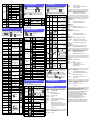
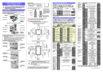
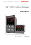
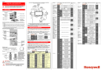
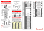
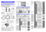
1 /16 - 1/8 - 1/4 DIN PROCESS CONTROLLERS CONCISE PRODUCT MANUAL (59300-7) CAUTION: Installation should be only performed by technically competent personnel. It is the responsibility of the installing engineer to ensure that the configuration is safe. Local regulations regarding electrical installation & safety must be observed - e.g. US National Electrical Code (NEC) and/or Canadian Electrical Code. Impairment of protection will occur if the product is used in a manner not specified by the manufacturer. Panel-Mounting For n multiple instruments mounted side-by-side, cut-out 1 1 1 A is 48n-4mm ( /16 & /8 Din) or 96n-4mm ( /4 Din) 1. INSTALLATION Some installation details vary between the three model sizes covered by this manual (refer to section 10). These differences have been clearly shown. 1 Installing Option Modules: /16 Din Size Instruments CPU PCB Option Module 3 Option Module 2 Tolerance +0.5, -0.0mm 2. Hold front bezel firmly (without pressing on display area), and re-fit mounting clamp. Push clamp forward, using a tool if necessary, until gasket is compressed and instrument held firmly in position. Ratchets Gasket Option Module A A Mounting Panel Mounting Struts Option Module 1 B 1. Insert instrument into the panel cut-out. Instrument Housing CAUTION: For an effective IP66 seal against dust and moisture, ensure gasket is well compressed against the panel, with the 4 tongues located in the same ratchet slot. 1 Rear Terminal Wiring: /16 Din Size Instruments USE COPPER CONDUCTORS (EXCEPT FOR T/C INPUT) PSU PCB 1 Single Strand wire gauge: Max 1.2mm (18SWG) 1 Select mode is used to access the configuration and operation menu functions. It can be accessed at any time by holding down and pressing . In select mode, press or to choose the required mode, press to enter. An unlock code is required to prevent unauthorised entry to Configuration, & Setup modes. Press or to enter the unlock code, then press to proceed. Mode Operator Set Up Configuration Product Info Tailor settings to the application Configure the instrument for use Check manufacturing information 1 Rear Terminal Wiring: /8 & /4 Din Size Instruments 1 Lower Upper Adjustment range & Description Display Display Option Slot A Connectors PL5 & PL6 Option Slot 3 Connector PL4B 1 Option Module Connectors: /8 & /4 Din Size Instruments Option Slot B Connectors PL2A, PL2B & PL2C Option Slot 2 Connector PL4A These diagrams show all possible option combinations. The actual connections required depends on the exact model and options fitted. Option Slot 3 Connector PL4B CAUTION: Check information label on housing for correct operating voltage before connecting supply to Power Input Fuse: 100 – 240V ac – 1amp anti-surge 24/48V ac/dc – 315mA anti-surge Note: At first power-up the message is displayed, as described in section 7 of this manual. Access to other menus is denied until configuration mode is completed L: 0.0 - 537.7 ºC L: 32.0 - 999.9 ºF PtRh20% vs 40%: 32 - 3362 ºF C: 0 - 2320 ºC N: 0 - 1399 ºC Pt100: –199 - 800 ºC C: 32 - 4208 ºF N: 32 - 2551 ºF J: –200 - 1200 ºC R: 0 - 1759 ºC . Pt100: –128.8 - 537.7 ºC J: –328 - 2192 ºF R: 32 - 3198 ºF . Pt100: –199.9 - 999.9 ºF . J: –128.8 - 537.7 ºC S: 0 - 1762 ºC 0 - 20 mA DC . J: –199.9 - 999.9 ºF S: 32 - 3204 ºF 4 - 20 mA DC K: –240 - 1373 ºC T: –240 - 400 ºC 0 - 50 mV DC K: –400 - 2503 ºF T: –400 - 752 ºF .10 - 50 mV DC Pt100: –328 - 1472 ºF . K: –128.8 - 537.7 ºC . T: –128.8 - 400.0 ºC 0 - 5 V DC . K: –199.9 - 999.9 ºF . T: –199.9 - 752.0 ºF 1 - 5 V DC L: 0 - 762 ºC PtRh20% vs. 40%: 0 - 1850 ºC Output 1 Usage Default Value . L: 32 - 1403 ºF Option Module Connectors: /16 Din Size Instruments . PSU PCB 1 Alarm Inhibit None B: 211 - 3315 ºF Option Module 1 Option Slot A Connectors PL5 & PL6 B: 100 - 1824 ºC Option Module 3 Option Slot 1 Connectors PL7 & PL8 Normal operation Dev. Alarm 2 Value* Alarm 2 Hysteresis* Loop Alarm Loop Alarm Time* 3. CONFIGURATION MODE Option Module 2 1 Default Unlock Codes None First select Configuration mode from Select mode (refer to section 2). Press to scroll through the parameters, then press or to set the required value. Press to accept the change, otherwise parameter will revert to previous value. To exit from Configuration mode, hold down and press , to return to Select mode. Note: Parameters displayed depends on how instrument has been configured. Refer to user guide (available from your supplier) for further details. Parameters marked * are repeated in Setup Mode. Option Module A Option Slot 2 Connector PL4A Description Auto-Tuning Invoke Pre-Tune or Self-Tune Note: The instrument will always return automatically to Operator mode if there is no key activity for 2 minutes. Option Module B To access modules 1, A or B, first detach the PSU and CPU boards from the front by lifting first the upper, and then lower mounting struts. Gently separate the boards. a. Plug the required option modules into the correct connectors, as shown below. b. Locate the module tongues in the corresponding slot on the opposite board. c. Hold the main boards together while relocating back on the mounting struts. d. Replace the instrument by aligning the CPU and PSU boards with their guides in the housing, then slowly push the instrument back into position. Note: Option modules are automatically detected at power up. Lower Display Input See following table for possible codes Range/Type Code Input Type & Code Input Type & Code Input Type & Range Range Range Mounting Struts Option Slot 1 Connectors PL7 & PL8 Upper Display Parameter Installing Option Modules: /8 & /4 Din Size Instruments CPU PCB Parameter 2. SELECT MODE The mounting panel must be rigid, and may be up to 6.0mm (0.25inch) thick. Cut-out sizes are: Cut-Out Dim A Cut-Out Dim B 1 1 1 /16 & /8 Din = 45mm /16 Din = 45mm 1 1 1 /4 Din = 92mm /8 & /4 Din = 92mm 0 - 10 V DC 2 - 10 V DC Note: Decimal point shown in table indicates temperature resolution of 0.1° Parameter Lower Upper Adjustment range & Description Default Display Display Value Scale Range Lower Limit +100 Range max Scale Range to Range Maximum (Lin=1000) Upper Limit Range Minimum to Range min Scale Range Scale Range Upper Limit -100 (Linear=0) Lower Limit 0=XXXX, 1=XXX.X, 2=XX.XX, 3=X.XXX Decimal point 1 (non-temperature ranges only) position Primary only Control Type Primary & Secondary (e.g. heat & cool) Reverse Acting Primary Output Control Action Direct Acting Process High Alarm Process Low Alarm Alarm 1Type Deviation Alarm Band Alarm No alarm High Alarm 1 Range Max Range Minimum to Range Maximum in value* display units Low Alarm 1 Range Min value* Band Alarm 1 1 LSD to span from setpoint in display units value* Dev. Alarm 1 +/- Span from setpoint in display units value* Alarm 1 1 LSD to full span in display units Hysteresis* Alarm 2 Type* High Alarm 2 Range Max value* Options as for alarm 1 Low Alarm 2 Range Min value* Band Alarm 2 value* Linear Output 1 Range Retransmit Output 1 Scale maximum Retransmit Output 1 Scale minimum Output 2 Usage Linear Output 2 Range Retransmit Output 2 Scale maximum Retransmit Output 2 Scale minimum Output 3 Usage Linear Output 3 Range Retransmit Output 3 Scale maximum Retransmit Output 3 Scale minimum Display Strategy Serial Communications Protocol Lower Upper Adjustment range & Description Display Display Options as for alarm 1 (disabled) or (enabled) 1 sec to 99 mins. 59secs . No alarms Inhibited Alarm 1 inhibited Alarm 2 inhibited Alarm 1 and alarm 2 inhibited Primary Power Secondary Power Alarm 1, Direct Alarm 1, Reverse Alarm 2, Direct Alarm 2, Reverse Loop Alarm, Direct Loop Alarm, Reverse Logical Alarm 1 OR 2, Direct Logical Alarm 1 OR 2, Reverse Logical Alarm 1 AND 2, Direct Logical Alarm 1 AND 2, Reverse Retransmit SP Output Retransmit PV Output 0 to 5 V DC output 0 to 10 V DC output 2 to 10 V DC output 0 to 20 mA DC output 4 to 20 mA DC output -1999 to 9999 (display value at which output will be maximum) -1999 to 9999 (display value at which output will be minimum) As for output 1 As for output 1 -1999 to 9999 (display value at which output will be maximum) -1999 to 9999 (display value at which output will be minimum) As for output 1 As for output 1 -1999 to 9999 (display value at which output will be maximum) -1999 to 9999 (display value at which output will be minimum) , , , , or (refer to section 8) ASCII Modbus with no parity Modbus with Even Parity Modbus with Odd Parity 1.2 kbps . . Comms Write Digital Input 1 Usage Digital Input 2 Usage Serial . Communications . Bit Rate . Comms Address Default Value Range max Range min Sec or Al2 Range max Range min Range max Range min 2.4 kbps 4.8 kbps . 9.6 kbps 19.2 kbps 1 to 255 (Modbus), 1 to 99 (ASCII) Read/Write Read only Setpoint 1 / Setpoint 2 select* Automatic / Manual select Setpoint 1 / Setpoint 2 select* Automatic / Manual select Remote / Local setpoint select Note: has priority over if both are configured for the same usage. If or = the remote setpoint input is disabled. Continued on next page… Parameter Lower Upper Adjustment range & Description Display Display 0 to 20 mA DC input 4 to 20 mA DC input 0 to 10 V DC input 2 to 10 V DC input Remote Setpoint 0 to 5 V DC input Input Range 1 to 5 V DC input Default Value 0 to 100mV DC input Available on full RSP Potentiometer (Slot B) only (2K minimum) RSP Upper Limit -1999 to 9999 Range max RSP Lower Limit -1999 to 9999 Range min Constrained within Scale Range Upper & RSP Offset Scale Range Lower limits Configuration 0 to 9999 Lock Code 4. SETUP MODE Note: Configuration must be completed before adjusting Setup parameters. First select Setup mode from Select mode (refer to section 2). The MAN LED will light while in Setup mode. Press to scroll through the parameters, then press or to set the required value. To exit from Setup mode, hold down and press to return to Select mode. Note: Parameters displayed depends on how instrument has been configured. Parameter Lower Display Input Filter Time Constant Process Variable Offset Primary Power Secondary Power Primary Proportional Band Secondary Proportional Band Automatic Reset (Integral Time) Rate (Derivative Time) Overlap/Deadband Manual Reset (Bias) Primary ON/OFF Differential Secondary ON/OFF Diff. Prim. & Sec. ON/OFF Differential Setpoint Upper Limit Setpoint Lower limit Primary Output Power Limit Output 1 Cycle Time Upper Display Adjustment Range & Description OFF or 0.5 to 100.0 secs Span of controller Current power levels (read only) 0.0% (ON/OFF) and 0.5% to 999.9% of input span . 00 secs to 99 mins 59 secs -20 to +20% of Primary and Secondary Proportional Band 0%(-100% if dual control) to 100% Current Setpoint to Range max R/max Range min to Current Setpoint R/min 0% to 100% of full power 0.5, 1, 2, 4, 8, 16, 32, 64, 128, 256 or 512 secs. Deviation Alarm 1 Value Band Alarm 1 value Alarm 1 Hysteresis High Alarm 2 value Low Alarm 2 value 1 LSD to full span in display units Range Minimum to Range Maximum Deviation Alarm 2 Value Band Alarm 2 value 1 LSD to full span in display units 1 LSD to full span in display units Range Minimum to Range Maximum Span from SP in display units 1 LSD to span from setpoint Span from SP in display units 1 LSD to span from setpoint . (disabled) or (enabled) R/max R/min R/max R/min . 1 to 9999 units/hour or Off (blank) Off Scale range upper to lower limits. (when dual or remote setpoint options are used, is replaced by & or Scale Range Minimum Local Setpoint Value Setpoint 1 Value Setpoint 2 Value or before the legend indicates the currently active SP) 0 to 9999 Lower Display Pre-Tune Self-Tune Upper Display Tune Lock 0 to 9999 * Note: Automatic tuning will not engage if either proportional band = 0. Also, Pre-tune will not engage if setpoint is ramping, or the PV is less than 5% of input span from the setpoint. 6. PRODUCT INFORMATION MODE First select Product information mode from Select mode (refer to section 2). Press to view each parameter. To exit from Product Information mode, hold down and press to return to Select mode. Note: These parameters are all read only. Parameter Lower Display Upper Display Description Universal input No option fitted Input type Option 1 module type fitted Option 2 module type fitted Relay output SSR drive output Triac output Linear DC voltage / current output As Option 1 Option 3 module type fitted Auxiliary Option A module type fitted No option fitted Relay output SSR drive output Linear DC voltage / current output Transmitter power supply No option fitted RS485 communications Digital Input* Remote Setpoint Input (basic)* Firmware type No option fitted Remote Setpoint Input (full) and Digital Input 2* Value displayed is firmware type number Firmware issue Value displayed is firmware issue number Auxiliary Option B module type fitted Product Revision Level Date of manufacture Serial number 1 Value displayed is Product Revision level Manufacturing date code (mmyy) First four digits of serial number Serial number 2 Middle four digits of serial number Serial number 3 Last four digits of serial number 7. MESSAGES & ERROR INDICATIONS Parameter Upper Lower Display Display Description Configuration & Setup required. This screen is seen at first turn on, or if hardware Instrument configuration has been changed. Press to parameters are in enter the Configuration Mode, next press default conditions or to enter the unlock code number, then press to proceed Process variable input > 5% over-range Input Over Range Normal Input Under Process variable input > 5% under-range Normal Range Input Sensor Break detected in process variable input Normal Break sensor or wiring RSP Over Range Normal ** RSP input over-range ** also seen RSP Under Normal ** RSP input under-range wherever RSP Range value would be Break detected in RSP displayed RSP Break Normal ** input signal Option 1 module fault Option 1 Error Option A Error Option B Error Lower Display Strategy and Description Display When Visible Active PV and target value of selected SP 1 & 2 (initial screen) Local Setpoints are adjustable in PV Value SP Strategy 2 Value Actual PV and actual value of selected SP 3 & 6 (initial screen) (e.g. ramping SP value). Read only PV Value SP Value Process variable only (Blank) 4 (initial screen) PV Value Read only Active SP Target value of selected setpoint (Blank) 5 (initial screen) only. Read only Value 1, 3, 4, 5 & 6 if digital Target value of SP Adjustable except in Strategy 6 SP Value input is not and RSP not fitted Target value of SP1 Digital input = . SP1 Value Adjustable except in Strategy 6 lit if active SP = SP1 Target value of SP2 Digital input = . SP2 Value Adjustable except in Strategy 6 lit if active SP = SP2 RSP fitted. Target value of local setpoint Local SP Adjustable except in Strategy 6 or lit if the Value active SP = RSP fitted. Target value of remote setpoint Remote SP Read only or lit if the Value active SP = Selects local/remote active setpoint = local SP, = remote SP RSP is fitted, digital = selection via digital input , input is not and (if configured). Note: selecting or is enabled in or will override digital input, Setup mode active SP indication changes to Adjustable except in Strategy 6 Actual SP Actual (ramping) value of is not blank selected SP. Read only Value SP ramping rate, in units per hour enabled in Ramp Rate Adjustable except in Strategy 6 Setup mode When one or more Alarm 2 active alarms are active. Active Alarm Alarm 1 active Status ALM indicator Loop Alarm active will also flash Option 2 module fault Option 3 module fault Option A module fault or RSP in both A & B Option B module fault Sensor Break Detection: Isolation: 4 to 20 mA, 2 to 10V and 1 to 5V ranges only. Control outputs turn off if RSP is the active SP. Slot A - Basic isolation, Slot B - Reinforced safety isolation from other inputs and outputs. DIGITAL INPUTS Volt-free(or TTL): Isolation: Open(2 to 24VDC) = SP1, Local SP or Auto Mode, Closed(<0.8VDC) = SP2, Remote SP or Manual Mode. Reinforced safety isolation from inputs and other outputs. OUTPUTS Relay Contact Type & Rating: Lifetime: Isolation: SSR Driver Drive Capability: Isolation: Single pole double throw (SPDT); 2A resistive at 120/240VAC. >500,000 operations at rated voltage/current. Basic Isolation from universal input and SSR outputs. SSR drive voltage >10V into 500 min. Not isolated from universal input or other SSR driver outputs. Triac Operating Voltage: Current Rating: Isolation: DC Types / Ranges Load Resistance: 20 to 280Vrms (47 to 63Hz). 0.01 to 1A (full cycle rms on-state @ 25°C); derates linearly above 40°C to 0.5A @ 80°C. Reinforced safety isolation from inputs and other outputs. 0 to 20mA, 4 to 20mA, 0 to 5V, 0 to 10V or 2 to 10V Resolution: Current Output 500 max, Voltage Output 500 min. 8 bits in 250mS (10 bits in 1s typical, >10 bits in >1s typical). Isolation: Reinforced safety isolation from inputs and other outputs. Transmitter PSU Power Rating: Isolation: 20 to 28V DC (24V nominal) into 910 minimum resistance. Reinforced safety isolation from inputs and other outputs. SERIAL COMMUNICATIONS Physical: RS485, at 1200, 2400, 4800, 9600 or 19200 bps. Protocols: Selectable between Modbus and West ASCII. Isolation: Reinforced safety isolation from all inputs and outputs. OPERATING CONDITIONS (FOR INDOOR USE) Ambient Temperature: Relative Humidity: Altitude 0°C to 55°C (Operating), –20°C to 80°C (Storage). 20% to 95% non-condensing. <2000m Supply Voltage and 100 to 240VAC 10%, 50/60Hz, 7.5VA Power: (for mains powered versions), or 20 to 48VAC 50/60Hz 7.5VA or 22 to 65VDC 5W (for low voltage versions). Manual Control ENVIRONMENTAL If is set to in Setup mode, manual control can be selected/de-selected by pressing the key in Operator mode, or by changing the status of a digital input if or have been configured for in Configuration mode. While in Manual Control mode, the indicator will flash and the lower display will show xxx (where xxx is the current manual power level). Switching to/from manual mode is via Bumpless Transfer. Press or to set the required output power. Caution: Manual power level is not restricted by the power limit. Standards: CE, UL, ULC, CSA EMI: Complies with EN61326 (Susceptibility & Emissions). Safety Considerations: Complies with EN61010-1, UL61010-1 & CSA 22.2 No 1010.1 92 Pollution Degree 2, Installation Category II. Front to IP66 when correctly mounted – refer to section 1. Rear of panel to IP20. 9. SERIAL COMMUNICATIONS These messages indicate that an error has occurred or there is a problem with the process variable signal or its wiring. Caution: Do not continue with the process until the issue is resolved. Option 2 Error Option 3 Error Upper Display Default Value or . Indication remains if automatic tuning cannot be used at this time* Parameter Low Alarm 1 value Setup Lock Code 0.1% to 10.0% of input span centered about the setpoint. (Entered as a percentage of span) Setpoint Value . Output 3 Cycle Time High Alarm 1 value Auto Pre-tune Auto/manual Control selection Setpoint Select shown in Operator Mode Setpoint ramp adjustment shown in Operator Mode SP Ramp Rate Value N/A This mode is entered at power on, or accessed from Select mode (see section 2). Note: All Configuration mode and Setup mode parameters must be set as required before starting normal operations. Press to scroll through the parameters, then press or to set the required value. Note: All Operator Mode parameters in Display strategy 6 are read only (see in configuration mode), they can only be adjusted via Setup mode. First select Automatic tuning mode from Select mode (refer to section 2). Press to scroll through the modes, then press or to set the required value. To exit from Automatic tuning mode, hold down and press , to return to Select mode. Pre-tune is a single-shot routine and is thus self-disengaging when complete. If in Setup mode = , Pre-tune will attempt to run at every power up*. Refer to the full user guide (available from your supplier) for details on controller tuning. . Loop Alarm Time . 1 sec to 99 mins 59 secs and OFF Output 2 Cycle Time Alarm 2 Hysteresis Default Value 8. OPERATOR MODE 5. AUTOMATIC TUNING MODE Refer to the full user guide (available from your supplier) for details. 10. SPECIFICATIONS UNIVERSAL INPUT Thermocouple Calibration: 0.1% of full range, 1LSD (1°C for Thermocouple CJC). BS4937, NBS125 & IEC584. PT100 Calibration: 0.1% of full range, 1LSD. BS1904 & DIN43760 (0.00385 / /°C). DC Calibration: 0.1% of full range, 1LSD. 4 per second. Sampling Rate: Impedance: Sensor Break Detection: Isolation: >10M resistive, except DC mA (5) and V (47k ). Thermocouple, RTD, 4 to 20 mA, 2 to 10V and 1 to 5V ranges only. Control outputs turn off. Isolated from all outputs (except SSR driver). Universal input must not be connected to operator accessible circuits if relay outputs are connected to a hazardous voltage source. Supplementary insulation or input grounding would then be required. REMOTE SETPOINT INPUT Accuracy: Sampling Rate: 0.25% of input range 1 LSD. 4 per second. Panel Sealing: PHYSICAL Front Bezel Size: 1 Weight: 0.21kg maximum. 1 /16 Din = 48 x 48mm, /8 Din = 96 x 48mm, /4 Din = 96 x 96mm. 1 1 1 Depth Behind Panel: /16 Din = 110mm, , /8 & /4 Din = 100mm. 1 SUPPLEMENTARY INFORMATION FOR CSA -Compliance shall not be impaired when fitted to the final installation. -Designed to offer a minimum of Basic Insulation only. -The body responsible for the installation is to ensure that supplementary insulation suitable for Installation Category II is achieved when fully installed. -To avoid possible hazards, accessible conductive parts of the final installation should be protectively earthed in accordance with EN6010 for Class 1 Equipment. -Output wiring should be within a Protectively Earthed cabinet. -Sensor sheaths should be bonded to protective earth or not be accessible. -Live parts should not be accessible without the use of a tool. -When fitted to the final installation, an IEC/CSA APPROVED disconnecting device should be used to disconnect both LINE and NEUTRAL conductors simultaneously. Do not to position the equipment so that it is difficult to operate the disconnecting device.