1
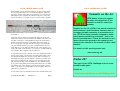
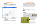
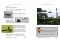
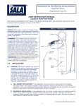
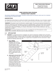
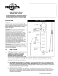
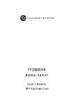
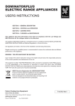
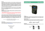
www.sotabeams.co.uk
www.sotabeams.co.uk
WWW.SOTABEAMS.CO.UK
© SOTA Beams 2007
SB5 Issue A
Page 16
© SOTA Beams 2007
SB5 Issue A
Page 1
www.sotabeams.co.uk
www.sotabeams.co.uk
Introduction
Thank you for purchasing the SB5 Portable Yagi System. This
beam has been designed with lightweight portable radio operating
in mind. Every component and aspect of its design has been carefully considered to make it as easy
TIP—Throughout these inas possible to assemble, carry, and
structions you will see boxes use. It has been designed by Richwith tips and notes. Tips are
ard Newstead, G3CWI, who has
things that you may wish to
over 25 years of portable radio
do to enhance the performoperating experience in places as
ance of your system.
wild as Antarctica! The art of effective portable operating relies on
good preparation so read these instructions carefully and practice
with your new antenna at home before you take it into the wilds.
Preparing the system for use
Before using your SB5 there are a few simple tasks to undertake:
1)
Assembly of the antenna elements
2)
Assembly and adjustment of the guying system
3)
Construction of the feeder system
4)
Learning how to erect the system.
You may have many years of experience or perhaps you are new
to radio but either way, we suggest that you read and follow these
instructions before trying to use our SB5.
Tools
You will need the following simple tools:
•
•
•
•
Tape measure (a metal measuring tape is best)
Ruler
Craft knife
Soldering iron and solder
© SOTA Beams 2007
SB5 Issue A
Page 2
Operating tips
“Location, location, location” is the cry of estate agents but it is
equally applicable to radio amateurs. Getting the best out of your
beam demands choice of the right location. Height makes a big
difference on 2 metres so aim to get to a local high point.
Most antennas work best if the ground falls away in the direction
you want to make contacts in. Operating from the middle of a high
plateau is therefore often discouraging while operating nearer the
edge will improve things a lot.
Mount the antenna horizontal for SSB (elements parallel to the
ground) and vertical for FM. FM sounds nicer but far greater range
will be achieved with SSB!
Be considerate when operating portable. Don’t put guys across
paths and generally avoid getting in people’s way. Don’t make lots
of noise on the hills either—people often come to hilltops to enjoy
some peace and quiet so please don’t give them a bad impression
of our hobby.
Guarantee
These beams have been designed for portable operation. They are
not suitable for permanent home-station use. We guarantee these
beams to be free from manufacturing defect for 12 months from the
date of purchase. If you have any problems or questions about the
beam, please contact us by e-mail ([email protected]) or
by post to: SOTA Beams, 89 Victoria Road, Macclesfield, Cheshire, SK10 3JA. You can also contact us by phone on 01625-425700
during normal working hours.
The SOTA name and logo are used with express permission of the SOTA management team. The SOTA programme is a not-for-profit Amateur Radio organisation
which is wholly independent of SOTA Beams and ECS Ltd.
© SOTA Beams 2007
SB5 Issue A
Page 15
www.sotabeams.co.uk
www.sotabeams.co.uk
Help!
Additional photographs of the construction techniques and the
beam in use are at http://www.sotabeams.co.uk/sb5-help.htm This
page will also show any updated construction information.
•
•
•
•
Safety goggles
Wire cutters
Hot air gun (paint stripper gun)
Pencil
1) Assembly of the Antenna Elements1
A SOTAbeams user group is at:
http://groups.yahoo.com/group/sotabeams/
Still stuck?
If you have any problems or questions about the beam, please contact us by e-mail ([email protected]) or by post to: SOTA
Beams, 89 Victoria Road, Macclesfield, Cheshire, SK10 3JA. You
can also contact us by phone on +44 (0)1625-425700 during normal UK working hours.
Warnings
Never use your antenna on a hilltop when
there are thunderstorms nearby or forecast.
Always ensure that your antenna is erected
in such a way that it does not represent a
hazard to yourself or others.
Remove the soft plastic cap from the longer of the plastic tubes
and tip out the antenna elements. Cup
TIP—The caps slide
them in your hand to stop them falling on
on easier if you moisthe ground! There are six rods which have
ten the ends of the rods
been precision cut to work first time. Find
with saliva (yuk!).
the packet of red soft plastic endcaps. Put
an endcap on one end of each of the rods
so that all the rods have one endcap on. The two shortest rods
(each about 48cm long) form the driven element of the Yagi and
are now complete; put them to one side. You now have four long
elements left.
Find the length of 4mm heat-shrink sleeving and,
using a craft knife, cut a piece 1cm long. Make
sure that you cut squarely across the tubing. Next
cut three pieces 2cm long and one 3cm long.
Keep the remaining sleeving—it will be used
later.
Never erect an antenna near to power lines.
Select the longest element (just over 1m long).
From the end without the endcap, measure
527mm and mark the rod with a pencil. Make a second mark
552mm from the same end (you should now have
two marks 25mm apart). Slide a 2cm piece of heatshrink sleeving down the element so that the end of
the sleeving is at the mark nearest the endcap (see
photograph). Note that the photo shows the marks
much closer to the endcap than they will be on your
element. Using the hot air gun, heat the sleeving so
© SOTA Beams 2007
© SOTA Beams 2007
SB5 Issue A
1 The antenna elements are the aluminium rods!
SB5 Issue A
Page 14
Page 3
www.sotabeams.co.uk
www.sotabeams.co.uk
that it shrinks onto the element and the epoxy glue coating inside
the sleeving melts. Before it cools make sure that the end of the
sleeving is exactly at the mark on the element—you can move it a
little while it’s hot (careful!). Get another 2cm piece of sleeving
and do the same process again (see photo below). This completes
Summits on the Air
the reflector.
!
Select the shortest element (just under 1m long). From the end
without the endcap, measure 474mm and mark the rod with a pencil. Slide a 1cm piece of heatshrink sleeving down the element so
that the end of the sleeving is at the mark nearest the endcap as
above. Using the hot air gun, heat the sleeving so that it shrinks
onto the element and the epoxy glue coating inside the sleeving
melts. Before it cools make sure that the end of the sleeving is exactly at the mark on the element—you can move it a little while it’s
hot (careful!). This completes the front director.
You should now have two element of the same length (just under a
metre). Select either one. From the end without the endcap, measure 483mm and mark the rod with a pencil. Slide a 2cm piece of
heatshrink sleeving down the element so that the end of the sleeving is at the mark nearest the endcap as above. Using the hot air
gun, heat the sleeving so that it shrinks onto the element and the
epoxy glue coating inside the sleeving melts. Before it cools make
sure that the end of the sleeving is exactly at the mark on the element—you can move it a little while it’s hot (careful!). This completes the second director.
You now have just one element left. From the end without the end© SOTA Beams 2007
SB5 Issue A
Page 4
!
"
"
#
$
%
Under 18?
&
"
'
%
http://www.sotabeams.co.uk/Challenge.htm
© SOTA Beams 2007
SB5 Issue A
Page 13
www.sotabeams.co.uk
www.sotabeams.co.uk
Technical Stuff
The SB5 is based on a design by Martin DK7ZB. It is used with his
permission—thanks Martin. The exact dimensions are slightly different due to the different production techniques and materials we
have used. The polar diagram is shown below. This is the Free
Space diagram.
cap, measure 487mm and mark the rod with a pencil. Slide a 3cm
piece of heatshrink sleeving down the element so that the end of the
sleeving is at the mark nearest the endcap as above. Using the hot
air gun, heat the sleeving so that it shrinks onto the element and the
epoxy glue coating inside the sleeving melts. Before it cools make
sure that the end of the sleeving is exactly at the mark on the element—you can move it a little while it’s hot (careful!). This completes the third director.
The elements can now be returned to the boom tube for safe keeping.
2) Assembling the Guying System
You will need a tape-measure, a pair of scissors, a box
of matches.
The VSWR should be below 1.7:1 across the 2m band. A stacking
kit with various contest enhancements is available at
www.sotabeams.co.uk .
The recommended maximum power rating for the standard version
(with crocodile clips) is 25W. The contest kit is rated at 400W.
© SOTA Beams 2007
SB5 Issue A
Page 12
Locate the hank of guying cord and cut into four equal lengths. In
the components pack you will find a plastic ring
about 35mm in diameter and 25mm long. This
TIP—A Bowline
is the guying ring. Tie each one of the four
would be a good knot
length of cord to the guying ring as illustrated.
for the guying ring and
Tie a loop about 5cm long in the other ends of
a Figure of Eight for
the cords. Seal the ends of the nylon cord with a the loops.
lighted match
being careful not to set the cord
alight or to drop burning nylon on
yourself or anything else. Once all
four guylines are complete, fold
and loosely knot them to keep
them tidy.
© SOTA Beams 2007
We have used a 4-guy system for
this aerial is it gives greater stability and control when erecting and
taking down the system. This is
SB5 important,
Issue A especially when aPage 5
www.sotabeams.co.uk
www.sotabeams.co.uk
breeze springs up!
Preparing the feedline
Need: ruler, craft knife, wire strippers, soldering iron, solder, small vice, heat gun.
The SB5 is supplied with feeder cable that
is fitted with a BNC plug. Take the unterminated end and feed 80cm up through the
choke sleeve as illustrated.
Wind
eight turns of cable on the
sleeve (tightly) and pass the
unterminated end down
through the hole in the other
end of the choke sleeve. You
should now have about 10cm
of co-ax protruding from the choke sleeve.
Strip exactly 25mm of the outer insulation and make a pigtail (not a pig’s ear)
of the braid as shown . Strip 5mm of
insulation of the centre core and tin 5mm
of the ends of the braid and core. Cut
two pieces of heat-shrink sleeving
(supplied) 15mm long. Slide these over
the centre core and braid as far down and
away from the tinned area as possible
(see photo).
Put one crocodile clip in a vice and lightly tin the end. Put the
braid into the clip, bend over the cable support tabs and solder.
Solder quickly to avoid excess heat shrinking the sleeving. Slide
© SOTA Beams 2007
SB5 Issue A
Page 6
TIP—The SB5 has an exceptionally clean radiation
pattern so it’s handy to know where it is pointing. Put
a piece of insulating tape around the top of the lower
mast section and mark it A,B...H at 45 degree intervals. When you have chosen your operating position
(on the ground near the aerial), use a compass to
make a table of aerial directions e.g. C=East,
D=South East, E= South etc. This will help you to
point your aerial accurately. Leave the tape on and make a new
table each time you use the SB5. Don’t forget a compass!
© SOTA Beams 2007
SB5 Issue A
Page 11
www.sotabeams.co.uk
www.sotabeams.co.uk
You will have noticed that the heatshrink sleeving is used to identify the elements—if they are inserted in the wrong positions your
beam will not work! Once the beam is assembled, lay it flat on the
ground out of the way.
the sleeving over the crocodile clip as far as possible and shrink
using a heat gun. Repeat the process with the centre core. To waterproof the open top of the co-ax, use a thin clear glue such as
Bostik.
Run the feeder along the length of the mast such that the choke is at
the top of the mast. Loosely clip the feeder to the mast with two
cable ties about 1m and 1.5m down from the top. Slide the beam
onto the mast using centre pair of brackets. Mount in with the elements horizontal for use on SSB and vertical for use on SSB.
Arranging the Guys for Travelling
Clip the crocodile clips onto the elements as shown in the photograph. Make sure that they get a good “bite”. Tighten the cable
clips such that there is no strain on the crocodile clips from the
feeder running down the mast. This is VERY important!
Once the beam is on the mast and the feeder is attached, lift the
mast to vertical and peg. You are now ready to operate.
In very windy conditions you may be reluctant to erect the SB5. In
that case, use the Stubby. The Stubby is a 3 element close spaced
Yagi and is made with just the short boom section. As a director us
the element with the 1 cm sleeving—this gives the best VSWR.
The Stubby has its own set of brackets.
Test have shown that the SB5 and Stubby have a reasonable
VSWR on 70cm. Performance is not guaranteed on this band and
the radiation pattern is very odd. However, you might make a few
contacts.
TIP—When you pack the beam up you
may like to put the rings and endcaps
on the elements to keep them safe. The
elements will fit in the boom with them
on if you don'
t want to use the built in storage
© SOTA Beams 2007
SB5 Issue A
Page 10
Guys can be a problem on hilltops. They can easily get in a tangle
unless you handle them with care. We recommend that you double
up each guy then loosely tie it with an overhand knot. Finally slide
an elastic band over it to keep it together. Do this with each guy so
that you have four bundles. It is well worth taking the time to do
this properly when you pack up on a hilltop too.
TIP—The plastic
screw-caps
can easily
Preparing the Pole for use
be broken when not
For VHF only use, it is often easiest to remove the
fixed onto the pole.
three thinnest sections of the 7m telescopic pole.
Handle them with care!
Do this by unscrewing the plastic endcap and sliding the three thinnest sections out at the base of the
pole. Replace the screw cap.
TIP—tie the yellow cap to one of
the mounting
brackets. That
way it cannot get lost.
And finally
In the pack you will note a yellow cap. This fits over
the end of the nylon boom connection part and creates a little storage compartment. Put 4 of the plastic
element endcaps and four of the small O rings in
there. The cap has a long pull-tab allowing you to remove it with
gloves on.
Locate the three reusable cable ties (also specially selected to be
usuable with gloves on!) and store them with the elements inside
the long boom section.
You are now ready for your first expedition. However, we advise
that your first expedition is to your garden or a local park on a fine
day as you can then practice the techniques that will allow you to
use your SB5 successfully under all conditions.
© SOTA Beams 2007
SB5 Issue A
Page 7
www.sotabeams.co.uk
www.sotabeams.co.uk
TIP—Use the cable
ties to attach the long
Getting on the Air
part of the boom to
the pole for easy carrying On arrival at your operating location choose a flat area of
ground about 5m by 5m. Check to see which direction the
wind is coming from. Extend the pole. Start by pulling out the smallest
section first. Lock each section by pulling firmly
at the same time as twisting the section. This
makes the sections lock in place using friction.
Lay the pole on the ground with the tip facing
into the wind. Slide he guying ring down the
mast as far as it will go. Peg out two side guys
and a back guy. Erect the pole and peg the final
guy. Adjust the guys so that they are all at 90
degrees to each other and are all well pegged and
not too tight.
Slip off one guy so that the pole can be lowered
into the wind. The next stage is to assemble the
beam.
cap and put the O rings and small element caps to one side.
Connect the long boom section to the short boom section and slide
the element with the 3cm heatshrink marker (D3) through to hold
the boom together (you may find that you do not need an O ring to
hold this element in place). The two short element sections are the
driven element. These must be inserted either side into the holes in
the nylon bolt. Locate the element with two heatshrink markers
(Reflector) and insert through the boom at the end closest to the
driven element. Only push it about 2cm through, then slide an O
ring over the end and slide it all the way through s that the O ring
remains next to the boom and will stop the element falling out; this
is quicker than sliding the O rings on after fully inserting the elements. Insert the remaining elements as shown in the diagram.
TIP—Always insert
pegs so that the guy-line
comes off at right-angles
to the peg .
Remove the soft rubber endcap and take the elements and cable ties out of the long boom section. Keep the endcap
safe as you will need it when you pack up again. Remove the yellow
TIP—The friction lock is quite reliable in most cases but
may fail in windy conditions, causing one or more sections to collapse. This is likely to damage the aerial and
pole. To avoid this happening, you may like to make a
safety lock system. this is done by drilling a small hole
through both sides of the pole just above the joint. In use a
solid rod can be inserted through the holes which will stop
any collapse happening. We recommend a 3mm diameter
rod and a 3.1mm diameter hole. The best way to drill the hole is to do
one side at a time and then rotate the pole to drill the other side.
© SOTA Beams 2007
SB5 Issue A
Page 8
© SOTA Beams 2007
SB5 Issue A
Page 9