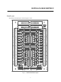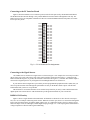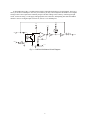
1
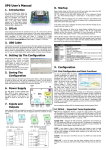
DOP8/16/24 Optoisolated Digital Input Board User's Manual ® Real Time Devices USA, Inc. Accessing the Analog World® Publication No. DOP24-9742 DOP8/16/24 User's Manual ® REAL TIME DEVICES USA Post Office Box 906 State College, Pennsylvania16804 Phone: (814) 234-8087 FAX: (814) 234-5218 Published by Real Time Devices USA, Inc. P.O. Box 906 State College, PA 16804 Copyright © 1997 by Real Time Devices, Inc. All rights reserved Printed in U.S.A. Rev. A 9742 INTRODUCTION The DOP8, DOP16, and DOP24 optoisolated digital input boards provide 8, 16, or 24 optoisolated input channels for digital signal sensing and switch monitoring applications. These boards can drive 8, 16, or 24 digital input lines and are pin-for-pin compatible with DIO24 and DIO48 boards that can be used to directly drive opto-22 racks. The DOP8/16/24 features: • • • • • 8, 16 or 24 optoisolated digital input channels, LED indicators to monitor input logic status, Input buffered with voltage comparators, Adjustable threshold level, On-board screw terminals for easy wiring. What Comes With Your Board You receive the following items in your DOP8/16/24 package: • DOP8, DOP16, or DOP24 mechanical relay output board • User’s manual If any item is missing or damaged, please call Real Time Devices’ Customer Service Department at (814) 234-8087. If you require service outside the U.S., contact your local distributor. In addition to the items included in your DOP8/16/DOP24 package, Real Time Devices offers a full line of board accessories. Key accessories for the DOP include the TB50 terminal board and XB50 prototype/terminal board which can be connected to the daisy chain connector for prototype development and easy signal access, and the DWK-1 and DWK-2 discrete wire kits for connecting 40-pin interface boards to the 50-pin DOP board. Using This Manual This manual is intended to help you get your new board running quickly, while also providing enough detail about the board and its functions so that you can enjoy maximum use of its features even in the most complex applications. We assume that you already have an understanding of data acquisition principles and that you can provide the software necessary to control the DOP board. When You Need Help This documentation package should provide enough information for you to achieve your desired results. If you have any problems using this board, contact our Technical Support Department, (814) 234-8087, during regular business hours, eastern standard time or eastern daylight time, or send a FAX requesting assistance to (814) 234 5218. When sending a FAX request, please include your company’s name and address, your name, your telephone number, and a brief description of the problem. 1 2 DOP8/16/24 DESCRIPTION Board Layout The DOP8/16/24 board layout is shown in Figure 1 below. Fig. 1 — DOP8/16/24 Board Layout 3 Connecting to the PC Interface Board Figure 2 shows the DOP24’s P1 I/O connector pinout, with all of the pins used by the DOP24 board labeled. The DOP8 board uses DOUT0 through 7 only, and the DOP16 board uses DOUT0 through DOUT15 only. The DOP board is pin-for-pin compatible with Real Time Devices’ DIO24 and DIO48 boards with pinouts for connection to opto-22 systems. DOUT16 1 2 N.C. DOUT17 3 4 DIGITAL GND DOUT18 5 6 DIGITAL GND DOUT19 7 8 DIGITAL GND DOUT20 9 10 DIGITAL GND DOUT21 11 1 2 DIGITAL GND DOUT22 13 14 DIGITAL GND DOUT23 15 16 DIGITAL GND DOUT8 17 18 DIGITAL GND DOUT9 19 20 DIGITAL GND DOUT10 21 22 DIGITAL GND DOUT11 23 24 DIGITAL GND DOUT12 25 26 DIGITAL GND DOUT13 27 28 DIGITAL GND DOUT14 29 30 DIGITAL GND DOUT15 31 32 DIGITAL GND DOUT0 33 34 DIGITAL GND DOUT1 35 36 DIGITAL GND DOUT2 37 38 DIGITAL GND DOUT3 39 40 DIGITAL GND DOUT4 41 42 DIGITAL GND DOUT5 43 44 DIGITAL GND DOUT6 45 46 DIGITAL GND DOUT7 47 48 DIGITAL GND +5 VOLTS 49 50 DIGITAL GND Fig. 2 — P1 I/O Connector Pin Assignments Connecting to the Signal Sources The DOP8/16/24 is connected to a signal source as shown in Figure 3. For example, the circuit may be used to detect closure of a switch. The positive side of the switch would be connected to the positive (+) terminal on the DOP board and the negative, or ground, side would be connected to the negative (–) terminal. The channel output is connected to a digital input line on your digital I/O board through DOP8/16/24 connector P1. If your interface board’s digital I/O is provided by an 8255 programmable peripheral interface (PPI), then you must set up the lines that routed through the optoisolation circuitry on the DOP as mode 0 inputs. The interface board manual tells you how to set up the PPI. TB1 and TB2 are 25-terminal miniature screw terminal strips which let you easily connect and disconnect the digital inputs from external devices. TB1 and TB2 also provide ground terminals for your convenience. DOP8/16/24 Circuitry Figure 3 shows a single channel on the DOP board. All channels are identical. To show how the circuit operates, let’s use our example of detecting switch closure. When the switch is open, there is no current flow through the input circuit, the DOP LED is off, and the digital output is low, or 0. When the switch is closed, a current is generated in the input circuit, the LED lights, and the digital output goes high, or to 1. The input signal is buffered with a voltage comparator to allow flexible signal conditioning. 4 A threshold trimpot, TR1, is included on the board to adjust the threshold level for all channels. The level is factory set at about 1 milliampere. In a noisy environment, you may want to adjust the threshold level to a higher setting to achieve the required noise immunity and prevent false readings. This is done by connecting an input circuit, such as one using a 5-volt supply and appropriate series resistance, and adjusting TR1 until the LED for channel 1 turns on at a higher input current level, such as 5 or 10 milliamperes. +5 V +5 V +5 V IN + OUT + IN +5 V THRESHOLD Fig. 3 — DOP8/16/24 Channel Circuit Diagram 5 6 APPENDIX A DOP8/16/24 SPECIFICATIONS A-1 A-2 DOP8/16/24 Characteristics Typical @ 25° C Input Circuitry Number of channels ..................................................................................... 8, 16 or 24 Type of optoisolator ............................................................................................... 4N25 Input current, per channel .......................................................................... 80 mA, max Buffering .......................................................................................... voltage comparator Threshold voltage/current ..................................................... 1.5 volts/1 mA, adjustable Maximum input voltage .................................................................................. 1500 Vdc Current Requirements +5 volts (inputs = 0) ............................................................................................. 85 mA Power Requirements +5 volts ..................................................................................................... From PC bus Connectors Two 50-pin box headers Screw Terminals TB1 and TB2 - 25-terminal 22-12 AWG wire Size 6.875"L x 5.0"W (175mm x 127mm) A-3 A-4 APPENDIX B DOP24 PINOUT B-1 B-2 DOP24 Pinout: DOUT16 1 2 N.C. DOUT17 3 4 DIGITAL GND DOUT18 5 6 DIGITAL GND DOUT19 7 8 DIGITAL GND DOUT20 9 10 DIGITAL GND DOUT21 11 1 2 DIGITAL GND DOUT22 13 14 DIGITAL GND DOUT23 15 16 DIGITAL GND DOUT8 17 18 DIGITAL GND DOUT9 19 20 DIGITAL GND DOUT10 2 1 2 2 DIGITAL GND DOUT11 23 24 DIGITAL GND DOUT12 2 5 2 6 DIGITAL GND DOUT13 2 7 2 8 DIGITAL GND DOUT14 2 9 3 0 DIGITAL GND DOUT15 3 1 3 2 DIGITAL GND DOUT0 33 34 DIGITAL GND DOUT1 35 36 DIGITAL GND DOUT2 37 38 DIGITAL GND DOUT3 39 40 DIGITAL GND DOUT4 41 42 DIGITAL GND DOUT5 43 44 DIGITAL GND DOUT6 45 46 DIGITAL GND DOUT7 47 48 DIGITAL GND +5 VOLTS 49 50 DIGITAL GND B-3 B-4 APPENDIX C WARRANTY C-1 C-2 LIMITED WARRANTY Real Time Devices, Inc. warrants the hardware and software products it manufactures and produces to be free from defects in materials and workmanship for one year following the date of shipment from REAL TIME DEVICES. This warranty is limited to the original purchaser of product and is not transferable. During the one year warranty period, REAL TIME DEVICES will repair or replace, at its option, any defective products or parts at no additional charge, provided that the product is returned, shipping prepaid, to REAL TIME DEVICES. All replaced parts and products become the property of REAL TIME DEVICES. Before returning any product for repair, customers are required to contact the factory for an RMA number. THIS LIMITED WARRANTY DOES NOT EXTEND TO ANY PRODUCTS WHICH HAVE BEEN DAMAGED AS A RESULT OF ACCIDENT, MISUSE, ABUSE (such as: use of incorrect input voltages, improper or insufficient ventilation, failure to follow the operating instructions that are provided by REAL TIME DEVICES, “acts of God” or other contingencies beyond the control of REAL TIME DEVICES), OR AS A RESULT OF SERVICE OR MODIFICATION BY ANYONE OTHER THAN REAL TIME DEVICES. EXCEPT AS EXPRESSLY SET FORTH ABOVE, NO OTHER WARRANTIES ARE EXPRESSED OR IMPLIED, INCLUDING, BUT NOT LIMITED TO, ANY IMPLIED WARRANTIES OF MERCHANTABILITY AND FITNESS FOR A PARTICULAR PURPOSE, AND REAL TIME DEVICES EXPRESSLY DISCLAIMS ALL WARRANTIES NOT STATED HEREIN. ALL IMPLIED WARRANTIES, INCLUDING IMPLIED WARRANTIES FOR MECHANTABILITY AND FITNESS FOR A PARTICULAR PURPOSE, ARE LIMITED TO THE DURATION OF THIS WARRANTY. IN THE EVENT THE PRODUCT IS NOT FREE FROM DEFECTS AS WARRANTED ABOVE, THE PURCHASER’S SOLE REMEDY SHALL BE REPAIR OR REPLACEMENT AS PROVIDED ABOVE. UNDER NO CIRCUMSTANCES WILL REAL TIME DEVICES BE LIABLE TO THE PURCHASER OR ANY USER FOR ANY DAMAGES, INCLUDING ANY INCIDENTAL OR CONSEQUENTIAL DAMAGES, EXPENSES, LOST PROFITS, LOST SAVINGS, OR OTHER DAMAGES ARISING OUT OF THE USE OR INABILITY TO USE THE PRODUCT. SOME STATES DO NOT ALLOW THE EXCLUSION OR LIMITATION OF INCIDENTAL OR CONSEQUENTIAL DAMAGES FOR CONSUMER PRODUCTS, AND SOME STATES DO NOT ALLOW LIMITATIONS ON HOW LONG AN IMPLIED WARRANTY LASTS, SO THE ABOVE LIMITATIONS OR EXCLUSIONS MAY NOT APPLY TO YOU. THIS WARRANTY GIVES YOU SPECIFIC LEGAL RIGHTS, AND YOU MAY ALSO HAVE OTHER RIGHTS WHICH VARY FROM STATE TO STATE. C-3 C-4