1
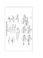
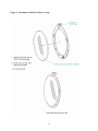
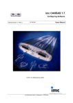
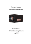
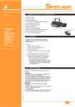
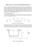
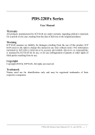
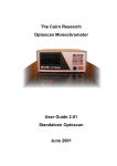
Lycian Stage Lighting
M2
Modular Follow Spotlight System
Instruction Manual
Lycian Stage Lighting
PO Box D, Kings Highway, Sugar Loaf NY 10981 USA
Tel: 845 469 2285
Fax: 845 469 5355
www.lycian.com
LYCIAN M2
Modular follow spotlight system
Introduction
Congratulations! You have chosen Lycian's revolutionary new modular follow spotlight
system. This innovative system is comprised of modules that can be easily assembled into various
configurations allowing a design to fit specific applications or to reconfigure as the requirements
change.
The modular system is based on the ability to change the followspot to have either a short, medium
or long throw lens; to change between a 1200W or 2500W HMI light source with either an
electronic or magnetic ballast. This concept gives maximum flexibility to designers, rental houses
and customers for their application and budget. For ease of use, the followspot can conveniently be
set up to be operated from either side.
The M2 followspot employs an optical system with two modes of operation, changeable by
introducing the “Flip Flop” lens:
Fixed focus provides more efficiency and produces a high intensity beam. Good for head
and waist shots at shorter throws and a brighter beam capability at longer throws.
Variable focus provides a zoom effect and gives a wider beam capability and the ability to
adjust gobo patterns to fit the target.
Modular System Components
In the M2 system, the Power Chassis module is the core of the system and all other modules are
mounted to it. Each module is described below to give a better understanding of the concept behind
the modular approach.
Power Chassis #2010
The power chassis is the base upon which the spotlight is built. The lamphouse and gate assembly
mount on top of the chassis. The lens assembly slides on from the front. The electronic power
supply inserts from below and mounts inside. When using a magnetic power supply, an adaptor
plate with a Veam connector mounts inside and connects to the outboard power supply. On/Off
controls and a lamp timer are visible on this module.
2
Gate assembly #2085
The gate assembly is the module that controls beam shape, intensity, softness, focus, and special
colors. The components are described below starting at the lamp:
Iris - controls the diameter of the beam. It is manufactured of a special nichrome alloy for
high temperature operation and is further protected by a unique variable heat shield.
Square Shutter - A shutter with two sets of blades which allow independent horizontal and
vertical chopping. When operated together they give a square beam.
Gobo Slot - Accepts our #802 gobo holder and size “B” gobos.
“Flip-Flop” Lens - With the lens flipped out of the beam (focus is now controlled by the
lens control handle on the front mounted lens system) the narrowest, and brightest beam
field is produced. With the lens flopped into the light path, the control handle on the front
changes the focal length. By loosening the green knob and sliding the flip-flop lens back
and forth, various optical focal lengths are obtained. As the focal length is increased, the
brightness is increased.
Four Lever Color Boom - Included for dichroic or other glass filters. The 3.75” diameter
glass filters are mounted on small aluminum rings for easy and rapid changing even during
a performance. These filters are useful for color correction, blacklight, or when using
various colors for long periods of times. The boom arms operate independently.
Fader - Adjusts beam intensity.
Variable Frost Filter - Frost filters are introduced into the light beam to provide varying
degrees of frost.
The gate module is mounted on top of the power chassis and can be installed for either left or righthand operation. A door covers the unused opening and has basic operating instructions on the
inside. When the module is installed for right sided operation, all the controls in the down position
ensure a clear and maximum light path, i.e. no filters, iris wide open.
Lamphouses
1200W lamphouse #2012
The 1200W lamphouse uses a short 1200 Watt double ended HMI type lamp manufactured by
several lamp vendors and uses precision condenser optics to produce a flat and very clean beam.
The lamphouse contains a no-tool lamp holder, condensing lens, quiet cooling fans, reflector, high
voltage igniter, and safety interlock switches. The top door hinges open for lamp changes and
cleaning.
3
2500W lamphouse #2025
The 2500W lamphouse uses a short 2500 Watt double ended HMI lamp manufactured by Osram
and uses precision condenser optics to produce a flat and very clean beam. A long HMI type lamp
is not useable. The lamphouse contains a no-tool lamp holder, condensing lens, quiet cooling
blower, reflector, high voltage igniter, and safety interlock switches. The top door hinges open for
lamp changes and cleaning. Changing of the lamp requires releasing both lamp lever locks located
on the top of the lamp socket cooling fins. Rotating backward the rear fin assemblies, the lamp can
be lowered into the pre-aligned socket. Rotating the rear fin assemblies forward and engaging the
two cam lock latches will conclude the installation.
Lenses
All three lens assemblies have yoke mounts that can be rotated forward or backwards to
accommodate the difference in weight of the 2500W and 1200W lamphouses. The entire lens
system slides onto the power chassis module and is retained with four captive screws. A sliding
counterbalance underneath the medium and long lenses adjusts the balance to your preference. On
all three lenses a clip is provided on which to hang your favorite communication microphone.
Short lens system #2020
The short lens system is designed for short throw applications to approximately 75' or other various
uses. Using a single 6" clear optical grade lens, the short lens system can produce a beam spread
from 0.62° to 11.8°. A single top mounted knob adjusts the focus in both the fixed focus
application and the beam spread in variable focus applications. A friction adjustment screw, located
in the lens trolley and visible when the 2020 is removed from the spotlight changes the feel of the
lens knob. The type of focus is selected on the gate module. Containing no color boom, the lens
system depends on the gate module dichroic color boom, or the front mounted color boom 2002 or
a front mounted color scroller from other manufacturers. (Adaptor plates are available from
Lycian).
Medium lens system #2040
The medium lens system is designed for medium throw application, from 75' to 150', or other
various uses. It uses a single 9" clear optical grade glass lens mounted on a trombone slide control
with a twist-lock brake. This control adjusts the focus in fixed focus application and beam spread in
a variable focus application. Focus type is selected on the gate module. The lens can be controlled
from ether side of the unit. The medium lens system can produce a beam spread from 0.31° to 7.6°.
A six-color automatic self-canceling color boom is included.
Long lens system #2060
The long lens system is designed for long throw application, from 100’ to 300', or other various
uses. It uses a single 11" clear optical grade glass lens mounted on a trombone slide control with a
twist-lock brake. This control adjusts the focus in fixed focus application and the beam spread in
variable focus applications. Focus type is selected on the gate module. The lens can be controlled
from ether side of the unit. The long lens system can produce a beam spread from 0.28° to 5.6°. A
six-color automatic color boom is included.
4
Power Sources
Electronic power supply 1200/2500 Watt #935
The 1200W/2500W intelligent electronic power supply senses which lamphouse (1200 or 2500
watt) is mounted and operates the lamp accordingly, detecting the input voltage and adjusting
accordingly.
The #935 power supply will operate a 1200 watt lamp at any line voltage from 100V to 250V,
50/60 Hz, or a 2500 watt lamp from 200V to 250V, 50/60 Hz. A red LED mounted next to the
power switch indicates when either lamp is missing, or is out of manufacturers recommended
operating range. Old lamps may trigger this indicator. The power supply mounts from beneath into
the #2010 power chassis. A 12' power cable is included. This power supply is of the flicker free
type with active power factor correction.
Magnetic power supply adaptor chassis #2076
The power supply adaptor chassis mounts from beneath into the #2010 power chassis. The male
VEAM connector allows the use of 1200W and 2500W magnetic power supplies with the M2
system. Several safety features prevent lamps from being damaged if the incorrect power supply is
connected to the desired lamphouse.
1200W 120 Volt 60Hz magnetic power supply #927
The 927 power supply is Lycian's standard 1200W magnetic power supply. Constructed with an
extruded aluminum chassis it is designed to sit on the floor next to the spotlight connecting to the
spotlight head with a short cable and VEAM connector. An additional cable connects to the power
source. The 927 operates a 1200W HMI type lamp on 120 volts 60Hz only.
1200W 100V to 240V 50/60 Hz magnetic power supply #927/UT
The 972/UT is identical to the 927 but has input voltage and frequency taps so it may operate from
100V to 240V at 50Hz or 60 Hz.
2500W 200V to 240V 50/60Hz magnetic power supply #939
This power supply allows the followspot to operate from 200V to 240V AC at 50Hz or 60Hz by
adjustment of tappings. It is constructed with an extruded aluminum chassis and is designed to sit
on the floor next to the spotlight and connect to the spotlight head with a short cable and VEAM
connector. An additional 12ft long cable connects to the power source.
Yoke and Base
Yoke assembly #2001
The yoke assembly mounts on either a 1315, 1315/4 base or an appropriate male stud. Pan and tilt
friction locks are included. The yoke can be mounted on the follow spot head and remain there
when the unit is placed in a road box. The 3/8-16 bolt must be tight to prevent the spotlight from
shaking on the base or stud.
5
3-legged folding base #1315
The 1315 is a folding 3-legged base. Loosening the captive screws will allow the legs to fold to a
compact size. A sliding pole will give additional height of 13". This base will hold either the short
or medium lens configuration.
4-legged folding base #1315/4
The 1315/4 is a 4-legged version of the 1315 and is appropriate for the long lens configuration, but
can be used with any lens or lamphouse combination.
Color Changers
In addition to the dichroic color changer in the gate module, the medium and long lens assemblies
each have easily removable color changers for use with gels. They are also reversible with the
blank panel for left sided operation of the followspot.
Outboard color boom for short throw lens assembly #2002
The outboard front mounted color boom is intended for the short lens configuration only and
includes six self-canceling color arms. It can be installed for left or right side operation. It can also
be removed completely if a very short followspot is needed. The dichroic color changer in the gate
module can still be use for colors.
Building the spotlight:
The spotlight requires seven parts. See Fig 1.
1) Power Chassis: 2010
2) Gate Assembly: 2085
3) Lamphouse: 2012 (1200W) OR 2025 (2500W)
4) Power Supply:
935 (Electronic 1200W/2500W) OR
927 1200W magnetic, with 2076 magnetic adapter OR
939 2500W magnetic, with 2076 magnetic adapter.
5) Lens Assembly: 2020 Short or 2040 Medium or 2060 Long
6) Yoke Assembly: 2001
7) Base: - 1315 or 1315-4 (Not required if truss mounted)
6
7
Assembling the spotlight
The followspot will be fully assembled in the configuration ordered. The modular system allows
for interchangeability of alternative assemblies. The following description assumes all modules are
separated.
To assemble the spotlight, place the power chassis on a table with the large opening facing
upwards. Using the six 10-32 screws, lock washers and flat washers provided, insert the power
supply or power supply adaptor plate and secure with the screws. Roll the chassis over so that the
power supply is on the bottom and the fan to your right.
Next mount the lamphouse. With the lens to the right, plug the short cable with the AMP connector
into the receptacle on the power supply as seen thru the hole on the top of the chassis. The
lamphouse can now be lowered on top of the chassis slightly to the rear of its final position. Engage
the two pins into the holes on the front of the lamphouse and slide it forward. Tighten the two
captive screws at the rear.
Lower the gate assembly into the gate housing with the iris next to the lamphouse. Engage the holes
in the bottom rail of the gate assembly with the two pins on the chassis. Tighten the four captive
screws. Note that the gate may be mounted for either left or right hand operation. A door is
provided to cover the unused opening and allows access for cleaning and changing dichroics.
The required lens system can now be slid onto the power chassis from the front and the four captive
screws tightened. The yoke mounts should be rotated forward or backwards to suit the choice of
lamphouse. If using the lighter 1200 watt lamp, loosen the 3 nuts holding each yoke mount and
rotate them completely forward towards the front of the spotlight and tighten. If using the heavier
2500 watt lamphouse, rotate the mounts completely to the rear and tighten the nuts. It is important
for the yoke mounts to be rotated to the ends of their travel for the spotlight to balance.
Setting the spotlight on the base
Set up the base by rotating each of the legs, until the captive screw engages. Tighten the screws.
With the base wheels down, mount the yoke on top of the notched pipe. Rotate the yoke so that the
pin located in the yoke socket engages the notch, then tighten the 3/8-16 bolt. Neglecting to tighten
this bolt will allow the spotlight to shake. Loosen the two silver captive knobs on top of the yoke
and rotate the keeper plates out of the way. The spotlight head now can be lowered onto the yoke.
Note: mount the spotlight head with the tilt brake on the intended operator side, (the yoke can be
mounted for left or right operation). Rotate the keeper plates over the bearings and tighten the
knobs. Stabilizing jacks are provided on each leg, which should be fully tightened during operation
to avoid a shaky fixture. These jacks are to lift the light off of its wheels and are not intended for
leveling.
8
Balancing the spotlight
The spotlight can be "balanced to taste" by sliding the balancing weight located under the lens
assembly. (Long and medium lenses only) Please note: when changing from one lamphouse to
another the yoke mount must be rotated, forward (away from the lamp) for the 1200 watt unit and
to the rear (towards the lamp) for the 2500 watt unit. To rotate the yoke mount, first loosen the 3
nuts securing the mount to the chassis, rotate it to the end of its travel, and retighten the nuts. Both
yoke mounts must be locked in the same direction for the spotlight to balance. A 7/16” socket with
¼” drive will make this task easier.
Lamping
1200W Lamphouse.
The catch on the back of the lamphouse has a thin release bar in the center which needs to be
depressed before the catch can be opened. With the lid open, stand to the right of the fixture with
the lamphouse on your left.
To install the 1200W lamp, first remove the two lamp ferrules from the lamp. Rotate the left brass
contact so that the slot in the left insulator is unobstructed. Holding the lamp’s left contact,(your
choice) insert the right lamp contact into the hole in the right lamp insulator. The left side should
fall into the slot. Now swing the left brass contact back into position and slide the lamp over to the
left and into the hole in the contact. Rotate the lamp so that the small pip on the glass envelope is
pointing vertically up. Screw the left ferrule on and tighten. Install the ring lug onto the right end of
the threaded lamp stud and install the right ferrule. Hold the right lamp contact in your fingers
while doing so.
The glass envelope should be cleaned using alcohol wipes to remove grease and acids which will
deteriorate the glass surface leading to early lamp failure.
Periodically, it is recommended that the tightness of the ferrules be checked.
2500W Lamphouse.
The catch on the back of the lamphouse has a thin release bar in the center which needs to be
depressed so that catch can be opened. With the lid open, stand to the right of the fixture with the
lamphouse on your left.
The combined heatsink and lamp contacts in the lamphouse need to be opened to allow for lamp
installation. A lever on the top of each contact should be lifted up and forward and unhooked from
the main contact. The back half of the contact/heatsink can now be pulled backwards revealing the
intended lamp locating hole. The spring-loaded reflector should be held back. Lower the lamp into
the lamp contacts keeping the lamp centered. Locating pins help with this.
9
Push both contacts closed but do not tighten. Rotate the lamp so that the small pip on the glass
envelope is vertically up. Close and tighten each latch to lock. There should be tension as they lock.
Allow the reflector to return to its correct location, parallel to the lamphouse lens.
The glass envelope should be cleaned using alcohol wipes to remove dirt, grease and acids which
will deteriorate the glass surface leading to early lamp failure.
Iris care
The nickel-chrome iris has been heat treated and oxidized to give a dark green appearance. The iris
is then lubricated using a micro-fine molybdenum powder which ensures smooth operation at
extended temperatures. Periodic “dusting” of the iris, using a small make-up brush will ensure
continued operation.
Microfine powdered moly lubricant Item # 10065K21 available from McMaster is most suitable.
Available from Lycian; part #196.
A multiblade heatshield covers the majority of the iris at all apertures and reduces the heat absorbed
by the iris to extend its lifetime. The aluminum heatshield may be periodically polished with
chrome cleaner to ensure continued operation.
DO NOT USE an oil or silicone based lubricant on the iris as it will burn off very quickly emitting
noxious fumes. The oil will also become tacky and cause the iris to jam.
Gelling
Remove the color boomerang by unscrewing the two captive screws and lifting out and up. Color
gels can now be fitted between the color frame plates and fastened with brass clips or small cable
ties (by others).
Dichroic filters
Dichroic filters may be installed onto the dichroic color changer arms located in the gate module.
The dichroics are glued to removable aluminum rings with small beads of silicone adhesive.
The dichroics should be 3-3/8” (86-92mm) diameter. Additional dichroic rings Part #1301 are
available from a Lycian distributor.
See Fig 2.
10
Figure 2. Attachment of dichroic filters to rings.
11
Lamps
The 1200W is an HMI short arc double-ended lamp with ferrules. The mounting length is 135mm.
The following manufacturers currently provide such lamps:
Osram HMI 1200W/S
Ushio UMI-1200/HB
Koto HMI 1200HB
The 2500W is an HMI short arc double-ended lamp. The overall length is 210mm (8¼”)
The following manufacturers currently provide such lamps:
Osram HMI 2500W/S
Electrical requirements
The requirement for the modular followspot depends on the lamphouse chosen and the intended
ballast.
The 2500W lamphouse will operate from 200V to 240V AC 50/60Hz only. The electronic ballast,
will draw constant power from the supply and therefore will draw a higher current at 200V than at
240V. At 200V the current draw will be about 18A and the fixture should therefore be connected to
a 30A service. The circuit breaker on the power supply is rated at 25A. The magnetic 2500W
ballast will require the same 30A service.
The 1200W lamphouse will operate from any voltage from 100V to 240V AC 50/60Hz. It will
draw 16A at 100V and 8A at 240V. A 20A service will be suitable for this lamphouse, whether it
be with the electronic or magnetic ballast.
Both the electronic and magnetic power supplies are single phase only.
The green wire must be connected to ground or earth.
The black wire may be connected to a hot or live line or one phase of a three-phase system.
The white wire may be connected to a neutral line or another phase of a three phase system.
12
Feeder cables
This section is included as Lycian is frequently asked for recommendations on cable sizes for
hooking up our followspots. We also want to ensure that the followspots are correctly wired
particularly in temporary installations such as arenas and touring shows.
For the 2500W lamphouse fixture, the minimum operating voltage measured at the followspot line
cord, (not the distribution panel at the other end of the building) is 200V AC 50/60Hz.
The 2500W M2 electronic ballast draws 18A at 200V AC. Each fixture should be fed from its
own 30A circuit breaker.
Depending on the extension or feeder cables used, the table below shows the required cable gauge
to achieve the minimum recommended 200V at the followspot, with various input voltages at the
distribution panel. Input voltages of 220V -240V can follow the 208V column thereby giving
minimum dissipation in the cables.
Maximum cable length versus gauge for M2 2500W at given panel voltages
to achieve 200V minimum at the followspot.
Wire Gauge
14 Ga
12 Ga
10 Ga
8 Ga
6 Ga
----------------- Panel Voltage -------------------208V
206V
204V
70ft
50ft
35ft
110ft
80ft
55ft
175ft
130ft
80ft
280ft
200ft
140ft
450ft
330ft
220ft
The heavier the cable used the less power is dissipated in the cables. For example 12Ga feeder
cable at 18A drops 8V (from 208V to 200V). Power dissipation in the cable is 8V X 18A = 144W.
13
Operation of the spotlight
Recommend spotlight book, available from Lycian.
Getting The Most From Your Followspot - An Operator’s Handbook, by Bert Morris.
Maintenance
The heart of any followspot is the optical system. Periodic cleaning of the lenses and lamp will
keep the fixture operating at its brightest. The exterior surfaces of the fixture can be cleaned with
soap and water on a damp cloth or similar. It is not necessary to oil any of the lens trombone rods
but cleaning them with a dry cloth will prevent them from becoming stiff or binding. If the
followspot is used in a dusty environment, blowing out the fans and air intake holes with canned air
or an air hose occasionally is recommended.
Be sure to keep the air intake areas of the power supply clear to ensure maximum cooling to the
power supply and lamp.
The lenses may be cleaned with alcohol or lens cleaning solution, 3M wipes also have been found
to clean the lenses without leaving any residue. Coffee filters are also suggested as they are lint
free.
Electrical and thermal safety features
There are several safety interlocks and voltage detection circuits in the followspot that will
shutdown the power supply in case of trouble.
•
Lamphouse lid safety switch. Prevents direct viewing of the lamp during operation. Shuts
off power to the lamp. No other indication.
•
Lamphouse over-temperature thermal switch. Shuts off power to the lamp if the interior
surface of the lamphouse exceeds a preset temperature. Failure of the fan or blower or
obstruction of the cooling airflow will cause this. A 10 minute cool down period will be
required.
•
Power supply over temperature switch. A restricted airflow through the power supply
will eventually cause it to shut down.
•
Input voltage incorrect. The 1200W lamphouse allows the power supply to operate from
100V to 240V. A voltage lower than 90V will cause the power supply to shutdown. A
2500W lamphouse will allow the power supply to operate from 200V to 240V. A voltage
lower than 180V at the fixture will shut down the power supply, also it will not start if
connected to 120V. A large voltage sag or insufficiently sized supply cable will cause the
14
power supply to shutdown. If voltage sags are unavoidable, a boost transformer may be
used with the electronic ballast. Alternatively a magnetic ballast may be used, however they
are not flicker free.
•
Lamp overvoltage. The 1200W and 2500W lamps have a manufacturer’s maximum
permissible operating voltage. When the lamp voltage exceeds 148V for a period of 30
seconds, the lamp power will be removed and cause the red LED to flash. This can be
caused by a very old or faulty lamp, or the lamp has not been installed correctly or is
missing.
•
Shorted lamp contacts. If the lamp contacts are shorted for more than 30 seconds the LED
will flash and the lamp power will be removed.
•
Lamp mis-strike. A mis-strike of the lamp i.e. it didn’t strike within 5 seconds during
ignition will cause the LED to flash after 30 seconds.
•
Arcing over. Arcing between the lamp contacts and chassis ground during ignition will
shutdown the power supply and the LED will flash after 30 seconds.
What’s wrong ?
Quality of light.
•
Lamp alignment. Ensure that the lamp is correctly located in the lampholders, and that the
center of the arc gap appears in the center of the lens and reflector. The filler pip on the
lamp glass envelope should be pointing up.
•
Incorrect focus. It is possible to cause the followspot to focus on items other than the iris
when adjusting the two lenses. At short distances the lamp envelope and even the electrodes
can be projected on a wall. Readjustment of the lenses will enable the iris to be viewed.
•
Objects partially in light path. If any of the color booms or the “flip-flop” lens are partially
inserted into the light path, it will cause an uneven beam. With all the gate assembly
controls set to the down position the light path should be maximum with no filters.
•
Broken lens. Although the lenses used are designed to withstand the high temperatures, it
may be possible for a lens to crack or shatter. Replacements are available from your Lycian
dealer.
•
Damaged iris. The iris is the most highly stressed component in the followspot. A non
circular beam will indicate defective leaves and the iris will then need to be replaced or
repaired. Return the iris to the Lycian factory for repair.
15
•
Lamp – melted, dirty, brown, milky. These are the signs of an old or well used lamp and
will continue to output less and less light. Dirt on the outside of the glass envelope will melt
into the glass causing a weak spot, The glass may also bulge out suggesting reduced
cooling.
•
Reflector misaligned. In the 2500W lamphouse the reflector is mounted on a swiveling plate
which allows for lamp installation. Check that the reflector sits parallel to the lens. The
1200W reflector is fixed and cannot be misaligned.
•
Lamphouse lens hazy, overheated. If the lamphouse lens looks to be milky or crazed in the
centre closest to the 2500W lamp, it has been thermally stressed. This may be due to
insufficient or reduced cooling. Operating the fixture below 200V AC causes the lamphouse
blower to run slower causing various cooling problems.
No light
• Is the LED flashing -Yes: No strike, no lamp, old lamp.
•
Is the LED flashing – No: Incorrect input voltage, safety switch open, overheated
lamphouse, no blower, restricted blower, only one fan in 1200W lamphouse.
•
No power at all. Check supply to followspot, is it plugged in?.
•
Fader closed.??!!
•
Power supply failure. Circuit breaker keeps tripping may indicate power supply failure.
Contact Lycian service dept. or your Lycian dealer.
Fixture shuts down.
•
After 4-5 minutes – thermal switch, no cooling, restricted cooling
•
After several hours. If LED flashing – lamp old, bad lamp connection.
•
After several hours. No flashing LED – Incorrect input voltage, power sag, brown out.
•
If in doubt, check the line voltage to the followspot at the followspot’s line cord whether it
be an attached plug or the breaker panel to which it is hard wired. If the followspot is on a
truss with hundreds of feet of extension cable, measure at the followspot line cord with it
running.
16
Accessories
Insert here a list of available accessories such as Sight Light, dichroics, spare dichroic rings, boost
transformers etc.
If there is anything you feel should be included in this manual that is not already covered, we
welcome your suggestions.
Lycian Stage Lighting,
21st August 2002
17