1
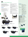
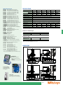
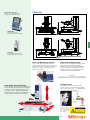
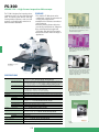
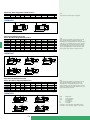
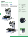
TM-500
SERIES 176 — Toolmaker's Microscopes
The Mitutoyo TM Series is a toolmaker's
microscope well suited for measuring
dimensions and angles of workpiece
features. It can also be used to check the
shape of screws and gears by attaching an
optional reticle. The compact body makes
it ideal for use on shop-floors with limited
space for measuring instruments.
FEATURES
•Angle measurement is performed easily by
turning the angle scale to align the crosshair reticle with the workpiece image.
•Illumination intensity can be adjusted.
Technical Data
Observation image:
Optical tube:
Erect image
Monocular (diopter adjustable)
Depression angle: 30˚
Reticle: 90˚ broken cross-hair
(176-126)
Angle reading:
Range: 360˚
Minimum reading: 6' (by vernier)
Eyepiece:
15X (176-116), View field dia.: 13mm
Optional: 10X, 20X
Objective:
2X (176-138),
Working distance: 67mm
Optional: 5X, 10X
Total magnification: 30X
Transmitted illumination
• Light source: Tungsten bulb (24V, 2W)
• Functions:
With green filter, Light intensity
adjustable
Surface illumination:
• Light source:
Tungsten bulb (24V, 2W)
• Functions:
Light intensity adjustable
Power supply:
100/110/120/220/240V AC, 50/60Hz
Mass:
13.5g (14.5kg: TM-510)
J
Angle reading
TM-505
TM-510
Refer to the TM-505/510 leaflet (E4158) for
more details.
J-16
176-115:
176-116:
176-117:
176-139:
176-137:
164-161:
10X eyepiece (view field dia.: 13mm)
15X projection lens set*
20X eyepiece (view field dia.: 10mm)
Objective, 5X (W.D.: 33mm, N.A.: 0.10)
Objective, 10X (W.D.: 14mm, N.A.: 0.14)
Digimatic micrometer head
(range: 50mm, reading: 0.001mm)
164-162: Digimatic micrometer head (range: 2”/50mm,
reading: .00005”/0.001mm)
152-390: Micrometer head for X-axis
(range: 50mm, reading: 0.005mm)
152-389: Micrometer head for Y-axis
(range: 50mm, reading: 0.005mm)
152-391: Micrometer head for X-axis
(range: 2”, reading: .0001")
152-392: Micrometer head for Y-axis
(range: 2”, reading: .0001")
611635-041:Rectangular gauge block (25mm)
611675-041:Rectangular gauge block (50mm)
611201-241:Rectangular gauge block (1")
611202-241:Rectangular gauge block (2")
383038:
Halogen bulb (24V, 2W)
176-204: Dial indicator attachment for Z-axis
measurement
965013:
SPC cable (2m) for Digimatic micrometer head
Fixture and Stage accessories
990561:
Workpiece clip (2pcs./set)
176-106: Rotary table for TM-505 (effective dia.: 66mm)
172-196: Rotary table for TM-510 (effective dia.:
100mm)
176-105: Swivel center support for TM-505
(max. workpiece dia.: 70mm)
172-197: Swivel center support for TM-510
(max. workpiece dia.: 80mm)
172-378: V-block with clamp
(max. workpiece dia.: 25mm)
176-107: Holder with clamp
SPECIFICATIONS
Model No.
Order No.
XY stage travel range
Measurement method
Floating function
XY stage table top size
Effective area of table
Max. workpiece height
Max. stage loading
Remarks
DIMENSIONS
Unit: mm
J
207.5
207.5
152
152
210
333
391
176-141:
176-142:
176-143:
176-144:
176-123:
176-124:
176-125:
176-120:
176-121:
176-122:
176-127:
176-128:
176-129:
176-130:
176-112:
Concentric circles
(up to ø4mm, 0.05mm increment)
Concentric circle (up to ø.2", .01" increment)
55˚ angle
60˚ angle
Metric screw threads (pitch = 0.25 - 1mm)
Metric screw threads (pitch = 1.25 - 2mm)
ISO metric screw threads
(pitch = 0.075 - 0.7mm)
ISO metric screw threads (pitch = 0.75 - 2mm)
ISO unified screw threads (80 - 28TPI)
ISO unified screw threads (24 - 14TPI)
ISO unified screw threads (13 - 10TPI)
Unified screw threads (80 - 28TPI)
Unified screw threads (24 - 14TPI)
Unified screw threads (13 - 10TPI)
Whitworth screw threads (60 - 26TPI)
Whitworth screw threads (24 - 18TPI)
Whitworth screw threads (16 - 11TPI)
NF screw threads (80 - 28TPI)
NF screw threads (24 - 14TPI)
NF screw threads (13 - 10TPI))
14.5˚ involute gear teeth (normal rack type)
20˚ involute gear teeth (normal rack type)
TM-510
176-812*
100 x 50mm
Micrometer head (optional)
—
240 x 152mm
154 x 96mm
107mm
5kg
—
*To denote your AC power cable add the following suffixes to the order No: A for UL/CSA, CED for CEE, CEE for BS,D for CEE, DC for CCC, E for BS, K for EK, No suffix is required for JIS/100V
Note) D and E are not compatible with CE
Illumination units
176-366: Fiber-optic ring light
176-203: Twin-bulb reflected illumination unit
176-344: Bifurcated fiber illuminator
Reticles
176-111:
176-135:
176-113:
176-114:
176-109:
176-110:
176-140:
TM-505
176-811*
50 x 50mm
Micrometer head (optional)
—
152 x 152mm
96 x 96mm
115mm
5kg
—
391
Optional Accessories
207.5
321.5
152
240
210
333
J-17
MF
SERIES 176 — Measuring Microscopes
The MF measuring microscopes'
expandability, such as when used in
combination with Mitutoyo's vision unit to
boost its performance or data management
on a PC, promises further improved
measuring efficiency.
FEATURES
•Observation with a clear and flare-less erect
image and a wide field of view
•Measuring accuracy that is the highest in its
class (and conforms to JIS B 7153)
•ML series, high-NA objectives that are
specially designed for the MF series (long
working distance type)
J
•Illumination unit (reflected/transmitted)
selectable from a high-intensity LED or
halogen bulb (required)
•Variable aperture diaphragm (reflected/
transmitted) allows observation measurement
while suppressing light diffraction
•Variety of standardized stages in sizes up to
400×200mm
•Quick-release mechanism useful for moving
the stage quickly when measuring workpieces
that are large in size or quantity
•Coarse/fine feed handles equipped as
standard on both sides allow precise focus
and observation measurement regardless of
handedness
•High-magnification eyepiece observation up
to 2000×
•Standard measuring microscope that has a
wide variety of optional accessories including
a Vision Unit and various digital CCD cameras
Technical Data
Observation image: Erect image
Optical tube (optional): Monocular or binocular tube
(depression: 25˚), Reticle projection
method, with TV mount, Optical path
ratio (eyepiece/TV mount: 50/50)
Eyepiece lens (optional):10X, 15X, 20X
Objective:
3X (375-037), W.D.: 72.5mm
Optional: 1X, 5X 10X, 20X, 50X, 100X
Transmitted illumination
• Light source: Halogen bulb (12V, 50W)
• Optical system: Telecentric illumination with adjustable
aperture diaphragms
• Functions:
Light intensity adjustable, Nonstepped brightness adjustment Surface
illumination
• Light source: Halogen bulb (12V, 150W)
• Optical system: Koehler illumination with adjustable
aperture diaphragms
• Functions:
Light intensity adjustable, Non-stepped
brightness adjustment Display unit:
• No. of axis: 2 axes (MF-A type) or 3 axes (MF-B type)
• Resolution:
0.001mm / 0.0005mm / 0.0001mm /
.0001" / .00005" / .00001"
• Functions:
Zero-setting, Direction switching, Data
output (via RS-232C interface)
Power supply:
100/110/120/220/240V AC, 50/60Hz
Mass:
65.5kg (505C, 1010C) / 69.5kg (2010C) /
130kg (2017C) / 138kg (3017C) /
144kg (4020C)
Optional Reticles for 3X Eyepiece
Using optional slide type nosepiece
with 2-lens mount (factory set
option)
12AAG838 (12AAG878):Cross-hair (7µm width)
12AAG836 (12AAG877):Cross-hair (5µm width)
12AAG873 (12AAG876):Cross-hair (3µm width)
12AAG839 (12AAG879):Cross-hair and 45˚ angle
12AAG840 (12AAG880):Broken cross-hair and 60˚ angle
12AAG841 (12AAG881):Zeiss type chart
12AAG842*:20mm scale (0.1mm reading)
12AAG843*:Concentric circle (ø1.2 - ø18mm)
12AAG844*:10mm scale (0.1mm reading)
12AAG845*:5mm scale (0.05mm reading)
12AAG846*:10x10mm section (1mm min.)
12AAG847*:Metric screw thread (P = 0.25-1.0)
12AAG848*:Metric screw thread (P = 1.25-2.0)
12AAG849*:Involute gear tooth (14.5˚), module = 0.1 - 1.0
12AAG850*:Involute gear tooth (20˚), module = 0.1 - 1.0
12AAG851*:Unified screw thread (80 - 28TPI)
12AAG852*:Unified screw thread (24 - 14TPI)
12AAG853*:Unified screw thread (13 - 10TPI)
12AAG854*:Concentric circle (ø.01" - ø.2")
( ): for MF-U models, *: MF/MF-U compatible
MF-B2017C
XY stage travel range: 200 x 170mm
(with optional binocular tube)
Selection of XY stage by travel range
505C: 50 x 50mm
1010C: 100 x 100mm
3017C: 300 x 170mm
2010B: 200 x 100mm
Reticle mount
(standard accessory)
for MF-U models
for MF models
90˚ chain line
Line width: 5µm
(standard accessory)
4020C: 400 x 200mm
Refer to the MF /MF-U leaflet (E4153) for more
details.
J-18
Optional Accessories
176-392: Monocular tube with 10X eyepiece
176-393: Binocular tube with 10X eyepiece set
378-856: 10X eyepiece set (view field dia.: 24mm)
378-857: 15X eyepiece set (view field dia.: 16mm)
378-858: 20X eyepiece set (view field dia.: 12mm)
375-043: Protractor eyepiece (10X)
176-313: Digital protractor eyepiece (10X)
375-036-2: 1X objective (W.D.: 61mm, N.A.: 0.03)
375-037-1: 3X objective (W.D.: 77mm, N.A.: 0.09)
375-034-1: 5X objective (W.D.: 61mm, N.A.: 0.13)
375-039: 10X objective (W.D.: 51mm, N.A.: 0.21)
375-051: 20X objective (W.D.: 20mm, N.A.: 0.42)
375-052: 50X objective (W.D.: 13mm, N.A.: 0.55)
375-053: 100X objective (W.D.: 6mm, N.A.: 0.7)
176-314-1: Slide type nosepiece (2-mount, parfocal)
176-314-2: Slide type nosepiece (2-mount, mag. adjusted)
12AAA643:ND2 color filter (transmitted / surface)
12AAA644:ND8 color filter (transmitted / surface)
12AAA645:GIF filter (transmitted / surface)
12AAA646:LB80 color filter (transmitted / surface)
375-054: 0.5X camera adapter (with C-mount adapter)
970441: C-mount adapter
513667: Halogen bulb (24V, 50W)
12BAB345:Halogen bulb (long life type, 24V, 50W)
176-308: Vibration damping stand
176-309: Mounting stand
375-056: Stage micrometer
12AAA165:Lens cleaning kit
12AAA846:Foot switch
Illumination units (Refer to page J-25.)
176-351-6: Oblique surface illumination unit
176-367-2: LED ring illuminator
176-343: Twin fiber-optics illuminator
176-366: Ring fiber-optics illuminator
12AAG806:GIF color filter (for fiber-optics illuminator)
12AAG807:LB80 color filter (for fiber-optics illuminator)
Fixture and Stage accessories (Refer to page J-15.)
176-107: Holder with clamp*
172-378: V-block with clamp*
(max. workpiece dia.: 25mm)
172-197: Swivel center support*
(max. workpiece dia.: 80mm)
176-305: Rotary stage with fine feed knob for
505C/1010C/2010C models
176-306: Rotary stage with fine feed knob for
2017C/3017C/4020C models
SPECIFICATIONS
Model No. (XY stage size)
505C
1010C
2010C
2017C
3017C
4020C
Order No.*
MF-A
176-661*
176-662*
176-663*
176-664*
176-665*
176-666*
MF-B
176-681*
176-682*
176-683*
176-684*
176-685*
176-686*
XY stage travel range
50 x 50mm
100 x 100mm 200 x 100mm 200 x 170mm 300 x 170mm 400 x 200mm
Z-axis travel range
150mm
150mm
150mm
220mm
220mm
220mm
Focusing method
Manual focusing (coarse focusing: 30mm/rev., fine focusing: 0.2mm/rev.)
Measurement method
Linear encoder (2-axis model: X / Y-axis, 3-axis model: X / Y / Z-axis)
Resolution (switchable)
0.001mm / 0.0005mm / 0.0001mm / .0001" / .00005" / .00001"
Measuring accuracy (at 20˚C) XY-aixs: (2.2+0.02L)µm, L = Measuring length (mm) when not loaded, JIS B 7153
Indication accuracy (at 20˚C) Z-axis: (5+0.04L)µm, L = Measuring length (mm)
Floating function
X and Y axes with Quick-release mechanism
XY stage top size
280 x 280mm 280 x 280mm 350 x 280mm 410 x 342mm 510 x 342mm 610 x 342mm
Effective glass size
180 x 180mm 180 x 180mm 250 x 150mm 270 x 240mm 370 x 240mm 440 x 240mm
Swiveling function
—
—
—
±5˚ (left)
±5˚ (left)
±3˚ (left)
Max. stage loading
10kg
10kg
10kg
20kg
20kg
15kg
Max. workpiece height
150mm
150mm
150mm
220mm
220mm
220mm
*The following suffixes to the order No. (e.g.: 176-661-10):
-10 for English User’s Manual 11 for Chinese user’s manual, No suffix is Japanese user’s manual
Selection of machine type
Machine type
Measurement system
J
MF-A
X and Y-axis (2-aixs type)
MF-B
X, Y and Z-axis (3-axis type)
LED
Halogen
176-345*
176-347*
Illumination Unit
Applicable
Illumination Unit
Order No.
*To denote your AC power cable add the following suffixes to the order No.: A for UL/CSA, C for Taiwan, D for CEE, DC for CCC, E for BS, K for EK, No suffix is required for JIS/100V
DIMENSIONS
90.5
261
327
249
Unit: mm
78
200
QM-Data200
2-D data processing unit
(Refer to page J-14 for more
details.)
12AAA807: Connecting cable set
114
360
234+50
413
667
79
330
*Fixture mount adapter (176-310) is required for 2010B models.
Fixture mount adapter (176-304) is required for 2017B/3017B/4020B models.
551
726.3+50
300+50
120.3
90.5
261
327
Focus pilot FP-05
Focus assisting system
(Refer to page J-24 for
more details.)
249
78
457.5
782
79
330
247.5
Vision Unit
PC-based vision measuring system
(Refer to page J-28 for more details.)
114
360
305 +200
621
903.3 +100
452 +200
J-19
120.3
MF-U
SERIES 176 — High-power Multi-function Measuring Microscopes
FEATURES
Technical Data
•Observation with a clear and flare-less erect
image and a wide field of view
•Measuring accuracy that is the highest in its
class (and conforms to JIS B 7153)
•Proven high-NA objectives from the FS optical
system (long working distance type)
J
•Integration of metallurgical and measurement
microscope functions provides high-resolution
observation and high-accuracy measurement
solution
•Illumination unit (reflected/transmitted)
selectable from a high-intensity LED or
halogen bulb (required)
•Variable aperture diaphragm (reflected/
transmitted) allows observation measurement
while suppressing light diffraction
•Variety of standardized stages in sizes up to
400 × 200 mm
•Quick-release mechanism useful for moving
the stage quickly when measuring workpieces
that are large in size or quantity
•High-magnification eyepiece observation up
to 4000X
•Low-noise design
MF-UB3017C
XY stage travel range: 300 x 170mm
(with optional turret, objective and fiber illumination)
Observation image:
Optical tube:
Erect image
Siedentoph type (pupil distance
adjustment: 51 - 76mm), 1X tube
lens, Binocular tube (depression: 30˚),
Reticle projection method, with TV
mount, Optical path ratio (eyepiece/
TV mount: 50/50)
Eyepiece lens:
10X (field No.: 24mm),
Optional: 15X, 20X
Turret (optional):
Manual or power
Objective (optional): M / BD Plan Apo objective from 1X to
100X (Refer to page J-36 for more details.)
Transmitted illumination
• Light source: Halogen bulb (12V, 50W)
• Optical system: Telecentric illumination with
adjustable aperture diaphragms
• Functions:
Light intensity adjustable, Nonstepped brightness adjustment
Surface illumination
• Light source: Optional halogen illumination unit
(fiber-optic cold light illumination)
• Optical system: Koehler illumination with adjustable
aperture diaphragms
• Functions:
Light intensity adjustable, Nonstepped brightness adjustment
Display unit:
• No. of axis: 2 axes or 3 axes
• Resolution:
0.001mm / 0.0005mm / 0.0001mm /
.0001" / .00005" / .00001"
• Functions:
Zero-setting, Direction switching,
Data output (via RS-232C interface)
Power supply:
100/110/120/220/240V AC, 50/60Hz
Mass:
65.5kg (505C, 1010C) / 69.5kg (2010C)
/ 130kg (2017C) / 138kg (3017C) /
144kg (4020C)
Selection of XY stage by travel range
505C: 50 x 50mm
1010C: 100 x 100mm
2010C: 200 x 100mm
Polarized light observation:
Observing only the filtered light that vibrates in one
direction. Used for observing materials with special optical
characteristics, such as mineral and liquid crystal.
Differential interference contrast (DIC) observation:
Effective in detecting fine scratches and steps on the surface
of metal, liquid crystal, and semiconductors.
2017C: 200 x 170mm
4020C: 400 x 200mm
Dark field (DF) observation:
Observing only the scattered light by shutting down the
direct light to the objectives. The scratches and dust that
cannot be viewed in the bright view field can be observed by
this method in high-contrast.
J-20
Bright field (BF) observation:
Most common method of observation. Observing directly the
light reflected from the surface of the workpiece.
Optional Accessories
378-857: 15X eyepiece set (view field dia.: 16mm)
378-858: 20X eyepiece set (view field dia.: 12mm)
––––––:
Objective (See page J-36.)
378-018: Adjustable manual BF turret
378-116: Adjustable power BF turret
176-211: Adjustable manual BF/DF turret
378-210: Adjustable power BF/DF turret
––––––:
Reticles (See page J-18.)
178-092: Polarization unit
378-076: DIC unit for 100X, SL80X, SL50X objective
378-078: DIC unit for 50X, SL20X objective
378-079: DIC unit for 20X objective
378-080: DIC unit for 10X, 5X objective
12AAA643:ND2 color filter
12AAA644:ND8 color filter
12AAA645:GIF filter
12AAA646:LB80 color filter
375-054: 0.5X camera adapter
(with C-mount adapter)
970441: C-mount adapter
513667: Halogen bulb (24V, 50W)
12BAB345: Halogen bulb (long life type, 24V, 50W)
517181: Halogen bulb (24V, 100W)
12BAD602:High intensity halogen bulb (24V, 100W)
176-308: Vibration damping stand
176-309: Mounting stand
375-056: Stage micrometer
12AAA165:Lens cleaning kit
12AAA846:Foot switch
Illumination units (Refer to page J-25.)
176-315: Halogen illumination unit (12V, 100W)
176-316: Halogen illumination unit (12V, 150W)
176-343: Twin fiber-optics illuminator
12AAG806:GIF color filter (for 176-315)
12AAG807:LB80 color filter (for 176-315)
Fixture and Stage accessories (Refer to page J-15.)
176-107: Holder with clamp*
172-378: V-block with clamp*
(max. workpiece dia.: 25mm)
172-197: Swivel center support*
(max. workpiece dia.: 80mm)
176-305: Rotary stage with fine feed knob for
505C/1010C/2010C models
176-306: Rotary stage with fine feed knob for
2017C/3017C models
SPECIFICATIONS
Model No. (XY stage size)
505C
1010C
2010C
2017C
3017C
4020C
Order No.
MF-UA
176-667*
176-668*
176-669*
176-670*
176-671*
176-672*
MF-UB
176-687*
176-688*
176-689*
176-690*
176-691*
176-692*
MF-UC
176-673*
176-674*
176-675*
176-676*
176-677*
176-678*
MF-UD
176-693*
176-694*
176-695*
176-696*
176-697*
176-698*
XY stage travel range
50 x 50mm
100 x 100mm 200 x 100mm 200 x 170mm 300 x 170mm 400 x 200mm
Z-axis travel range
150mm
150mm
150mm
220mm
220mm
220mm
Focusing method
Manual focusing (coarse focusing: 10mm/rev., fine focusing: 0.1mm/rev.)
Measurement method
Linear encoder (2-axis model: X / Y-axis, 3-axis model: X / Y / Z-axis)
Resolution (switchable)
0.001mm / 0.0005mm / 0.0001mm / .0001" / .00005" / .00001"
Measuring accuracy (at 20˚C) XY-aixs: (2.2+0.02L)µm, L = Measuring length (mm) when not loaded, JIS B 7153
Indication accuracy (at 20˚C) Z-axis: (5+0.04L)µm, L = Measuring length (mm)
Floating function
X and Y axes with Quick-release mechanism
XY stage top size
280 x 280mm 280 x 280mm 350 x 280mm 410 x 342mm 510 x 342mm 610 x 342mm
Effective glass size
180 x 180mm 180 x 180mm 250 x 150mm 270 x 240mm 370 x 240mm 440 x 240mm
Swiveling function
—
—
—
±5˚ (left)
±5˚ (left)
±3˚ (left)
Max. stage loading
10kg
10kg
10kg
20kg
20kg
15kg
Max. workpiece height
150mm
150mm
150mm
220mm
220mm
220mm
*The following suffixes to the order No. (e.g.: 176-667-10):
-10 for English User’s Manual 11 for Chinese user’s manual, No suffix is Japanese user’s manual
J
Selection of machine type
Machine type
Observation type
MF-UA
Bright field (BF)
MF-UB
Bright field (BF)
Measurement system
X and Y-axis (2 axes)
MF-UC
Bright / Dark field
(BF/DF)
X, Y and Z-axis (3 axes) X and Y-axis (2 axes)
MF-UD
Bright / Dark field
(BF/DF)
X, Y and Z-axis (3 axes)
Illumination Unit
Applicable Illumination Unit
Order No.
LED
176-346*
Halogen
176-348*
Note: Because the "Generation C type" does not have equipped the illumination unit, it is necessary to select the either LED illumination unit or Halogen illumination unit.
*To denote your AC power cable add the following suffixes to the order No.: A for UL/CSA, C for Taiwan, D for CEE, DC for CCC, E for BS, K for EK, No suffix is required for JIS/100V
DIMENSIONS
261
90.5
356
231
Unit: mm
125
199.5
562
667
171
330
*Fixture mount adapter (176-310) is required for 1020B models.
Fixture mount adapter (176-304) is required for 1720B/1730B models.
360
114
234+50
551
300+50
120.3
726.3+50
90.5
261
356
231
125
247.5
604.5
782
171
330
Refer to the MF /MF-U leaflet (E4153) for more
details.
114
305+200
360
621
903.3+100
452+200
J-21
120.3
Hyper MF/MF-U
SERIES 176 — High-Accuracy Measuring Microscopes
FEATURES
•The world highest accuracy XY measuring
accuracy of (0.9+3L/1000)µm
•Selectable LAF (Laser Auto Focus) function
•High operability and repeatability
•Three-axis motorized control
•Power-drive auto focus unit is a standard
feature.
Hyper MF-U
with optional optical tube,
turret and objectives
J
Technical Data: Hyper MF
Observation image: Erect image
Optical tube:
Monocular or binocular tube (optional,
depression: 25˚), Reticle projection
method, with TV mount, Optical path
ratio (eyepiece/TV mount: 50/50)
Eyepiece lens (optional):10X, 15X, 20X
Objective:
3X (375-037-1), W.D.: 77.0mm
Optional: 1X, 5X 10X, 20X, 50X,
100X
Transmitted illumination
• Light source: Halogen bulb (12V, 100W)
(fiber-optic cold light illumination)
• Optical system: Telecentric illumination with adjustable
aperture diaphragms
• Functions:
Light intensity adjustable, 100 steps
brightness adjustment
Surface illumination
• Light source: Halogen bulb (12V, 50W)
• Optical system: Koehler illumination with adjustable
aperture diaphragms
• Functions:
Light intensity adjustable, 100 steps
brightness adjustment
Data output:
Via RS-232C interface
Power supply:
100/110/120/220/240V AC, 50/60Hz
Dimensions:
880x913x730mm (main unit)
160x476x381 (power unit)
Mass:
250kg (main unit), 14kg (power unit)
Technical Data: Hyper MF-U
SPECIFICATIONS
Model No.
Order No. (mm)
Observation type
Digital counter
Laser auto focus function
XY stage travel range
Measuring unit
Resolution
Measuring accuracy (at 20˚C)
Drive system (X, Y, Z-axis)
XY stage top size
Effective glass size
Swiveling function
Max. stage loading
Max. workpiece height
Hyper MF-B2515B
Hyper MF-UB2515B Hyper MF-UD2515B Hyper MF-UE2515B
176-430*
176-431*
176-432*
176-433*
BF
BF
BF or BF/BD
BF
—
—
—
—
—
—
—
Available
250 x 150mm
250 x 150mm
250 x 150mm
250 x 150mm
Linear encoder
Linear encoder
Linear encoder
Linear encoder
0.01µm
0.01µm
0.01µm
0.01µm
(0.9+3L/1000)µm, L = XY axis measuring length (mm) when not loaded
Motor-driver control with the joystick
460 x 350mm
460 x 350mm
460 x 350mm
460 x 350mm
300 x 200mm
300 x 200mm
300 x 200mm
300 x 200mm
±3˚
±3˚
±3˚
±3˚
30kg
30kg
30kg
30kg
150mm
150mm
150mm
150mm
Hyper MF-UF2515B
176-434*
BF or BF/BD
—
Available
250 x 150mm
Linear encoder
0.01µm
460 x 350mm
300 x 200mm
±3˚
30kg
150mm
*To denote your AC power cable add the following suffixes to the order No.: A for UL/CSA, C for Taiwan, D for CEE, DC for CCC, E for BS, K for EK, No suffix is required for JIS/100V
J-22
Observation image: Erect image
Optical tube:
Siedentoph type (pupil distance
adjustment: 51 - 76mm), 1X tube
lens, Binocular tube (depression: 25˚),
Reticle projection method, with TV
mount, Optical path ratio (eyepiece/
TV mount: 50/50)
Eyepiece lens:
10X (field No.: 24mm),
Optional: 15X, 20X
Turret (optional):
Power
Objective (optional): M / BD Plan Apo
objective from 1X to 100X (Refer to
page J-36 for more details.)
Transmitted illumination
• Light source: Halogen bulb (12V, 100W)
• Optical system: Telecentric illumination with adjustable
aperture diaphragms
• Functions:
Light intensity adjustable, 100 steps
brightness adjustment
Surface illumination
• Light source: Halogen bulb (12V, 50W)
• Optical system: Koehler illumination with adjustable
aperture diaphragms
• Functions:
Light intensity adjustable, 100 steps
brightness adjustment
Data output:
Via RS-232C interface
Power supply:
100/110/120/220/240V AC, 50/60Hz
Dimensions:
880x913x770mm (main unit)
160x476x381 (power unit)
Mass:
255kg (main unit), 14kg (power unit)
Refer to the Hyper MF/MF-U leaflet (E4267) for
more details.
Optional Accessories
DIMENSIONS
Unit: mm
262
470
730
See page J-19 for Hyper MF models.
See page J-21 for Hyper MF-U models.
QM-Data200
2-D data processing unit
(Refer to page J-26 for more details.)
880
913
Hyper MF
262
676
770
J
Vision Unit
PC-based vision measuring system
(Refer to page J-28 for more details.)
880
913
Hyper MF-U
Three-axis Motor-driven Joystick
The X, Y, and Z axes are driven and controlled
with one joystick that serves as the nerve center of
operation. Speed control is possible from high-speed
traverse of the stage to ultra low-speed, precise
positioning of a workpiece.
Highly Accurate Digital Scales
These microscopes are equipped with highly accurate
digital glass scales on all three axes. Mitutoyo
produces glass scales in an underground laboratory
where the temperature and humidity are constant
throughout the year. The XY (stage) and Z (optical
tube) displacements are displayed digitally.
LAF Optical Tube
Large, Highly Accurate XY Stage
The LAF (Laser Auto Focus) optical tube can be
selected. The LAF system achieves high repeatability
when measuring minute steps, etc., enabling difficult
measurements with minimum fatigue.
150mm
The XY stage is a massive, highly stable design created
using mechanical techniques developed over Mitutoyo’s
long years of experience in manufacturing precision
measuring microscopes. Maximum stage loading is
30kg and a range of useful fixtures is available that
includes a wafer holder and swivel-center support.
*Available for model MF-U only
Image graphic of AF
optical path
250mm
m
0m
15
The LAF uses a low-power
laser that corresponds to
Class 2 (visible radiation)
of JIS C6802/1997, Safety
of Laser Products.
J-23
Accessory for Measuring Microscope
Focus Pilot FP-05
FEATURES
Stage Micrometer
•By installing this system on the camera
mount of an MF series measuring
microscope and projecting the focusing
chart onto the workpiece surface, the focal
point can be detected with high-accuracy
and high-repeatability.
•The brightness of the chart can be
adjusted.
•A wide view field observation on the
monitor is made possible with the use
of a CCD camera (C-mount adapter is
included.)
•Four types of chart patterns are available.
The pattern should be selected in
accordance with the type of workpiece
surface texture.
Concentric circle
Slit
SPECIFICATIONS
SPECIFICATIONS
J
Order No.
Applicable
microscopes
Light source
Magnification
Camera
adapter
Applicable
CCD camera
Mass
Order No.
Range
Graduations
Accuracy (at 20˚C)
Dimensions (WxD)
Mass
375-057* 375-058* 375-067* 375-068*
MF C models
MF-U C models
Green LED Red LED Green LED Red LED
0.5X, Accuracy: 0.1%**
C-mount (provided)
Up to 2/3-inch
1.8kg
1.8kg
* To denote your AC power cable add the following suffixes to the order No.: A for UL/CSA, C for Taiwan, D for CEE, DC for CCC, E for BS, K for EK,
No suffix is required for JIS/100V
**Within 2/3 area from the center of view field
Power Focus Unit
SPECIFICATIONS
Order No.
Applicable microscopes
Resolution
Drive speed
Power supply
Dimensions (WxDxH)
Please contact us
MF-C models, MF-UC models
0.4µm
3.2mm/s
100 - 240V AC, 50/60Hz
Control box: 108 x 72 x 193mm
SPECIFICATIONS
Manual and Power Turrets
Order No.
Observation
type
No. of
objective
mounts
Driving
method
Power
supply
176-211 378-018 176-210* 378-016* 378-116*
BD
BF
BD
BF
BF
4-mount 4-mount 4-mount 4-mount 5-mount
Manual
Motor
—
—
AC100V - 240V
Dimensions —
(W x D x H)
—
Turret: 164x65x137
Control Box: 108x72x193
*To denote your AC line voltage add the following suffixes to the order No. (e.g.:
176-210A):
A for UL/CSA, D for CEE, E for BS, DC for China, K for EK, C for Taiwan, No
suffix is required for JIS/100V
J-24
375-056
1mm
0.01mm
(1+L)µm, L = Measuring length (mm)
76 x 26mm
16g
A
Twin fiber-optics illuminator
Ring fiber-optics illuminator
SPECIFICATIONS
SPECIFICATIONS
C
D
B
A: Vertical surface illumination (Halogen)
PCB
HDD suspension
Order No.
Applicable microscopes
Length of fiber cable
Light source
IC circuit
Dimensions (W x D x H)
B: Ring fiber-optics illumination
Flexible PCB
PCB
176-343*
MF, MF-U models
700mm
Halogen bulb (12V, 100W)
(517181: halogen bulb)
Light unit: 235 x 76 x 120mm
Order No.
Applicable microscopes
Length of fiber cable
Light source
Dimensions (W x D x H)
176-366*
MF models
1000mm
Halogen bulb (12V, 100W)
(517181: halogen bulb)
Light unit: 235 x 76 x 120mm
*To denote your AC power cable add the following suffixes to the order No.: A for UL/CSA, C for Taiwan, D for CEE, DC for CCC, E for BS, K for EK,
No suffix is required for JIS/100V
*To denote your AC power cable add the following suffixes to the order No.: A for UL/CSA, C for Taiwan, D for CEE, DC for CCC, E for BS, K for EK,
No suffix is required for JIS/100V
LED Ring Illuminator
LED Ring Light (for FS Objectives)
SPECIFICATIONS
SPECIFICATIONS
Electric parts
C: LED Ring Illumination
HDD suspension
PCB
Black resin molded parts
D: Twin fiber-optics illumination
Order No.
Applicable microscopes
IC package
Garnet
Light source
Length of LED cable
176-367-2*
MF models with 1X/3X/5X/10X
objective
White LED
1500mm
Order No.
Applicable microscopes
Light source
*To denote your AC power cable add the following suffixes to the order No.: A for UL/CSA, C for Taiwan, D for CEE, DC for CCC, E for BS, K for EK,
No suffix is required for JIS/100V
PCB
J-25
Please contact us
MF models with 1X/3X/5X
objective
Supplied from microscope
(surface illumination)
J
QM-Data200
SERIES 264 — 2-D Data Processing Unit
The QM-Data200 is a geometric readout/
analysis unit for optical instruments such
as a profile projectors. This unit features
powerful 2-D coordinate measurement
capabilities with easy-to-use key operation.
The QM-Data200 improves operator
productivity, minimizes errors and saves total
measurement time and production cost.
FEATURES
J
•Informative graphic displays on the large
LCD screen make for easy measurement
operations.
•One-key operation for combined
measurements that are often used (circlecircle distance, etc.)
•The AI measurement function (automatic
identification of measuring item) eliminates
switching between the measurement
command keys.
QM-Data200
No.: 264-145* (stand-mount type)
No.: 264-146* (arm-mount type)
No.: 264-149* (for Hyper MF / MF-U)
* To denote your AC power cable add the following suffixes to the order No.: A for UL/CSA, C for Taiwan, D for CEE, E for BS, No suffix is required for JIS/100V
•Equipped with a measurement procedure
teaching function and measuring position
navigation in Repeat mode.
•The user menu function allows the user to
register measurement commands or part
programs to create custom menus.
•Tolerance zone measurement of data
processing results and various statistical
processing routines for each item are
available.
•Measurement result output to “MS-Excel”*
in spreadsheet (CSV) format.
•The measurement procedure and
measurement result can be saved, using
the optional floppy disk drive unit.
•Two models are available: a stand-alone
type with tilt system and a flexible arm
type that can be mounted on a Profile
Projector.
* Microsoft Excel is a registered trademark of Microsoft Corporation.
Technical Data
Resolution:
Program functions:
0.0001mm
Part program creation, execution,
editing
Statisical processing: Number of data, maximum value,
minimum value, mean value, standard
deviation, range, histogram
Element memory:
Maximum of 1000 elements
Element recall:
Point, line, circle, distance, ellipse,
rectangular hole, slotted hole,
intersection and intersecting angle
Element key-in:
Point, line, circle
Display system:
Monographic LCD (320 x 240 dots,
with LED back light)
Measurement result file output: RS-232C output (CSV
format, MUX-10F format)
Display language:
Japanese/English/German/French/
Italian/Spanish/Portuguese/Cheskey/
Chinese (simplified/traditional),
Korean
Data input:
RS-232C, X/Y/Z-axis signal,
Footswitch
Data output:
RS-232C, Printer, Floppy disk drive
unit
Power supply:
100V AC to 240V AC
Mass:
2.9kg (stand-mount type)
2.8kg (arm-mount type)
• Intuitive panel design
The QM-Data200 employs “Geometry Keys”
to accelerate the measurement process.
The probing routine of standard geometric
features and combinations are designed
with Geometry Keys on the front panel.
Simply clicking a key and then capturing the
feature coordinates means you can complete
the measurement quickly and accurately.
This improves operator productivity, reduces
errors and save operation time and cost.
QM-Data200
Stand-mount type
• Graphic display
Measurement information and data are
visualized on the back-lit LCD display with
graphical interfaces. The geometric feature
that you selected is displayed with the
probing navigator. The measurements map
and blink indication show you the probing
points and sequences. Simply probe points
and click by following the blink indicator.
Measurements can be easily completed
even by a beginner. This improves operation
accuracy and reduces errors and time.
J-26
Refer to the QM Data200 and Vision Unit
leaflet (E4232) for more details.
Optional Accessories
12AAH035:Floppy disk drive unit (USB type)
12AAD033:Receipt printer (for 230V)
12AAD034:Receipt printer (for 120V)
908353: Printer paper for receipt printer
12AAA804:Printer cable (2m)
937179T: Foot switch
172-270: Adjustable stand
12AAD193:Connection cable B
12AAD194:Connection cable C
12AAD195:Connection cable D
12AAD196:Connection cable E
12AAA807:RS-232C cable (2m)
12AAG920:RS-232C cable (3m)
SYSTEM DIAGRAM
MUX-10F
264-002
Main unit with SPC output
Direct connection
PV-5110
PJ-A3000,
PH-3515F (172-847),
SPC cable
936937 (1m) x2pcs.
DMX-2
12AAD538
Connecting
cable D
12AAD195
Main unit with RS-2322C output
PJ-A3000D/F, PJ-H30, MF/MF-U
All profile projectors with the linear scale
XY stage can be connected directly.
Connecting
cable C
12AAD194
RS-232C cable (2m)
12AAA807
KA Counter
PH-3515F
For RS-232C output
(Connected to PC)
Connecting cable B
12AAD193
Hyper MF/MF-U
Power
switch
J
For FDD unit
connection (USB)
For printer
connection
For stick memory
connection (USB)
QM-Data200: Rear panel
For footswitch input
OPTOEYE-200: No. 332-151
Technical Data
Image detection
• Directivity:
Non-direction
• Min. diameter: ø2mm on the screen
• Min. width:
1mm on the screen
• Max. moving speed: 1000mm/s
Applicable illumination
• Type:
Surface / Contour illumination
• Range:
30Lux to 1500Lux on the screen
Bright-Dark field difference: 20Lx
Repeatability:
1µm in contour illumination
Creating, performing, and editing
Function:
measuring procedures
The OPTOEYE-200 Image Edge Sensor
eliminates human errors which may be
involved in visual alignment, ensuring
speedy, accurate, and consistent
measurements, regardless of operator's skill.
FEATURES
•Bright and dark buttons allow easy
calibration.
•OPTOEYE can be powered by QM-Data200
via the connecting cable. It means that no
AC adapter is required.
•OPTOEYE-200 adopts a thin fiber-optic
cable for detector connection to offer
easy set-up and smart operation without
obstructing your vision.
Optional Accessories
OPTOEYE-200
Detector attachment
(optional)
DIMENSIONS
unit: mm
91.5
12AAE671: Detector attachment A
(for ø250 to ø350mm screen of PJ-A3000,
PJ-H30, PH-3515, series)
12AAE672: Detector attachment B
(for ø500 to ø600mm screen of PV-5110,
PV-600A series)
44.5
94
1950
J-27
Vision Unit
SERIES 359 — Vision System Retrofit for Microscopes
FEATURES
Technical Data
•The automatic edge-detection tools and
various macro icons allow measurement in
one easy step.
•The graphics and measurement navigation
functions facilitate operation.
•Image data input/storage function.
•Measurement results are output to MSExcel®. This lets the user generate an
inspection table on the same computer.
•Allows the tolerance zone measurement of
measurement results and various types of
statistical processing for each item.
•Combined use with the focus pilot provides
high-accuracy in height measurements.
(Patent pending)
•A series of measuring operations can be
performed using just one screen display.
•The auto-brightness control function
faithfully reproduces the type and degree
of illumination used. (This function is
limited to the MF/MF-U series.)
Projected image:
Inverted image
Camera unit
• Image sensor:
1/2" color CMOS camera
• Resolution:
0.0001mm
• Dimensions:
100 x 58 x 89mm (W x D x H)
• Mass:
0.4kg
Adapter unit
• Operating software:QSPAK VUE (optional)
• Dimensions:
45 x 123mm
• Magnification: 0.5X
• Mass:
0.3kg
Magnifications:
21X - 210X on 19" monitor
Standard accessory: Foot switch (12AAJ088)
QSPAK Measurement Window
QSPAK, optional software
For observation/comparison of form
• Template matching function
• Manual pattern matching function
For simple measurement
• One-click edge detection tool function
• Smart tool function
• User macro function
J
For repeated measurement/automeasurement
Vision Unit
No.: 359-737 (for MF C)
No.: 359-739 (for MF-UC)
The PC system, QSPAK software and
microscope are optional.
J-28
• Quick navigation function
• Playback function
• Graphic function
• External data output function
• Statistical calculation function
One-click Edge Detection
Just by clicking the mouse near the edge of a workpiece,
QSPAK automatically scans the edge and detects it, showing
its coordinates. This function also works with the point tool,
box tool, circle tool and auto-focus tool.
: Optional accessory
Vision Unit
Calibration glass chart
No. 958448
CMOS camera unit
Fiber-optic
ring illuminator
Measuring microscope
(w/ XY or XYZ counter)
Adapter unit
Foot switch
No. 12AAJ088
QSPAK
Multi I/O card
Connecting cable
1X objective
3X objective
Focus Pilot
No. 375-057*: for MF models
No. 375-067*: for MF-U models
19" color display
PC
(Pentium4 WindowsXP)
5X objective
Graphic Window
The measurement results and measured elements are plotted
in the graphic window in real-time. By using this function the
user can check the current measuring position at a glance.
The graphic window can be used for geometrical calculation.
Laser printer
10X objective
*A for UL/CSA, D for CEE, E for BS, DC for China,
K for EK, C for Taiwan, No suffix is required for JIS/100V
J-29
J
FS-300
SERIES 378 — High Power Inspection Microscope
The FS-300 is designed for inspecting microcomponents such as IC chips and video head
parts. The optical system features ultra-long
working distance objectives, wide view field
eyepieces, and independent correction for
lateral chromatic aberration.
FEATURES
•The complete FS-300 system can be
composed of a variety of components for
meeting diverse applications.
•Available with or without a transmittedlight illuminator.
•Ultra-long working distance objectives
provide easy manipulation of workpieces.
•Easy switching between bright-field
illumination and dark-field illumination.
•Optional accessories widen the range of
applications.
Polarized light observation:
Observing only the filtered light that vibrates
in one direction. Used for observing materials
with special optical characteristics, such as
mineral and liquid crystal.
Differential interference observation:
Effective in detecting fine scratches and steps
on the surface of metal, liquid crystal, and
semiconductors.
J
FS-300 with optional
accessories
Dark field observation:
Observing only the scattered light by shutting
down the direct light to the objectives. The
scratches and dust that cannot be viewed in
the bright view field can be observed by this
method in high-contrast.
SPECIFICATIONS
Bright field (BF): 378-320, 378-322, 378-324, 378-326
Bright/dark field (BF/DF): 378-321, 378-323, 378-325, 378-327
Reflected illumination
Koehler illumination with aperture diaphragm (centering mechanism) and field stop
12V/100W halogen lamp (non-stepped brightness adjustment) With filter mounting
slot (2-slot) with BF/DF switching slide (378-321, 378-323, 378-325, 378-327 only)
Transmitted illumination 12V/100W fiber illumination (non-stepped brightness adjustment) with aperture
diaphragm (378-323, 378-324, 378-326, 378-327 only)
Focus adjustment
With concentric coarse and fine focusing wheels (right and left)
Fine adjustment: 0.1mm/rev. for 32mm travel range
Coarse adjustment: 3.8mm/rev. for 32mm travel range
Power turret
Inward type with 4 lens mounts
Workstage
Travel stroke: 356 x 306mm with X-/Y-axis fine feed knobs and coarse travel handle
Optical tube Type
Trinocular tube (erect image)
Field number
24
Depression angle
Fixed 20º: 378-320, 378-321, 378-322, 378-323
Adjustable 0º to 20º: 378-324, 378-325, 378-326, 378-327
Intermediate image mag. 1X
Optical pass ratio
Siedentopf type, adjustment range: 51 - 76mm
Pupil distance
Siedentopf type, adjustment range: 51 - 76mm
Eyepiece
Field of view
10X/ø30: 378-320, 378-321, 378-322, 378-323
10X/ø24: 378-324, 378-325, 378-326, 378-327
Applicable objective (optional)
M Plan Apo, M Plan Apo SL, G Plan Apo: 378-320, 378-322, 378-324, 378-326
BD Plan Apo, BD Plan Apo SL: 378-321, 378-323, 378-325, 378-327
Dimensions Main unit
360 x 803 x 568.5mm
Workstage
700 x 400mm
Power supply
100 to 240VAC, 50/60Hz
Power consumption
Approx. 150W: 378-320, 378-321, 378-324, 378-325
Approx. 300W: 378-322, 378-323, 378-326, 378-327
Mass
Approx. 50kg including workstage
Main unit
Observation system
J-30
Bright field observation:
Most common method of observation.
Observing directly the light reflected from the
surface of the workpiece..
Refer to the FS300 leaflet (E4197) for more
details.
FS-70
SERIES 378 — Microscope Unit for Semiconductor Inspection
Technical Data
Focus adjustment
• Method:
With concentric coarse and fine
focusing wheels (right and left)
• Range:
50mm travel range
0.1mm/rev. for fine adjustment,
3.8mm/rev. for coarse adjustment
Trinocular tube Image: Erect image
Pupil distance:
Siedentopf type, adjustment range: 51 - 76mm
Field number:
24
Tilt angle:
0º - 20º (only -TH, -THS models)
Illumination system: Reflective illumination for bright field
(Koehler illumination, with aperture
diaphragm)
Light source:
12V100W fiber-optics, non-stepped adjustment, light guide length 1.5m, power consumption 150W
Objectives (optional): M Plan Apo, M Plan Apo SL, G Plan
Apo
FEATURES
•The optical system that was originally
developed for the best-selling FS60
models was further enhanced for the FS70
models. It is ideal as the microscope unit
of a prober station for semiconductors. (All
models CE marked.)
•The FS70L supports three types of YAG
laser wavelength ranges (1064nm, 532nm
and 355nm), while the FS70L4 supports
two types of wavelength ranges (532nm
and 266nm), thus expanding the scope of
laser applications, allowing laser-cutting
of thin-films used in semiconductors and
liquid crystal substrates. However, Mitutoyo
assumes no responsibility whatever for
the performance and/or safety of the laser
system used with Mitutoyo microscopes.
A careful examination is recommended in
selecting a laser-emission unit.
•Bright field, Differential Interference
Contrast (DIC) and polarized observations
are standard with the FS70Z. The FS70L
and FS70L4 do not support the DIC
method.
•By employing an inward turret, the long
working distance objectives provide
excellent operability.
•An ergonomic design with superb
operability: the FS70 employs the erectimage optical system (the image in the
field of view has the same orientation as
the specimen) and enlarged fine focus
adjustment wheel with rubber grip coarseadjustment knob.
J
FS70Z
FS70L
FS70L4
SPECIFICATIONS
Model No.
Order No.
FS70
FS70-TH
FS70Z
FS70Z-TH FS70L
FS70L-TH FS70L4
FS70L4-TH
378-184-1 378-184-3 378-185-1 378-185-3 378-186-1 378-186-3 378-187-1 378-187-3
Short base model No.
Order No.
Focus adjustment
Image
Pupil distance
Field number
Tilt angle
Optical pass ratio
Refer to the Microscope Units leaflet (E4191)
for more details.
FS70-S
FS70-THS FS70Z-S
FS70Z-THS FS70L-S
FS70L-THS FS70L4-S FS70L4-THS
378-184-2 378-184-4 378-185-2 378-185-4 378-186-2 378-186-4 378-187-2 378-187-4
50mm travel range with concentric coarse (3.8mm/rev) and fine (0.1mm/rev) focusing wheels (right / left)
Erect image
Siedentopf type, adjustment range: 51 - 76mm
24
—
0° - 20°
—
0° - 20°
—
0° - 20°
—
0° - 20°
50/50
100/0 or
50/50
100/0 or
100/0 or 0/100
100/0 or 0/100
0/100
0/100
Protective filter
—
—
Built-in laser beam filter Built-in laser beam filter
Tube lens
1X
1X - 2X zoom
1X
1X
Applicable laser
—
—
1064/532/355nm
532/266nm
Camera mount
C-mount (using optional adapter B)
Use a laser with TV port. C-mount receptacle
(with green filter switch)
Illumination
Reflective illumination for bright field (Koehler illumination, with aperture diaphragm)
system, optional 12V 100W fiber-optics, non-stepped adjustment, light guide length: 1.5m, power consumption 150W
Objective, optional M Plan Apo, M Plan Apo SL, G Plan Apo
(for observation)
Objective, optional —
M/LCD Plan NIR,
M Plan UV
(for laser-cutting)
M/LCD Plan NUV
Loading*
14.5kg
13.6kg
14.1kg
13.2kg
14.2kg
13.5kg
13.9kg
13.1kg
Mass (main unit) 6.1kg
7.1kg
6.6kg
7.5kg
6.4kg
7.2kg
6.7kg
7.5kg
*Loading on optical tube excluding weight of objective lenses and eyepieces
J-31
VMU
SERIES 378 — Video Microscope Unit
FEATURES
The VMU is a compact, lightweight, and
easy-to-install microscope unit for CCD
camera monitoring in semiconductor
fabrication facilities.
•The optical system features ultralong working distance objectives and
correction for the wide range of radiation
wavelengths in use.
•The fiber-optic reflected illumination
keeps the workpiece free from thermal
expansion. The fiber-optic illuminator is
required for the light source.
•Also available with a laser mount or turret
(objective mount).
J
VMU-V
VMU-H
VMU-LB
SPECIFICATIONS
378-514
Objective
Reflected illumination
Light source
Mass
Selection Guide to System Configuration
1X
Near-infrared and visible radiation
Near-infrared —visible— near-ultraviolet radiation
Visible and ultraviolet radiation
(Optional)
•Telecentric system with aperture
stop system
•Fiber-optic illuminator (optional)
is required.
Halogen bulb (21V, 150W)
(optional)
378-505: 570g
378-506: 590g
378-513: 1270g
378-514: 1300g
J-32
Order No.
(Depends on each system
configuration)
Vertical CCD camera mount
Horizontal CCD camera mount
YAG laser mount
Fiber-optic illumination unit
M Plan Apo, M Plan Apo SL, G Plan Apo
objectives for bright field observation
M Plan Apo NIR, LCD Plan Apo NIR, M Plan
Apo NUV and LCD Plan Apo NUV objectives
for laser cutting
M Plan UV objectives for laser machining
378-514
378-513
378-506
378-505
Maginification of tube
Applicable 378-505,
wavelength 378-506
378-513
VMU-L4B
l
l l
l
l l
l l
s s s s
l: Provided, s: Available as optional accessory
s
s
Refer to the Microscope Units leaflet (E4191)
for more details.
Eyepieces
SERIES 378
FEATURES
Reticles (optional)
516848:
516576:
516578:
516577:
516849:
516850:
516851:
Cross-hair
Broken cross hair (90º and 60º)
Concentric circle
(Diametric increment: 1.2mm)
20mm scale
(Minimum reading: 0.1mm) with cross hair
10mm scale (Minimum reading: 0.1mm)
5mm scale (Minimum reading: 0.05mm)
10x10mm section
(Minimum section: 1x1mm)
•The field of view is extra wide.
•Optional reticles are available.
SPECIFICATIONS
Order No.
(2pcs. set)
378-856
378-857
378-858
378-856
378-857
Magnification
10X
15X
20X
Field
number
24
16
12
Mass
85g
40g
55g
Individual
order No.
378-856-5
378-857-5
378-858-8
378-858
Objectives
SERIES 378
The Mitutoyo 378 Series objectives have the
world's longest working distance and an
infinity correction optical system. These objectives provide flexible observation at high
magnifications and independent correction
of chromatic aberration.
FEATURES
Refer to the Microscope Units leaflet (E4191)
for more details.
Near-infrared radiation corrected M Plan Apo NIR
objectives
•The long working distance type objectives
provide excellent clearance between the
lens surface and the workpiece surface
in focus, making it possible to observe
workpieces which are usually hard-to-focus
because of awkward projections.
J
•The metallurgical plan apochromatic
(M Plan Apo) objective is an excellent
optical system. This objective provides
a flat, chromatic aberration-free image
throughout the field of view, making it is
suitable for any type of microscope.
•Specially designed objectives are also
available with correction for near-infrared
radiation, near-ultraviolet radiation, and
ultraviolet radiation, or various thicknesses
of LCD screen glasses.
•The mounting screw threads of objectives
are designed to conform to JIS B-71411988.
M Plan Apo and M Plan Apo SL
objectives for bright field observation
BD Plan Apo and BD Plan Apo SL
objectives for bright/dark field observation
Near-ultraviolet radiation corrected M Plan Apo
NUV objectives
Ultraviolet radiation corrected M Plan UV objectives
Refer
for m
J-33
M Plan Apo for Bright Field Observation
Order No.
378-800-3
378-801-6
378-802-6
378-807-3
378-803-3
378-804-3
378-805-3
378-806-3
Mag.
1X
2X
5X
7.5X
10X
20X
50X
100X
N.A.
0.025
0.055
0.14
0.21
0.28
0.42
0.55
0.70
W.D.
11.0mm
34.0mm
34.0mm
35.0mm
33.5mm
20.0mm
13.0mm
6.0mm
f
200mm
100mm
40mm
26.67mm
20mm
10mm
4mm
2mm
R
11.0µm
5.0µm
2.0µm
1.3µm
1.0µm
0.7µm
0.5µm
0.4µm
D.F.
440µm
91µm
14.0µm
6.2µm
3.5µm
1.6µm
0.9µm
0.6µm
View field 1
ø24mm
ø12mm
ø4.8mm
ø3.6mm
ø2.4mm
ø1.2mm
ø0.48mm
ø0.24mm
View field 2
4.8x6.4mm
2.4x3.2mm
0.96x1.28mm
0.64x0.85mm
0.48x0.64mm
0.24x0.32mm
0.10x0.13mm
0.05x0.06mm
Mass
300g
220g
240g
240g
230g
270g
290g
320g
Note:
Polarizing unit (378-074) is required when using 1X
objective.
DIMENSIONS
35 (W.D.)
61
60
378-801-6
95
(Parfocal distance)
5
ø21.5
ø25.2
ø32.2
5
20 (W.D.)
4.4
82
95
(Parfocal distance)
4.5
ø23.8
ø25.2
ø32.2
378-807-3
95
(Parfocal distance)
5
ø34
378-803-3
ø22
ø25
ø32.2
J
61.5
95
(Parfocal distance)
5
75
95
(Parfocal distance)
5
378-804-3
13 (W.D.)
378-805-3
6 (W.D.)
ø17
ø25.2
ø32.2
378-802-6
ø34
1.6
ø34
34 (W.D.)
4.6
ø24
ø25
ø32.2
ø22
ø25
ø32.2
ø34
61
95
(Parfocal distance)
5
ø24.5
ø27.5
ø32.2
ø34
1.6
378-800-3
ø34
84
95
(Parfocal distance)
5
33.5 (W.D.)
2.2
ø34
34 (W.D.)
1.6
ø38
ø41
ø34
Unit: mm
1/4 wave
length filter
11 (W.D.)
5
89
95
(Parfocal distance)
378-806-6
M Plan Apo SL for Bright Field Observation
Order No.
378-810-3
378-811-3
378-812-3
378-813-3
378-816-3
Mag.
20X
50X
80X
100X
200X
N.A.
0.28
0.42
0.50
0.55
0.62
W.D.
30.5mm
20.5mm
15.0mm
13.0mm
13.0mm
f
10mm
4mm
2.5mm
2mm
1mm
R
1.0µm
0.7µm
0.6µm
0.5µm
0.4µm
D.F.
3.5µm
1.6µm
1.1µm
0.9µm
0.7µm
View field 1
ø1.2mm
ø0.48mm
ø0.3mm
ø0.24mm
ø0.12mm
View field 2
0.24x0.32mm
0.10x0.13mm
0.06x0.08mm
0.05x0.06mm
0.025x0.03mm
Mass
240g
280g
280g
290g
490g
Note:
These objectives offer extra-long working distance.
DIMENSIONS
2.5
ø34
30.5 (W.D.)
80
95
(Parfocal distance)
4.4
13 (W.D.)
74.5
378-811-3
95
(Parfocal distance)
5
13 (W.D.)
0.5
ø22
ø25.2
ø32.2
ø34
20.5 (W.D.)
378-812-3
82
95
(Parfocal distance)
5
ø27.3
ø29.4
ø37
5
ø24.2
ø25.2
ø32.2
ø34
3.9
ø21.6
ø25.2
ø32.2
378-810-3
95
(Parfocal distance)
ø39
64.5
5
Unit: mm
15 (W.D.)
ø23.47
ø25.2
ø32.2
ø34
1.2
378-813-3
82
95
(Parfocal distance)
5
378-816-3
M Plan Apo HR for Bright Field Observation
Order No.
378-788-4
378-814-4
378-815-4
Mag.
10X
50X
100X
N.A.
0.42
0.75
0.90
W.D.
15mm
5.2mm
1.3mm
f
20mm
4mm
2mm
R
0.7µm
0.4µm
0.3µm
D.F.
1.6µm
0.49µm
0.34µm
View field 1
ø2.4mm
ø0.48mm
ø0.24mm
View field 2
0.48x0.64mm
0.10x0.13mm
0.05x0.06mm
Mass
460g
400g
410g
Note:
These objectives offer extra-high resolving power.
DIMENSIONS
80
5
95
(Parfocal distance)
378-788-4
5
89.8
95
(Parfocal distance)
J-34
ø10.4
ø32.2
378-814-4
5
Unit: mm
(W.D)
1.3
93.7
95
(Parfocal distance)
ø32.2
1.2
ø34
(W.D)
5.2
ø19
ø34
1
ø37
ø26
ø39
(W.D)
15
378-815-4
Mag.:
Magnification
N.A.:
Numerical aperture
W.D.:
Working distance
f:
Focal distance
R:
Resolving power
D.F.:
Focal depth
View field 1: Field of view when using ø24mm eyepiece
View field 2: Field of view when using 1/2” CCD camera
Glass Thickness (t = 3.5mm) Corrected
G Plan Apo for Bright Field Observation
Note:
The G Plan Apo Series are designed for observing a
workpiece through glass (thickness = 3.5mm).
Order No.
378-847
378-848-3
Mag.
20X
50X
N.A.
0.28
0.50
W.D.
f
29.42mm* 10mm
13.89mm* 4mm
R
1.0µm
0.6µm
D.F.
3.5µm
1.1µm
View field 1 View field 2
Mass
ø1.2mm
0.24x0.32mm 270g
ø0.48mm
0.10x0.13mm 320g
*In air
DIMENSIONS
378-847
80
96.19
5
Unit: mm
ø25
ø32.2
ø23
ø25
ø32.2
ø23
ø34
65.59
96.19
5
15.08 (W.D.) Glass
1.6
ø34
30.6 (W.D.) Glass
1.58
378-848-3
BD Plan Apo for Bright/Dark Field Observation
Order No.
378-831-7
378-832-7
378-830-7
378-833-7
378-834-7
378-835-7
378-836-7
Mag.
2X
5X
7.5X
10X
20X
50X
100X
N.A.
0.055
0.14
0.21
0.28
0.42
0.55
0.70
W.D.
34.0mm
34.0mm
34.0mm
34.0mm
20.0mm
13.0mm
6.0mm
f
100mm
40mm
26.67mm
20mm
10mm
4mm
2mm
R
5.0µm
2.0µm
1.3µm
1.0µm
0.7µm
0.5µm
0.4µm
D.F.
91µm
14.0µm
6.2µm
3.5µm
1.6µm
0.9µm
0.6µm
View field 1
ø12mm
ø4.8mm
ø3.6mm
ø2.4mm
ø1.2mm
ø0.48mm
ø0.24mm
View field 2
2.4x3.2mm
0.96x1.28mm
0.64x0.85mm
0.48x0.64mm
0.24x0.32mm
0.10x0.13mm
0.05x0.06mm
Mass
340g
350g
350g
350g
400g
440g
460g
DIMENSIONS
61
95
(Parfocal distance)
5
61
95
(Parfocal distance)
5
ø44
75
95
(Parfocal distance)
61
95
(Parfocal distance)
378-836-7
378-834-7
7 13(W.D)
ø32
ø40
ø42
ø37
ø40
ø42
5
89
95
(Parfocal distance)
5
ø32
ø40
ø42
378-832-7
4 34(W.D)
ø44
5
378-833-7
7 20(W.D)
ø37
ø40
ø42
ø44
61
95
(Parfocal distance)
Unit: mm
ø31.5
ø40
ø42
ø37
ø40
ø42
378-831-7
4 34(W.D)
ø44
5
6(W.D)
8.5
ø44
ø44
4 34(W.D)
ø37
ø40
ø42
ø44
4 34(W.D)
378-830-7
5
82
95
(Parfocal distance)
378-835-7
BD Plan Apo SL for Bright/Dark Field Observation
Note:
These objectives offer extra-long working distance.
Order No.
378-840-7
378-841-7
378-842-7
378-843-7
Mag.
20X
50X
80X
100X
N.A.
0.28
0.42
0.50
0.55
W.D.
30.5mm
20.0mm
13.0mm
13.0mm
f
10mm
4mm
2.5mm
2mm
R
1.0µm
0.7µm
0.6µm
0.5µm
D.F.
3.5µm
1.6µm
1.1µm
0.9µm
View field 1
ø1.2mm
ø0.48mm
ø0.3mm
ø0.24mm
View field 2
0.24x0.32mm
0.10x0.13mm
0.06x0.08mm
0.05x0.06mm
Mass
350g
410g
430g
440g
7.5
ø32
ø40
ø42
64.5
378-840-5
95
(Parfocal distance)
5
20(W.D.)
ø32
ø40
ø42
ø32
ø40
ø42
82
75
5
95
(Parfocal distance)
378-842-5
8.5 13(W.D.)
ø44
8
ø44
Mag.:
Magnification
N.A.:
Numerical aperture
W.D.:
Working distance
f:
Focal distance
R:
Resolving power
D.F.:
Focal depth
View field 1: Field of view when using ø24mm eyepiece
View field 2: Field of view when using 1/2” CCD camera
82
95
(Parfocal distance)
5
Unit: mm
8.5 13(W.D.)
ø44
30.5(W.D.)
ø31
ø40
ø42
ø44
DIMENSIONS
378-841-5
5
J-35
95
(Parfocal distance)
378-843-5
J
BD Plan Apo HR for Bright/Dark Field Observation
Order No.
378-845-7
378-846-7
Mag.
50X
100X
N.A.
0.75
0.90
W.D.
5.2mm
1.3mm
f
4mm
2mm
R
0.4µm
0.3µm
D.F.
0.49µm
0.34µm
View field 1 View field 2
ø0.48mm
0.10x0.13mm
ø0.24mm
0.05x0.06mm
Mass
530g
545g
Note:
These objectives offer extra-high resolving power.
DIMENSIONS
1.3(W.D.)
4.7
ø44
5.2(W.D.)
89.9
95
(Parfocal distance)
5
Unit: mm
ø32
ø40
ø42
ø32
ø40
ø42
ø44
4.8
378-845
93.7
95
(Parfocal distance)
5
378-846
Near-infrared Radiation Corrected
M Plan Apo NIR for Bright Field Observation
Mag.
5X
10X
20X
50X
100X
50X
100X
N.A.
0.14
0.26
0.40
0.42
0.50
0.65
0.70
W.D.
37.5mm
30.5mm
20.0mm
17.0mm
12.0mm
10mm
10mm
f
40mm
20mm
10mm
4mm
2mm
4mm
2mm
R
2.0µm
1.1µm
0.7µm
0.7µm
0.6µm
0.42µm
0.39µm
D.F.
14.0µm
4.1µm
1.7µm
1.6µm
1.1µm
0.65µm
0.56µm
View field 1
ø4.8mm
ø2.4mm
ø1.2mm
ø0.48mm
ø0.24mm
ø0.48mm
ø0.24mm
View field 2
0.96x1.28mm
0.48x0.64mm
0.24x0.32mm
0.10x0.13mm
0.05x0.06mm
0.10x0.13mm
0.05x0.06mm
Mass
220g
250g
300g
315g
335g
450g
450g
Note:
These objectives are designed so that a workpiece's image
can be focused within the focal depth even when the
wavelength used is changed anywhere from the visible range (l
= 480nm) up to near-infrared range (l = 1800nm). Therefore
the M Plan NIR Series are suitable for laser repair. However,
when the wavelength used exceeds 1100nm, the focussing
position may slightly deviate from that in the visible range
due to changes in glass dispersion and refractive index.
DIMENSIONS
ø24.6
5
83
95
(Parfocal distance)
ø25
ø32.2
ø34
378-824-5
378-826-5
ø24.4
ø25
ø32.2
ø34
0.4 17 (W.D.)
78
95
(Parfocal distance)
5
Unit: mm
0.5 12 (W.D.)
ø24.8
ø32.2
ø24.4
ø25
ø32.2
ø24.6
ø24.6
378-823-5
95
(Parfocal distance)
95
(Parfocal distance)
5
30.5 (W.D.)
1
64.5
5
75
378-822-5
95
(Parfocal distance)
20 (W.D.)
ø25.2
ø32.2
ø34
57.5
5
0.6
ø34
37.5 (W.D.)
0.4
ø34
378-825-5
Near-ultraviolet Radiation Corrected
M Plan Apo NUV for Bright Field Observation
Order No.
378-809-5
378-817-4
378-818-4
378-819-4
378-888-4
Mag.
10X
20X
50X
100X
50X
N.A.
0.28
0.40
0.42
0.50
0.65
W.D.
30.5mm
17.0mm
15.0mm
11.0mm
10.00mm
f
20mm
10mm
4mm
2mm
4mm
R
1µm
0.7µm
0.7µm
0.6µm
0.42µm
D.F.
3.5µm
1.7µm
1.6µm
1.1µm
0.65µm
View field 1
ø2.4mm
ø1.2mm
ø0.48mm
ø0.24mm
ø0.48mm
View field 2
0.48x0.64mm
0.24x0.32mm
0.10x0.13mm
0.05x0.06mm
0.10x0.13mm
DIMENSIONS
Note:
These objectives are designed so that a workpiece's image
can be focused within the focal depth even when the
wavelength used is changed anywhere from the visible
range (l = 620nm) to the near-ultraviolet range (l = 355nm).
Therefore The M Plan NUV Series are suitable for laser repair
using a high frequency laser beam.
ø24.4
ø25
ø32.2
ø34
2.6 15(W.D.)
ø25.2
ø32.2
ø34
0.5 30.5(W.D.)
64.5
95
(Parfocal distance)
378-809-5
80
95
(Parfocal distance)
5
1.6 17(W.D.)
78
95
(Parfocal distance)
378-818-4
ø23.4
ø24.4
ø32.2
1.7 11(W.D.)
ø24
ø25
ø32.2
ø34
5
5
‑
255g
340g
350g
380g
500g
Unit: mm
ø34
J
Order No.
378-822-5
378-823-5
378-824-5
378-825-5
378-826-5
378-863-5
378-864-5
378-817-4
J-36
5
84
95
(Parfocal distance)
378-819-4
Mag.:
Magnification
N.A.:
Numerical aperture
W.D.:
Working distance
f:
Focal distance
R:
Resolving power
D.F.:
Focal depth
View field 1: Field of view when using ø24mm eyepiece
View field 2: Field of view when using 1/2” CCD camera
Near-Infrared Radiation and LCD Glass Thickness (t = 1.1mm or 0.7mm) Corrected
LCD Plan Apo NIR for Bright Field Observation
Note:
These near-infrared (l = 1800nm) corrected objectives are
designed for observing a workpiece through LCD glass
(thickness = 1.1mm (378-827-4, 378-828-5) or 0.7mm
(378-829-5, 378-754-5)) and for laser repair.
Order No.
378-827-5
378-828-5
378-829-5
378-752-5
378-754-5
Mag.
20X
50X
50X
100X
100X
N.A.
0.40
0.42
0.42
0.50
0.50
W.D.
19.98mm*
17.13mm*
17.26mm*
12.13mm*
11.76mm*
f
10mm
3.9mm
3.9mm
2mm
2mm
R
0.7µm
0.7µm
0.7µm
0.6µm
0.6µm
D.F.
1.7µm
1.6µm
1.6µm
1.1µm
1.1µm
View field 1
ø1.2mm
ø0.48mm
ø0.48mm
ø0.24mm
ø0.24mm
View field 2
0.24x0.32mm
0.10x0.13mm
0.10x0.13mm
0.05x0.06mm
0.05x0.06mm
Mass
305g
320g
320g
335g
335g
*In air
DIMENSIONS
5
74.94
95.37
(Parfocal distance)
77.87
95.37
(Parfocal distance)
5
378-828-5
77.74
95.24
(Parfocal distance)
5
ø25
ø32.2
ø34
17.5 (W.D.)
ø24.4
ø24.4
378-827-4
0.5
ø25
ø32.2
ø34
0.5 17.5 (W.D.)
ø25
ø32.2
ø24.6
ø34
Unit: mm
0.6 20.35 (W.D.)
378-829-5
J
Near-ultraviolet Radiation and LCD Glass Thickness (t = 0.7mm) Corrected
LCD Plan Apo NUV for Bright Field Observation
Note:
These near-infrared (l = 1800nm) corrected objectives are
designed for observing a workpiece through LCD glass
(thickness = 1.1mm (378-827-4, 378-828-5) or 0.7mm
(378-829-5, 378-754-5)) and for laser repair.
Order No.
378-820-4
378-753-4
378-751-4
Mag.
50X
50X
100X
N.A.
0.42
0.42
0.50
W.D.
14.76mm*
14.53mm
11.03mm
f
4mm
4mm
2mm
R
0.7µm
0.7µm
0.6µm
D.F.
1.6µm
1.6µm
1.1µm
View field 1
ø0.48mm
ø0.48mm
ø0.24mm
View field 2
0.10x0.13mm
0.10x0.13mm
0.05x0.06mm
Mass
310g
310g
380g
*In air
DIMENSIONS
Unit: mm
ø23.4
ø24.4
ø32.2
ø24.4
ø25
ø32.2
ø34
1.5 11.4(W.D.)
ø34
15 (W.D.)
2.6
5
80.24
95.24
(Parfocal distance)
378-820-4
5
83.97
95.37
(Parfocal distance)
378-751-4
Note:
These ultraviolet corrected objectives are designed so that
a workpiece's image can be focused within the focal depth
even when the wavelength used is changed anywhere from
the visible range (l = 550nm) to the ultraviolet range (l = 266nm). Therefore the M Plan UV Series are suitable for
laser repair using a high frequency laser beam.
Order No.
378-844-5
378-837-5
378-838-5
378-839-5
Mag.
10X
20X
50X
80X
N.A.
0.25
0.36
0.40
0.55
W.D.
20mm
15.0mm
12.0mm
10.0mm
f
20mm
10mm
4mm
2.5mm
R
1.1µm
0.8µm
0.7µm
0.5µm
D.F.
4.4µm
2.1µm
1.7µm
0.9µm
View field 1
ø2.4mm
ø1.2mm
ø0.48mm
ø0.3mm
ø34
Ultraviolet Radiation Corrected
M Plan UV for Bright Field Observation
15 (W.D.)
View field 2
0.48x0.64mm
0.24x0.32mm
0.10x0.13mm
0.06x0.08mm
DIMENSIONS
75
95
(Parfocal distance)
378-844-5
5
5
83
95
(Parfocal distance)
378-837-5
10 (W.D.)
ø32.2
ø34
12 (W.D.)
80
95
(Parfocal distance)
ø32.2
ø34
ø32.2
15 (W.D.)
ø32.2
ø34
Unit: mm
5
Mag.:
Magnification
N.A.:
Numerical aperture
W.D.:
Working distance
f:
Focal distance
R:
Resolving power
D.F.:
Focal depth
View field 1: Field of view when using ø24mm eyepiece
View field 2: Field of view when using 1/2” CCD camera
Mass
310g
330g
400g
380g
378-838-5
J-37
5
85
95
(Parfocal distance)
378-839-5
MSM-400
SERIES 377 — Stereo Microscopes
FEATURES
•Bright, sharp images with real depth
are produced with high resolution and
excellent faithfulness to color, thus
minimizing eye fatigue while increasing
inspection efficiency and productivity.
•The MSM series provides a full range of
advanced functions at an affordable price.
•User-friendly turret types (MSM-412,
MSM-465) and a zoom type (MSM-Z414)
are available.
•Continuous zooming, a standard feature,
allows you to enlarge the object by 10 to
40 times in total magnification.
•MSM series can be connected to a digital
camera or CCD camera to save captured
images of the object or for simultaneous
observation through different media.
•The extended depth of focus, long
working distance and wide field of view
increase work efficiency. The system is
ideal for inspecting various objects such as
electronic components, metal components,
plants, mineral compositions and biological
cells.
•Various attachments expand applications
and use. Extended MSM units can be used
for appearance inspections, on processing
lines, inside inspection systems or in
teaching environments.
J
MSM-412
MSM-Z414
MSM-Z475T
MSM-465
SPECIFICATIONS
Model No.
Order No.
Optical system
Total magnification
Optical tub
Pupil distance
(adjustable)
MSM-412
377-925
Greenough's type
10X, 20X
Binocular
MSM-Z414
377-945*
MSM-Z475
377-975*
MSM-Z475T
377-985*
10X to 40X
Binocular
7.5X to 50X
Binocular
Trinocular
54 - 76mm
54 - 76mm
52 - 79mm
54 - 76mm
WF5X/22, WF10X/20
(standard), WF15X/13,
WF20X/10
1X to 4X (zoom)
WF10X/23 (standard), WF5X/23,
WF6.25X/23, WF15X/17, WF20X/13,
WF32X/8
0.75X to 5X (zoom)
WF6.25X/23, WF10X/23
(standard), WF15X/17.6,
F20X/13.4, WF32X/10
1.2X, 2.5X, 5X (turret)
0.5X, 0.75X, 1.5X
0.5X, 0.63X, 1.5X, 2X
0.6X, 1.2X, 2.5X, 5X
2.5X to 120X
1.87X to 320X
3.75X to 320X
80mm
113mm
89mm
44mm
50mm
50mm
95mm
130mm
95mm*
ø95mm
151x285x343mm
5.3kg (377-945B)
5.1kg
ø95mm
151x285x343mm
ø95mm
151x285x343mm
4.8kg (377-965B)
6.3kg
WF5X/22, WF10X/20
Eyepiece (optional) (standard), WF15X/13,
WF20X/10
Objective
1X, 2X (turret)
Auxiliary objective —
(optional)
Total magnification 2.5X to 60X
Working distance 95mm
of objective
Focusing travel
44mm
Maximum
93mm
workpiece height
Workstage size
ø95mm
Dimensions
151x285x343mm
4.9kg (377-925B)
Mass
4.7kg
5.3kg
5.4kg
MSM-465
377-965*
Galilean type
6X, 12X, 25X, 50X
Binocular
*To denote your AC power cable add the following suffixes to the order No.: A for UL/CSA, C for Taiwan, D for CEE, DC for CCC, E for BS, K for EK, No suffix is required for JIS/100V
J-38
DIMENSIONS
Unit: mm
140
Optional Lenses
ø95
ø74
45°
For MSM-412, Z414
141
45°
ø25
ø74
25
181
280
280
5X/22 eyepiece:
377-026
15X/13 eyepiece:
377-028
20X/10 eyepiece:
377-029
MSM-Z414
MSM-412
100
105
45°
239
131
25
220
181
ø60
ø72
80
130
200
239
101
131
101
220
25
308
75
25
ø45
ø69
95
149
308
79
ø25
50
168
174
35°
ø76
ø32
J
ø41
160
190
280
330
MSM-465
6.25X/23 eyepiece:
377-066
15X/17.6 eyepiece:
377-067
20X/13.4 eyepiece:
377-068
32X/10 eyepiece:
377-069
0.5X Auxiliary
objective
377-076
1.5X Auxiliary
objective
377-077
2X Auxiliary
objective
377-078
322
93
351
32
17
330
55.5
For MSM-465
113
291/252.5*
ø58
89
170
ø66
ø75
160
189
17
1.5X Auxiliary
objective
377-047
383/344.5*
0.75X Auxiliary
objective
377-046
238.5
ø32
0.5X Auxiliary
objective
377-045
280
MSM-Z475
MSM-465
MSM-Z414
J-39
Pocket Magnifiers
SERIES 183
FEATURES
Optional Reticles for pocket comparators
•Suitable for inspecting metal surfaces.
183-201
SPECIFICATIONS
Magnification
25X
50X
Order No.
183-201
183-202
183-203
Remarks
Pen type
With stand
With stand
183-202
183-102
183-103
183-104
183-105
183-106
183-107
183-108
183-109
183-110
183-111
183-112
183-113
183-114
183-115
183-203
Pocket Comparators
SERIES 183
FEATURES
J
•By replacing optional reticles, dimensional,
angle, and other types of measurement
can be performed.
•An optional illuminator (950757) is
available.
183-101
SPECIFICATIONS
Magnification
8X
9X
10X
Order No.
183-101
183-121
183-131
Remarks
Optional reticles available
Optional reticles available
Optional reticles available
Optional
illuminator
(950757)
Zoom loupe
SERIES 183
FEATURES
•Allows the user 8X - 16X zoom
observation.
•Magnification indicator is provided for 8X,
10X, 12X, 14X, and 16X observation.
•Metric and inch scales are provided for
measuring.
•Comes with a carrying case.
Reticle provided
183-304
SPECIFICATIONS
Magnification
8X
Order No.
183-304
Remarks
With reticles (Scale
graduation: 0.1mm, .005")
Clear Loupe
SERIES 183
SPECIFICATIONS
Magnification
7X
10X
15X
183-301
183-302
183-303
J-40
Order No.
183-301
183-302
183-303
Remarks
Drawtube removable
Drawtube removable
Drawtube removable