1
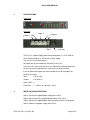
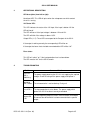
SS-12
User Manual
DOC. NO: SS-12-14 (Rev. 01)
Page 1 of 5
SS-12 USER MANUAL
Revision History
Revision 01
Original document
January 2008
CONTENTS
1.
SPECIFICATIONS ......................................................................................................... 3
2.
INSTALLATION INSTRUCTIONS .................................................................................. 3
3.
OPERATIONAL DESCRIPTION .................................................................................... 4
4.
TROUBLESHOOTING ................................................................................................... 4
5.
CONTACT DETAILS...................................................................................................... 5
DOC. NO: SS-12-14 (Rev. 01)
Page 2 of 5
SS-12 USER MANUAL
1.
SPECIFICATIONS
Front View
Side View
Output 3
Output 4
Output 5
Output 2
Output 1
- 12v +
12V Input
The SS-12 is a power supply splitter designed to power 1 x SS-87 SME or
SS-87 Standard and/or 4 x SS-10 from a single supply.
The unit has 1 input and 5 outputs.
All outputs are current limited to a maximum of 1A at 12V.
In the event of a short circuit the SS-12 will switch off the specific output and
will then restart the output when the short circuit has been removed.
If one or more of the outputs are short circuited the rest of the outputs will
continue to function.
Input :
12V @ 2.5A
Outputs :
12V up to 1A
Status LEDs : 8
Dimensions : L - 135mm W - 90mm D - 25mm
2.
INSTALLATION INSTRUCTIONS
Step 1: Connect the supplied power supply to the SS-12.
Step 2: Connect one of the supplied power cables to the SS-12.
Step 3: Connect the supplied power cable to the device which needs power.
Step 4: Switch on the power supply of the SS-12.
DOC. NO: SS-12-14 (Rev. 01)
Page 3 of 5
SS-12 USER MANUAL
3.
OPERATIONAL DESCRIPTION
LED description (from left to right):
Heart beat LED: This LED will pulse when the microprocessor which controls
the unit is running.
12V Status LED:
This LED indicates the status of the 12V input. If the input is bellow 12V the
LED will be off.
The LED will be on if the input voltage is between 12V and 13V.
The LED will blink if the voltage is above 13,5V.
Output LEDs (1 -5): These LEDs correspond to the 5 outputs of the SS-12.
If the output is working correctly the corresponding LED will be on.
If the output has been short circuited or overloaded the LED will be ‘’off’’.
Fuse status:
This LED will switch ‘’on’’ if the input protection fuse has been blown.
The LED must be ‘’off’’ for the SS-12 to work.
4.
TROUBLESHOOTING
Problem
Cause and Solution
12V STAT
LED is
off/blinking
The power supply powering the SS-12 is not supplying the required
voltage. Check the rating on the power supply and replace it.
Heartbeat
LED is off/on
The microcontroller is not functioning. Faulty unit.
Fuse LED is
on
The input protection fuse has blown. The power supply which
powers the SS-12 has been severely overloaded.
Output LED
is off
The corresponding output has been short circuited or overloaded.
Disconnect the device which has been connected to the specific
output.
DOC. NO: SS-12-14 (Rev. 01)
Page 4 of 5
SS-12 USER MANUAL
5.
CONTACT DETAILS
Office:
23 Botha Avenue
Lyttelton Manor
Pretoria, Gauteng
South Africa
Tel:
+27 12 664 4644
Fax: +27 86 614 5625
E-mail: [email protected]
Postal address:
Postnet Suite 48
Private Bag x 1015
Lyttelton, 0140
Pretoria, Gauteng
South Africa
Sales Support:
South Africa
E-mail: [email protected]
United Kingdom
E-mail: [email protected]
Technical Support:
E-mail: [email protected]
DOC. NO: SS-12-14 (Rev. 01)
Page 5 of 5