1
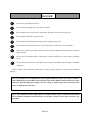
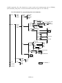
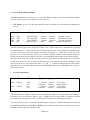
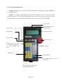
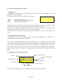
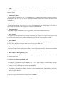
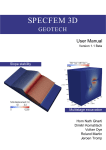
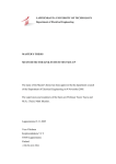
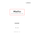
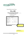
Advanced Motion Control Software
Fics-III
Programming Manual
(Ver.2.30)
(Fics-Atoms Series Controllers)
(Fics-SRing Series Controllers)
(Fics-PDS/3 Systems)
-DATA-
PGM=001
DYNAX
FICS
STEP Command
ORDER
____X___ ____Y___ ____Z___ ____W___ ____U___
____V___
0001 PTP . ABS [XYZ]
+9999.99 +9999.99 ........
0002 PTP -> ABS [WUV]
........ ........
+9999.99
0003 TIMER = 99.99sec
0004 OUT
01-0:ON 02 -7:ON 00-0:OFF 00-0:OFF
00-0:OFF 00-0:OFF
0005 TIMER = 99.99sec
0006 OUT
01-1:ON 02 -2:ON 00-0:OFF 00-0:OFF
00-0:OFF 00-0:OFF
0007 CALL
999
0008 IF
DI:01-1
IS 0
THEN GOTO 9999
ELSE
WAIT 999sec
0009 CALL
999
0010 PTP . ABS [XYZ]
........ ........ +9999.99
0011 OUT
01-1:ON 02 -2:ON 00-0:OFF 00-0:OFF
00-0:OFF 00-0:OFF
0012 TIMER = 99.99sec
0013 OUT
01-0:ON 02 -7:ON 00-0:OFF 00-0:OFF
00-0:OFF 00-0:OFF
0014 CALL
999
0015 END
1:AUTO
2:STEP
3:EDIT
5:BCOPY
10:CLR
6:PCOPY
-DATA-AUTO STEP PTP
PGM=100 X=+xxxx.xxmm
N=0001 Y=-yyyy.yymm
ABS .
[XYZ(W)]
8:FIND
DYNASERVO Inc.
http://www.dynaservo.com
Copyright @2002 DYNASERVO Inc.
-INTRO 1-
About This Manual
This manual describes system setup and programming using Fics-III, advanced motion control
software. Specifically, the following issues are addressed:
o A brief introduction to DYNASERVO motion control products including servomotors, drives,
controllers, and handheld terminals.
o Features of Fics-III.
o System parameter setting using Fics-RT1.
o Fics-III programming using Fics-RT1.
Read this manual carefully to ensure correct use of the DYNASERVO Fics-series controllers.
Keep this manual in a safe place for future reference.
Related Technical Publications
The following technical publications should be used as reference material. Check carefully
specifications, restrictions, and other conditions of all motion control products before attempting
to use them.
o DYNASERVO Motion Control Products Catalog: Provides brief description of Fics-series
serial control type controllers.
o Atom-SRA/SLA User’s Manual: Provides detailed information on use of Atom-SRA/SLA,
Atom-mini/SLIM drives.
o Fics-RT1 User’s Manual: Provides detailed information on use of Fics-RT1 handheld
terminals.
o WinFics User’s Manual: Provides detailed information on use of PC-based Fics-III
programming tool.
-INTRO 2-
Important Safety Instructions
Before power on the drive, make sure that the power supply voltage is consistent with the voltage
specified on the name plate of the drive you purchased. Using the incorrect voltage could cause
serious injury, fire, electric shock, and/or damage.
Before power on the drive, make sure that the combination of your drive and motor is correct. Failure
to follow this instruction could result in injury, electric shock, fire, and/or mechanical damage.
Before power on the drive, make sure that the drive is wired correctly. Failure to follow this
instruction could result in injury, electric shock, fire, and/or mechanical damage.
Install an external emergency stop device so that you can shut off the power in any emergency case.
Failure to follow this instruction could result in injury, electric shock, fire, and/or mechanical
damage.
Ground the FG (earth) terminal of the drive. Failure to follow this instruction could result in electric
shock and/or mechanical damage.
The drive contains stored energy devices. Do not attempt to transport, wire or inspect the drive for 10
minutes after the power off. Failure to follow this instruction could result in electric shock.
An over-current protection, over-temperature protection and emergency stop should be installed.
Failure to follow this instruction could result in electric shock, injury and/or fire.
If drive error occurs, remove the causes for the error and secure the safety before restarting the
operation. Failure to follow this instruction could result in injury or mechanical damage.
Servo drive radiates heat as the motor runs. If it is operated in the closed electrical enclosure,
temperature in the electrical enclosure may rise. Cool the enclosure so that the ambient temperature
of the enclosure is within the working temperature of the drive: 0 ~ 55 degrees.
Keep drive away from exothermic bodies such as heater or large coil resistor.
When drive is not in use for a long time, turn OFF the power supply.
Before installing Fics-series controllers into a computer, make sure that the main power of the
computer has been turned off. Failure to follow this instruction could result in damage to the
computer and the controllers.
Static electricity is harmful to IC chips. Before installing Fics-series controllers into a computer,
make sure that the static electricity in your body has been discharged.
-INTRO 3-
DANGER!
Do not insert your hands in the drive.
Do not touch the rotating part of the motor in motion.
Do not touch the drive, motor and its regenerative discharge resistor since they are hot.
Do not modify, dismantle or repair the drive.
Do not block the heat dissipation opening or insert foreign objects into it.
Do not connect motor load before you are sure that the drive and motor work as intended.
After recovery from power failure, motor may start to rotate suddenly. Do not approach to the motor
and motor load.
Do not expose connecting cables to sharp edges, excessive pressing forces, heavy loads or pinching
forces.
Do not subject the product to water splash, corrosive gases, flammable gases and other combustible
substances.
Failure to follow these instructions could results in injury, electric shocks, fire, burns, and/or mechanical
damage.
Take every possible care to safeguard this product against unexpected action. Every effort is made to
ensure high quality of this product, but unexpected action such as high external electrical noise, static
electricity, abnormal input power supply, incorrect wiring, or defective parts may result in personal
injury or malfunction of the drive.
Due to the continuous software improvements & updates certain features contained in this manual
may be different from those incorporated into your product. Contact our sales office if you have any
questions.
-INTRO 4-
Part 1
Fics-III
Introduction
-INTRO 5-
-CONTENTS1: DYNASERVO Serial Motion Control Products Overview....................................................7
2: Motion Control System Configuration Using DYNASERVO Serial Controllers ................8
3: Fics-III Motion Control software ...........................................................................................10
3-1: Software Configuration of Fics-III.......................................................................................... 10
3-2: Fics-III Programming Examples ............................................................................................. 12
3-3: Fics-III: Programming Tools .................................................................................................. 14
3-4: Operations and Messages of Fics-RT1..................................................................................... 15
3.5: Information on the Screen of Fics-RT1.................................................................................... 15
3-6: WinFics: PC-Based Programming Tool.................................................................................... 16
4: Before Beginning Fics-III Programming ...............................................................................17
-INTRO 6-
1: DYNASERVO Serial Motion Control Products Overview
DYNASERVO offers a wide variety of high performance motion control products, ranging from AC servo
motors, servo drives, to motion controllers, handheld terminals and touch screen terminals, which work
together to meet the requirements of the most demanding automation applications.
Miniature Drives
(Atom-SLIM/mini)
PC-AT,PCI bus Type
Controllers
(Fics-Atoms AT,PCI)
Standalone
Controllers
(Fics-Atoms SB)
Servo Drives
(Atom-SRA/SLA)
Programming Tools
(WinFics)
Fics-RT1
-INTRO 7-
Standalone 3-axis Step
Motor Controller and
Drive
2: Motion Control System Configuration Using DYNASERVO Serial Controllers
AC Servo
Motor Drive
Step Motor
Drive
M
M
Serial
Controller
Fics-III
Communication
Serial I/O
Expansion
Modules
Touch Screen
Terminals
Handheld
Terminals
The block diagram of the system configuration is shown above.
There are the following types of controllers:
(1). Standalone controller (Fics-Atoms SB, Fics-SRing SB);
(2). PC-AT/PCI/ISA bus type controllers (Fics-Atoms PCI, Fics-SRing PCI etc.);
(3). Smart drive type controllers (IMC-1X) which integrate a motion controller, a single axis servo drive,
and 24DI & 16DO in one compact package;
(4). Touch screen terminal type controllers (Fics-TPC1, Fics-TPC4, Fics-TPC5) which integrate color or
black & white touch screen with motion controller in one package;
(5). Handheld terminal type controller (Fics-TC1) which integrates handheld terminal with motion controller
in a single unit.
Some of the features of DYNASERVO motion controllers are listed below.
-INTRO 8-
Control of systems with up to 16 axes, integrating AC servo motors, and/or stepper motors
RS485 multi-drop or RS422 serial ring communication links
Linear and/or circular interpolations
High precision PTP control
Equipped with Fics-III (IV) or Ladder Motion language
Windows DLL for PC-based control
o Expandable 256 DI/DO with high speed serial communication.
o Easy operation and programming with Fics-RT1 and Windows programming tool WinFics
o Palletizing and coil winding software packages
o Programming in natural language
Detailed features of Fics-III are explained later in this section.
o
o
o
o
o
o
The key technologies which distinguish DYNASERVO controllers from other motion controllers are:
The custom CPU, integrating Hitachi SH RISC CPU and DYNAX 7260 pulse counter LSI and 7180
communication LSI.
2. The advanced motion control software Fics-III which was developed and refined by DYNAX for over a
decade. Using Fics-III dramatically reduces system integration time, which lowers total system cost.
1.
DYNASERVO controllers communicate with DYNASERVO drives via RS485 at the speed of 625kbps or via
RS422 at the speed of 2.5Mbps. These widely used industrial communication protocols ensure system reliability,
and their high-speed enables up to 8-axis synchronous control.
DYNASERVO standard AC servo drives, Atom -SRA/SLA series, are OEM manufactured by Panasonic. They
incorporate 32-bit RISC CPU and DYNASERVO advanced servo control algorithm, enabling them to achieve
+/- 1 pulse control accuracy. Atom-SRA/SLA drives can be linked together via RS485 or RS422 to form a
network, or they can operate as standalone units providing up to 256 indexing positions.
DYNASERVO other series of AC servo drives are Atom-SLIM/mini. Their extremely compact size allows
them to be mounted right next to the motors they control, thus reducing the length of encoder wiring and
improving system reliability.
DYNASERVO controllers are capable of controlling step motor drives. This feature allows greater flexibility
in design of complex motion control systems.
DYNASERVO serial I/O modules communicate with DYNASERVO serial controllers via RS422 at the speed
of 1.25Mbps. DYNASERVO offers wide selection of I/O modules equipped with various I/O configurations
and different connectivity options. The following table lists these modules.
Module Name
Fics-IOM/16.16RS
Fics-IOM/16RI
Fics-IOM/16RO
Fics-IOM/16.16CN
Description
16 opto-isolated DI and 16 relay DO with 16 fuses, screw terminal type
16 relay inputs
16 relay outputs
16DI/16DO (all opto-isolated with LED indicator), plug terminal type
-INTRO 9-
DYNASERVO standard AC servomotors are manufactured by Panasonic. Panasonic utilizes segmentation
winding techniques in their production, thus creating a very powerful yet very compact AC servo motors.
3: Fics-III Motion Control Software
DYNASERVO advanced motion control software, Fics-III, integrates key functions of motion control, I/O
serial communications, and operator interface into a single programming language. Fics-III provides the
following functions:
o Motion Programming:
In addition to the standard PTP control and linear interpolation functions, Fics-III offers multi-axis circular
interpolations. DYNASERVO servo control algorithm guarantees ±1 pulse control accuracy enabling high
precision multi-axis synchronous control.
Fics-III supports pallet and matrix programming which is very effective for short distance multi-point
positioning.
Fics-III supports numerous user defined SYSTEM variables, MONITOR variables, and FLAGs, which
simplify system programming.
o Multi-task Programming:
A unique feature of Fics-III is it’s support of up to 8 tasks, which offers users great flexibility in designing
complex control systems. Task programs run in the background, but can communicate with the main program
using FLAGs. Task programs play an important role in monitoring I/O sequences, which are independent of
servo control sequences. There is a special task called system task, which is automatically executed when power
to the controller is turned on.
o I/O Access:
Fics-III supports direct access to Fics-series controller ’s on-board I/O and to serial expansion I/O modules.
o Parameter Setting:
Fics-III supports easy setup of motion parameters such as resolution of encoders, lead of ballscrew connected
to motor shaft, acceleration/deceleration time, maximum speed, etc. Servo control parameters such as
proportional, integral and derivative gains can be easily tuned to provide best motion performance.
o Manual Teaching
PTP positions can be numerically programmed from DYNASERVO handheld terminal such as Fics-RT1, or
manually taught by jogging each axis to the desired position.
3-1: Software Configuration of Fics-III
Fics-III is configured as a tree structure as shown in Figure on the next page. Commands under [SYS] are
designed for the purpose of system setting and are shown in another tree (see part 2, Fics-III System Setup).
Commands in the rectangle box are options. If Fics-RT1 is used as programming terminal, the function keys
<F1>,<F2>,<F3> correspond to the upper 3 menus such as [AUTO], [MANU], [SYS], or [AUTO],[DATA],
-INTRO 10-
[COPY], respectively. The <F6> function key is used to switch to the remaining menus such as [TURBO],
[OUT] and [M1], [M2], [M3]. To return to the menus located on the upper tree use <CLR> key.
<Fics-III Command Tree (programming menus and commands)>
AUTO
MANU
MODE
STEP
[MANU]
[AUTO]
STEP
PTP
INC/ABS
PMODE
VAR/CON
ORDER
AXIS
TIMER
OUT
CALL
[AUTO]
DATA
VAR/MON/CON
AXIS
WAIT
I/O
MONX
ON/OFF
VAR/CON
MODE
ATOM
VAR/CON
TASK
VAR/CON
IN
M1
COPY
GOTO
IF
VAR
BIT
VAR/FLAG
N.+
N.-
STOP
DO
MON
SPEED
VAR
REPT
M2
REM
ORG
M3
TURBO
SYS
EEPROM
OUT
AXIS
PRM
RESET
OUT1
OUT2
OUT3
VAR/CON
SLOW/FAST/RATE
CON
VAR
FLAG
DI
BCD
DO
LOW
POS
HIGH
REM
MES
AXIS ERR
EMG
MTRIX
MFB
•yDDA•z
•yCNTR•z
C-V/V-C/VAR/CON
MODE
TIMER
SET
VAR/CON
ADD
N.+
N.-
SET
ADD
SUB
MUL
DIV
MON
N.+
N.VAR/CON
ATOM
VAR/CON
=
<>
>
<
VAR/CON
VAR/CON
=
<>
>
<
ON/OFF/REM
N.+
N.VAR/MON/CON
PTP
P.+
P.ATOM Fics-Atoms‚Ì‚Ý
•yFILE•z
-INTRO 11-
3-2: Fics-III Programming Examples
Fics-III programming is extremely easy. It is just like BASIC, perhaps even easier than BASIC language.
Let’s take a 2-axis system as an example to see how easy it is.
1.
PTP control: to move from the current position to the next position, one of the following commands can
be used.
1
STEP
0001
0001
0001
0001
2
COMMAND
PTP
PTP
PTP
PTP
.
.
-->
.
3
ORDER
4
__X__
ABS [XYZ(W)]
INC [XYZ(W)]
ABS [XYZ(W)]
ABS [XYZ(W)]
__Y__
DESCRIPTION
+0010.00
+0010.00
(Absolute Position)
+0010.00
+0010.00
(Incremental Position)
+0010.00
+0010.00
(P- Mode Positioning)
VAR10
VAR20
(Variable Assignment)
The first column represents the program step number. The second column is the command name. Following
the command name, a “.” means the next step of the program will not be executed until the completion of the
execution of the current step of the program. In contrast, the symbol “->” implies that the next step of the
program can be executed while the current step is running. ABS/INC simply specifies whether the desired
position is an absolute position relative to the home or an incremental position relative to the current position.
[XYZ (W)] denotes the order of PTP execution of each axis. [XYZ] means the PTP control of X, Y, and Z-axes
can start at the same time. [XY->Z] means the PTP control of Z axis will not start until the completion of PTP
control of X and Y axes. The numeric data under “_X_” and “_Y_” denote the desired positions of PTP control,
either absolute or incremental. Instead of directly entering digital numbers here, VARIABLEs can be used, as
shown in the last line.
2.
Circular interpolation:
1
STEP
2
COMMAND
0001
CIRCLE
0001
CIRCLE
3
TYPE
ABS
V=01
INC
V=01
4
__X__
__Y__
c: +0010.00
0005.00
e:+0020.00
+0010.00
c: +0010.00
0005.00
e:+0020.00
+0010.00
DESCRIPTION
(First Point)
(Second Point)
(First Point)
(Second Point)
The command name “CIRCLE” stands for circular interpolation “ARC” for arc interpolation. The positions to
be followed can be specified with “ABS” or “INC”. In addition to the present position, two points are required
for circular or arc interpolations. “V=01” specifies the index number of the interpolation velocities.
Note that users never have to remember command formats in programs. Command formats are fixed and will
be automatically displayed on Fics-RT1 or WinFics screen. All the user has to do is to select the order or type
and enter the desired data in the data input field.
-INTRO 12-
3.
Other typical motion control commands:
COMMAND
LINE
IF … THEN
GOTO
CALL
TASK
ORG
TIMER
IF DI … THEN
OUT
WAIT
SPEED
REPEAT
MATRIX
TBL
MFB
NOP
DESCRIPTION
Linear interpolation
Conditional branch
Unconditional jump to step number
Call subroutine
Start a task program
Origin-Return (Homing)
Wait a specified time period (min=0.01second)
On the condition of DI, jump
ON/OFF digital output bits
Wait until conditions are satisfied
Specify PTP velocity
Repeat specified step number for a number of times
Matrix data input for pallet programming
Handle an array of data including coordinate data
Access analog input/output module
No operation
-INTRO 13-
3-3: Fics-III: Programming Tools
Fics-III programming can be performed with either DYNASERVO programming terminal Fics-RT1 or a
PC + WinFics software.
Fics-RT1 is a portable programming and control terminal designed for control of robots and various
automated machines. The 80 character alphanumeric display meets all the requirements needed to program
using Fics-III. All system programming and parameter settings can be performed using Fics-RT1.
Auto execution
Home search
Manual operation and
programming
Run program
Parameter setting
Stop running
Emergency stop
Function keys: F1, F2, and
F3 corresponds respectively
to AUTO, MANU And
SYS
Jog keys
Numeric keys
Cancel operations
Save program and go to next
program step
Plus/minus sign and move back
in the programming menu
-INTRO 14-
3-4: Operations and Messages of Fics-RT1
<< Initial Screen. >>
If Fics-RT1 is connected correctly to Fics-series controllers, the initial screen of Fics-RT1 after power-on
looks like the screen on the right.
Use function keys to select menus for various operation modes.
-AUTO- AUTO MANU SYS
== Fics-III [V2.32]==
AUTO:
Automatic operation mode
DYNAX Corporation
MANU:
Manual operation mode, programming mode
Copyright(C)
94-2002
SYS:
System parameter setting mode
In this initial state, it is possible to perform JOG operation and homing. If the current program is a main
program, the system switches to automatic operation mode after homing is completed.
If homing is not completed, ‘ORIGIN ERROR’ error occurs when trying to switch to automatic operation
mode (except when all axes in the system are set as “homing not needed”).
When the system is not in automatic operation mode and the <START> key is pressed, ‘NOT READY’ error
occurs.
<<Manual/Automatic Mode Switching>>
In Fics-III, it is possible to switch between modes using external DI (digital inputs), in addition to the
switching method using function keys as stated above.
The ON/OFF of manual/automatic mode switching is represented by 1 or 0. Mode switching by digital inputs
is only valid in initial, manual, and automatic menus when the program is not running. The priority of manual
mode selection is higher than automatic mode selection. Manual mode is a default selection except in case
where the digital input corresponding to manual mode selection is OFF and the digital input corresponding to
automatic mode is ON. In system mode or programming mode, the digital inputs for mode switching are
ignored.
3.5: Information on the Screen of Fics-RT1
Function Key Menu
Mode
Program Number
-AUTO- AUTO MANU SYS
PGM=001 X=+xxxx.xxmm
N=0001 Y=+yyyy.yymm
Step-Data Display
Field Input Area
Step Number
Help and Error Message Area
Skip Indicator
The above figure illustrates the on-screen information for a typical PTP program step data.
-INTRO 15-
o Mode
Indicating AUTO mode for automatic operation, MANU mode for programming, or SYS mode for system
parameter setting.
o Function Key Menu
Showing usage of function keys <F1>-<F6>. Mode, menu, or command names of the command tree structure
are displayed in this area. Use <F6> key to display the remaining menus if there are more than three menus
(commands).
o Step Data Display
In data input and display area (from rows 2 to 4), programming step data is displayed in DATA mode or
AUTO mode, and parameter data is displayed in SYS mode and other modes.
o Program Number
In Fics-III, program is identified by a three-digit number, which is also called program name.
o Step Number
A program is a list of sequential steps, which are identified by step numbers. It is easy to insert or delete a step
or steps, and step numbers will be updated automatically even if they are used in GOTO-commands.
o Skip Indicator
When a program step starting with the symbol ‘/’ it is a comment step, implying that this step will be skipped
in AUTO mode. Skipping of a step can be set or reset by pressing <SKIP> key.
o Field Input Area
Data can be entered into the field input area when the cursor is blinking. Data in the field can also be modified
by numeric keys. To move cursor between fields, press “<= “ or “=>” keys.
o Help and Error Message Display Area
The last row of the data input area is also used to display error messages when an error occurs. It is also used
to display help messages.
3-6: WinFics: PC-Based Programming Tool
DYNASERVO programming software WinFics runs on a PC under Windows (95/98/NT/2000) operating
systems. This programming environment has several advantages over Fics-RT1:
o a large color screen allowing easy program copy and editing.
o Easy operation using function keys, numeric keys and mouse.
o Flexibility in uploading/downloading parameters to/from controllers using DYNASERVO CBIC-MFC
PCMCIA card or RS232C.
o Programs and parameters can be saved to and loaded from floppy disks.
See the cover page of this manual for a sample screen of WinFics.
-INTRO 16-
4: Before Beginning Fics-III Programming
In the following chapters, the system parameter setting is introduced first, then Fics-III programming issues
are explained. Make sure that you understand the motion system that you intend to control, and that all system
parameters are properly set before you begin programming. Pay special attention to the following points:
1. Your motion control products may have preset system parameters and/or preinstalled application programs.
Do not initialize the system before proper check.
2. Make sure that the setting of the number of axes and the number of units matches your physical system.
3. Make sure that “motor type number” is properly set (see servo drive manuals included with servo drive.)
4. Make sure that the coordinate systems are properly set for each axis.
5. Make sure that the mechanical parameters such as encoder resolution, lead of ball screw, etc. are properly
set (see 6.1: Setting Mechanical Parameters, part 2)
6. Make sure that all programmed system parameters match your physical system.
-INTRO 17-