1
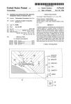
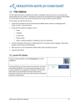
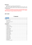
lllllllllllllllllllllllllllll?Illllllllllllllllllllll
United States Patent [191
[11] Patent Number:
Higgins et a].
[45]
[54]
Date of Patent:
5,477,241
Dec. 19, 1995
METHOD OF RESETTINGA COMPUTER
5,051,929
VIDEO DISPLAY MODE
5,065,346 11/1991 Kawai et a1.
9/1991 1116 m1. ............................. .. 364/521
395/128
5,119,081
6/1992 Ikehira ........... ..
340/723
7/1993 gigs
Kerr eetet
........
a1.a1- ..-
395/157
[75]
Inventors: voun’
Paul -J;Petaluma’
Higgins, Sebastopol;
both of Calif‘
1 Scott D.
5,227,771
,
,
[73]
Assignee: Binar Graphics Incorporated’ San
5,265,246 11/1993 L1 etal. ................................ .. 395/600
Rafael, Calif.
OTHER PUBLICATIONS
[211 APP1-N°-- 124,386
[22] Filed:
Sep' 20’ 1993
pp. 66-69, 86-87, 90-91, 9499, 176-181.
Primary Examiner—Richard Hjerpe
[51]
Int. Cl.6 ..................................................... .. G09G 5/00
Assist/1m Examiner4teven J- 59915
[52]
US. Cl. ........................ .. 345/127; 345/132; 345/902;
Attorney’ 488"" 0* F‘""—H1°kma“ 8‘ Beyer
_
Aldus Photostyler, User Manual, Second Edition Jun. 1992,
395/155
[58]
[57]
Field Of Search ................................... .. 345/118, 119,
’
A SCI'CGH commanding Utility is provided that PCITIlltS a user
’ 156’ 157’ 161’ 128’ 139 102’
’
[56]
’
’
’
to select the number of display pixels are used to represent
’
a designated unit length of printed output in a computer
References Cited
system’s display screen. The screen commander is arranged
to determine the location(s) at which the operating system
U-S- PATENT DOCUMENTS
4,672,683
4,831,556
ABSTRACT
stores the current DPI setting. Then, when a command is
6/1987 Matsueda ................................ .. 382/57
5/1989 001.10 .................... .. 345/127
received from a user to adjust the DPI Settings’ the desired
new DPI Setting are stored in the current DPI Swings
19cati0n(S)
4,837,635
6/1989 Santos .................. .. 358/401
4,931,956
6/1990
4,954,970
9/1990 Walker et al. ...................... .. 364/521
Stapleton
. ... ..
. . . ..
I
364/521
20 Claims, 8 Drawing Sheets
Program Manager
I‘:
file Qptions window ?elp
l70
DPI \ALYZARD
-
75
7
ACurrent Y[Q5l"7gurrent X1361’ iii-(E1991
:-
92,
—_
' 81
8°
D aB
3
Default Y
Default x
' ‘i '
—
Microsoft
Dash 1
Access
Wi
System
Acc
__—'
I:
Release Notes
El
“m
.587
:_—
WinBook
-D
86
,: 5
_
E
'*
,|.|.|.|.|.|.|.l~83
AnyView
U.S. Patent
Dec. 19, 1995
Sheet 1 of 8
QB
mm
5,477,241
mm
mm
AI Y
CLLLHI_CLILUCE<_I
mDU)
\ow
91
:A1l0i
N1‘
1‘
m
OE<m>w¥
mm
3\
\
E LU E O r: >-
no 2 a)
r
2/
US. Patent
I
Dec. 19, 1995
Sheet 2 of 8
5,477,241
Program Manager
‘I:
File Qptions Window Jielp
48\"
Anyview
j
5
l024x768
16 colors
56
Microsoft
Access
Virtual
Desktop
256 colors
58
32K colors
57
[ET
Bird's Eye
View
AnyView
System
u
WinBook
.
M
km
I
50
7g. 2
.11
5g
.1
<2
5654 57 52
US. Patent
Dec. 19, 1995
I
Sheet 3 of 8
5,477,241
Program Manager
‘I:
file Qptions window ?elp
[70
I
DPI WYZARD . '
-—
75
7
'
84""- iCurrentYlEQi" CurrentXlBE’ E91
I] ""
New YIBEJQ New x
r___
.. w
a
III
E -
l
MiCI'OSOft
Access
D II
System
P“
.
-
9
"I
——-
“
- I)
86
-
.
.
l
'
1’
l
|
.
'
Release Notes
WinBook
so
~‘8/
"
II
Q
92'
.‘j
_
Win
Acce
81
—
Dashb
Cancel | :I.
77
R
.
._.
“
AnyVicw
83
US. Patent
Dec. 19, 1995
I
Sheet 4 of 8
5,477,241
Program Manager
II:
File Qptions Window Help
,70
DPI WYZARD
_
7
E
New “@179 New X
7
A Current YIBET" 5Current XEST irqgwm
-E :I.
921
I]
olors
n E I
II I
Microsoft
Dash -
Access
Wi
System
Acc
Release Notes
WinBook
US. Patent
Dec. 19, I995
I
Sheet 5 of 8
5,477,241
Program Manager
I
_f‘ile Qptions window Help
/95
Y
ElDPI Options
|
_ [1 Current Resolution Ila-59%| :]
——
@640 x 480
:II
—— I 0800 x 600
‘—
O 1024 x 768
64 -
_
Microsoft
Access
Dash
Acc
96
@ 01m
D
Q1280 x1024
[:1 Disable All DPLWYZARD Effects 3
_
'
-- "
Release Notes
WinBook
E]
—
Wi
_ —'
System
IEEE
.
.7
AnyView
I l
I
I
I
I
I
| I
US. Patent
Dec. 19, 1995
Sheet 6 of s
'
101
Call DPI
/
Calibration
Function
Get Current
103
System DPI
Settings
Display Dialog
Box
ave New DPI 1
Settings Been
Entered?
109
Write Selected DPI
Settings Into System
& DPI Application
Data File
5,477,241
US. Patent
Dec. 19, 1995
Sheet 7 of 8
5,477,241
105
(Fig- 6)
130
as A New DPI Setting
Been Entered In The
Settings BOX?
136 \
132
Yes
NO
_
as A Slider Been Yes
Moved?
138
Change Value Of
"New" DPI Settings
To Inputted Value
__>
Dlsplay lnputted
Value In New
Value Box, Ruler
& Slider Bar
N0
as A Default Button Yes
Been Selected?
141
\
134
NO "
Display &
Yes
as "Option" "140
Process
een Selected?
Options Box
143
P
"""'
NO
Has Other
Yes
srimesii
Function Been
c act?
Selected?
Funct1on
146
142
NO
as "UK." Been
Yes
Selected?
(Fig 6)
N0
No
as "Cancel" Been
Selected?
148
7g. 7
109
Yes
US. Patent
Dec. 19, 1995
Sheet 8 of s
5,477,241
200
Activate
--202
Intermediary
Driver
Receive Driver
Function Enable
204
'
206
Return GDI Info Structure I
Save Default DPI Settings |_ 207
i
Look To See Where
208
DPI Settings Are Stored
& Record Offset
221
Activate
Screen
Commander
Utilit
223
‘ re There Any Save
DPI Settings For The
Current Resolution?
225
Write Saved DPI
Settings Into System
GDI Info Structure
@ Recorded Offset
$9]. 8
5,477,241
1
2
METHOD OF RESETTING A COMPUTER
VIDEO DISPLAY MODE
this procedure is slow and cumbersome. Further, when the
resolution is changed, the user is limited to the DPI associ
ated with the newly selected resolution, which may not be
satisfactory.
BACKGROUND OF THE INVENTION
In view of these drawbacks, a system arranged to give the
user the ability to control the number of display pixels that
The present invention ‘relates generally to a mechanism
for adjusting selected video display characteristics in a
computer system. More particularly, an arrangement for
are used to represent a given distance of print output would
be desirable. Accordingly, it is an object of the present
invention to provide such a system.
controlling the number of dots that are displayed on a video
screen per inch of printed output (DPI) is described.
In most modern personal computer systems, the video
display monitor is controlled by a dedicated video card that
has a plurality of software based display drivers. The oper
atirrg system selects which display driver is to be used and
SUMMARY OF THE INVENTION
To achieve the foregoing and other objects and in accor
dance with the purpose of the present invention, a screen
commanding mechanism and user interface is provided that
permits a user to select the number of display pixels are used
to represent a designated unit length of printed output in a
computer system’s display screen. The screen commander is
arranged to determine the locations at which the operating
then stores information about the screen characteristics (as
dictated by the selected driver). That information is then
used by both the operating system and any application that
has the need to know any screen characteristics. One char
acteristic that the display driver must set is the number of
system stores the current DPI setting. Then, when a com
mand is received from a user to adjust the DPI settings, the
desired new DPI setting are stored in the current DPI settings
location.
display pixels that will be used to represent one inch of
printed output. This is commonly referred to as the display’s
DPI (dots per inch). The DPI characteristics must be set in
both the horizontal (X) and vertical (Y) directions. Although
In a preferred user interface aspect of the invention, a DPI
it is not required, it is common to use the same DPI value for 25
settings dialog box is displayed when the user chooses to
both the horizontal and the vertical directions so that the
review or alter the DPI settings. In a preferred embodiment,
displayed image is not distorted.
the dialog box includes a pair of graphic rulers that display
respective horizontal and vertical desired DPI settings in the
For a variety of reasons, the number of dots per inch
indicated by the display driver to represent an inch of output
form of rulers. Each ruler may have an associated slider bar
having a slider thereon that the user may use to adjust the
commonly occupy more than an inch of screen space. One
explanation is the assumption that the screen resolution is
generally not as good as the resolution of printed matter so
it is easier on the user’s eyes when the displayed materials
are larger than the printed text. Another reason may be that
users tend not to sit as close to a video display as they would 35
hold a piece of paper. In any event, the values selected by the
display drivers are not always optimal for speci?c user
needs. For example, users of desktop publishing software
user to automatically select the default DPI settings as the
desired DPI settings.
In a preferred method aspect of the invention, the current
DPI setting are stored in a designated data structure, the
desired DPI setting are also stored in non-volatile memory
so that at system startup time, the system can be set up to
commonly prefer that the image displayed have exactly the
same measurements as the printed output. Other users may
wish to have the displays appear larger so that text can be
read more easily or may wish a page (or portion thereof) to
occupy a ?xed portion of the screen or the entire screen.
Currently, one of the most popular operating systems for
IBM PC compatible personal computers is the MS-DOS
based Windows operating system marketed by Microsoft
desired DPI setting. Additionally, a plurality of display
boxes may be provided for displaying the current and
desired DPI settings in alphanumeric form. In another pre
ferred embodiment, a button may be provided to permit the
automatically reload the last desired DPI setting associated
with the particular resolution.
45
BRIEF DESCRIPTION OF THE DRAWINGS
The invention, together with further objects and advan
tages thereof, may best be understood by reference to the
following description taken in conjunction with the accom
Corporation. In Windows, like most DOS based systems, it
is not possible to change the displayed DPI for any particular
display driver. The size of the displayed information can be
altered somewhat by a variety of stop gap measures. How
panying drawings in which:
FIG. 1 is a block diagram of a computer system that is
ever, none give the user real control over the display size.
suitable for operating the present invention.
For example, one common approach in word processing
applications is to change the font size of the text during
inputting and editing. However, requiring the user to change
FIG. 2 is a screen display showing a representative
opened window that contains a Windows based user inter
font sizes is inconvenient and can lead to all kinds of 55 face for a computer display mode controlling utility in
formatting di?iculties. Another approach is to switch the
accordance with the present invention.
screen resolution. However, (in order to switch the screen
FIG. 3 is a screen display showing a dialog box style user
interface that permits a user to set the number of dots per
inch that are displayed.
FIG. 4 is the screen display shown in FIG. 3 after the user
resolution, it is typically necessary to exit any open appli
cation(s), exit Windows in Windows based systems) and
then change the screen resolution in DOS. This is typically
accomplished by loading a new driver program, or in the
case of changing the screen resolution using a multi-reso
has altered the DPI settings.
FIG. 5 is a screen display showing a DPI Options dialog
lution driver, the application requesting the new resolution
saves the desired resolution values to the disk before exiting
Windows. After the new driver has been loaded (or the
appropriate resolution values saved), both Windows and the
desired application programs must be restarted. Obviously,
65
box suitable for use in a system capable of supporting
multiple screen resolutions.
FIG. 6 is a ?ow diagram illustrating a suitable process for
altering the DPI setting in a computer system.
5,477,241
3
4
application.
FIG. 7 is a flow diagram illustrating the user input
processing steps 107 and 108 of the process set forth in FIG.
6.
FIG. 8 is a ?ow diagram illustrating a method of recording
the default DPI settings and the location at which the DPI
In the described embodiment, the driver is set up some
what different than many display drivers. Speci?cally, at
Windows run time, only the intermediary driver utility is
installed. The intermediary driver utility is a small section of
code with a pointer table. The bulk of the code is saved in
driver “libraries” such that each supported color depth has a
settings are stored by the system.
FIG. 9 is a ?ow diagram illustrating a method of restoring
the DPI settings to user selected values after the operating
system has been restarted.
10
unique library. Thereafter, when Windows makes its ?rst call
to the driver, the driver library for the selected color depth
is loaded and initialized. The described intermediary driver
installation technique is particularly well suited for use with
DETAILED DESCRIPTION OF THE
INVENTION
As shown in FIG. 1, a computer system 10 suitable for
executing the present invention includes a central processing
unit (CPU) 12, a bi-directional memory bus 14 which
couples the CPU to memory 16 and memory mapped
peripherals 18, and a bi-directional peripheral bus 20 which
connects the CPU to a variety of peripheral devices. The
memory 14 typically takes the form of both read only
memory (ROM) and random access memory (RAM).
the present invention since it allows the DPI settings to be '
15
recorded regardless of which driver is selected, without
requiring each driver to be modi?ed to record the settings.
The application program based icon interface portion of
the present invention may be stored in the program manager
window 48 of Windows. The utility window 49 that contains
the utilities of the present invention is referred to as the
20
AnyviewTM utility window in the drawings. As seen in FIG.
2, the utility window 49 has a multiplicity of icons therein
that can be selected by the user. By way of example, the
utility window 49 may include a plurality of screen resolu
tion icons 50, a plurality of color depth icons 52, a zoom icon
54, a virtual desktop icon 56, a DPI calibration icon 57, a
25
bird’s eye view icon 58, and other icons 59 which permit the
user to control the video display in other manners. The
peripheral bus include a video card 22 which controls a
function and operation of the utilities represented by the
display monitor 24, a Winchester type hard disc drive 26, a
screen resolution icons 50, the color depth icons 52, the
?oppy disc drive 27 and/or CD ROM 28. Additionally, a
zoom icon 54, the virtual desktop icon 56 and the bird’s eye
keyboard 30 and a pointer device 32 such as a mouse or track
view icon 58 are described in applicant’s co-pending appli
ball are typically connected directly to the CPU 12. Both the
cation Ser. No. 08/023,945 ?led Feb. 26, 1993, now US.
keyboard and the pointer device are arranged to function as
Memory mapped peripherals typically include video adapt
ers and data storage devices. A variety of peripheral devices
can be coupled to the peripheral bus 20. By way of example,
peripherals devices that are frequently connected to the
Pat. No. 5,420,605, which is incorporated herein by refer
user input devices. As will be appreciated by those skilled in
ence.
the art, a wide variety of other peripheral devices can be
connected to either the peripheral bus or the memory bus and 35
In addition to the icon based user interface described
the buses which connect the described peripherals to the
above, a toolbar 60 is provided. The user may optionally
CPU can be switched and/or additional buses can be added.
have the toolbar displayed at all times. The toolbar 60 has a
number of icons therein. The user is permitted to add any of
The video display controlling utility of the present inven
the icons in the utility window 49 to the toolbar. When the
tion may be applied to a variety of computer systems
running a variety of diiferent operating systems. However, 40 user selects an icon in the toolbar, the corresponding func
tion is executed just as if the icon has been selected from the
for the purposes of illustration the described embodiment
utility window 49. Thus, the user is provided with a mecha
will take the form of a utility program for use with a personal
nism for adding icons to and removing icons from the
computer that is executing an MS-DOS based “Windows”
toolbar. The toolbar editing interface is opened by selecting
operating system marketed by Microsoft Corporation.
Accordingly, the described embodiment is icon-based which
45
an appropriate editing command from a pull down menu
gives the user quick access to its most often used features.
The described embodiment-of the present invention is
which displays a dialog box. The toolbar editing interface is
described in the referenced application.
divided into portions. The ?rst portion includes the user
interface which is based in an application program. For the
purposes of the description that follows, a general familiar
for the utility of the present invention. More speci?cally, the
The DPI calibration icon 57 activates the user interface
50
ity with the “Microsoft Windows Software Developers Kit,”
(SDK) version 3.1 (1992) which is published by Microsoft
Corp. is assumed. The second portion of the invention is
based in the display driver and is required to facilitate
DPI calibration icon represents a utility which is intended to
give the user the power and ?exibility to set the number of
pixels in the display monitor that are displayed to represent
a designated length of printed output when the displayed
information is printed. In the United States, the number of
communication with the computer hardware. For the pur 55 display pixels allotted per unit of printed output is usually
referred to as the number of dots (i.e. pixels) per inch, which
gives rise to the acronym “DPI”. The described feature has
several uses. For example, in windows applications, one
complaint that is frequently voiced by users of desktop
Corp. is assumed. Additionally, as is well know to those
publishing software is that what is displayed on the screen
skilled in the device driver programming for Windows art,
is not sized the same as the printed output. By giving the
the reference “Undocumented Windows” written by Schul
users the ability to calibrate the screen’s DPI, this problem
man et al. and published by Addison Wesley in 1992 is a
poses of the description, a general familiarity of the
“Microsoft Windows Device Drivers Developers Kit”,
(DDK) version 3.1 (1992) which is published by Microsoft
can be eliminated. Other users may wish to vary the dis
played DPI in order to increase or decrease the size of the
great help when writing driver level code and a generally
familiarity with its contents is assumed. Each of these
references is incorporated herein by reference. Familiarity
with the programming in the Windows operating system
environment will be assumed for the purposes of this
65
displayed information to meet a particular need, without
altering the screen resolution.
When the DPI calibration icon 57 is selected, a DPI
5,477,241
5
6
editing dialog box 70 is displayed. A representative dialog
options dialog box 95 to be displayed. Selection of the
“Help” button 94 is intended to provide the user with
box is shown in FIGS. 3 and 4. In the embodiment shown,
the dialog box 70 displays the current DPI settings in both
the horizontal (X) and vertical (Y) directions. The horizontal
setting 73 is labeled “Current X” and the vertical setting 75
assistance on the use of the dialog box 70.
The options dialog box 95 will be described with refer
ence to FIG. 5. The options box permits the user to select the
is labeled “Current Y” in the drawings. Additionally, any
newly selected DPI settings (77 and 79 for the new hori
zontal and vertical settings respectively) are displayed adj a
desired DPI settings for each resolution in a system arranged
to support a plurality of screen resolutions. As will be
appreciated by those skilled in the art, the default DPI
cent the labels “New X” and “New Y” respectively. Further,
settings are often varied based upon the screen resolution.
buttons 80 and 81 are provided to enable the user to
For example, windows based drivers typically set the DPI
settings to 96 dots per inch in resolutions bellow 1024x768
while resolutions of 1024x768 and above are typically set to
automatically reselect the original default DPI settings that
were provided by the display driver. The “newly selected”
DPI settings are also graphically displayed using rulers 83
and 84. The rulers 83 (for horizontal) and 84 (for vertical)
120 dots per inch. For a variety of reasons, the user may not
wish to have the same DPI settings for each potential
resolution, especially in systems having a screen command
are drawn to scale as seen by the display so that one unit
display length as shown on the ruler equals one unit length
of printed output. For the purposes of this discussion, the
unit length will be one inch, although any other unit length
could be used in its place. In the embodiment shown, quarter
ing utility that permits on the ?y resolution switching as
described in the above referenced co-pending application.
Therefore, the described embodiment permit users to vary
the DPI settings for each resolution. The options box permits
and half inch markers are made as well.
In order to input new desired DPI settings, the user may
20
either type the desired settings into the appropriate boxes 77
and 79, or may use the handy graphical rulers 83, 84 and
their associated slider bars 86, 87. To adjust the DPI settings
the users to adjust the DPI settings with respect to each
supported screen resolution.
The option dialog box 95 includes a resolution choosing
box 96 that lists each resolution supported by the driver. By
selecting a particular resolution, the user can adjust the DPI
settings associated with the selected resolution. After the
appropriate resolution has been selected, the user may enter
using the rulers, the user “grabs” the slider on the slider bar
and moves it. When the slider is moved, the length of the
DPI setting is adjusted accordingly. Thus, by way of
the chosen resolution by selecting the OK button 98. Alter
example, if a user wants the display to have identical
natively, if the user simply wishes to cancel the options box
dimensions as the printed output, the user can place a ruler
95, they may do so by selecting the Cancel button 99. When
against the screen and adjust the slider until an inch on the
30 either the Cancel or OK button has been chosen, the user will
screen equals an inch on the ruler. Proportional adjustments
be returned to dialog box 70 which permits editing of the
can be done in the same way. Alternatively, the user can
DPI settings for the selected resolution.
simply move the slider to a position that is subjectively
Referring next to FIGS. 6-9, a method of switching the
appealing. As the'slider is moved, the values of the corre
DPI settings in accordance with the present invention will be
described. Turning initially to FIG. 6, the process begins at
sponding DPI settings are displayed in the appropriate newly
selected DPI setting box 77 or 79. When the default buttons
80 and/or 81 are selected, the corresponding default values
are displayed in the associated ruler and newly selected DPI
setting box.
A representative change in the desired DPI settings is
shown in FIG. 4. As can be seen therein, the horizontal DPI
step 101 when the user enters a command that calls the DPI
calibration function. In practice, this is normally done by
40
settings has been changed from the original “default” setting
of 96 DPI (which is the “current” DPI setting) to a new
setting of 55 DPI. Similarly, the vertical DPI setting has been
changed from the default (again 96 DPI) to 49 DPI. As can
be seen in the ?gure, both the horizontal and vertical rulers
based operating system, this may be accomplished by mak
ing two “Get Device Caps” calls (one for each axis). Once
are redrawn to scale in order to give the user a graphical
image of the newly chosen settings.
the current settings have been obtained, the logic moves to
The manner in which the ruler is drawn is straight
forward. In essence, the reference (i.e. zero inches) is located
at a ?xed point within the dialog box. The ruled dimensions
are then calculated based on the “new” DPI settings. Then,
the properly scaled ruler is drawn. Thus, the inch mark is
drawn at a location that is X pixels (for the horizontal ruler)
or Y pixels (for the vertical ruler) away from the reference.
The location of the half and quarter marks are easily
calculated on a proportional basis. Then, as many additional
marks are drawn as are appropriate for the ruler which is of
a ?xed length within the dialog box.
The dialog box 70 also has four buttons labeled “OK”,
“Cancel”, “Options”, and “Help”. The “OK.” button 91 is
selecting the DPI calibration icon 57 that is located in either
utility window 49 or the toolbar 60. Alternatively, the call
could be generated by the acts of selecting a menu item in
a pull down menu, by inputting a keyboard commands or in
any other suitable manner. When the DPI calibration func
tion is called, the logic moves to step 103 where the current
system DPI settings are obtained. That is, the settings in both
the X and Y directions. By way of example, in a Windows
step 105 where it displays the dialog box 7 0. After the dialog
box has been displayed, the logic moves to step 107 where
any user inputs are processed. Newly selected DPI settings
will be among the user inputs. When the user is ?nished
making any inputs the logic effectively goes to step 108
where it determines whether the user has selected any new
55
DPI settings. The processing step 107 is completed when the
user selects either the “OK” button 91 or the “Cancel” button
92. In the described embodiment, when the dialog box is
displayed in step 105, the current DPI settings are inserted
as the initial “new” DPI settings. With this arrangement,
anytime the user selects the “OK” button, the system
assumes that there is a new entry and the logic proceeds
intended to be selected when the user is satis?ed with the
from step 108 to step 109. On the other hand, anytime the
selected DPI settings. Activation of the “OK.” button will
cause the newly selected DPI settings to be stored and
implemented. The “Cancel” button 92 is intended to be
selected when the user does not wish to change the current
DPI settings. Selection of the “Options” button 93 causes a
“Cancel” button 92 is selected, the logic assumes that no
new entries are desired and the result of step 108 is that no
65 new DPI settings are to be entered. In this case, the process
is completed. In step 109 the newly selected DPI settings are
written into the system and a DPI data ?le. After the newly
5,477,241
7
8
selected DPI settings have been stored, the DPI calibration
routine is completed.
The selected X and Y DPI settings are written into the
operating system by writing the desired value to the memory
other speci?c functions have been selected such as the
“help” function. If so, the selected function is processed as
necessary. If not, the logic moves to step 146 where it checks
to determine whether the “OK.” button has been selected. If
so, this indicates that the user is satis?ed with the “new” DPI
offset location where the DPI settings are stored. Of course,
the actual memory o?fset locations are expected to vary from
system to system, from machine to machine and even
between boots on the same machine with some operating
settings and the logic proceeds to step 109 (described above)
where the new DPI settings are stored. If the OK. button has
not been selected, the logic checks to determine whether the
“cancel” button has been selected. If so, the user is indicat
ing an intention to change the DPI settings at this time and
the entire process is completed. If neither the “OK.” nor the
systems. In many operating systems, such as DOS based
Windows systems, the operating system sends a request to
the display driver during initialization, asking the display
“Cancel” button has been selected, the logic loops back to
step 130 where it begins looking for new DPI setting
driver to give the system information about the video
display’s characteristics. Among the information returned
changes. This process is continued until either the “OK.” or
are value indicative of the DPI settings in both the horizontal
the “Cancel” button is selected.
and vertical directions. When this information is returned, it 15
In the foregoing explanation the process has been
is important for the screen commanding utility to detect
where the DPI settings information is stored. This is done at
described as if the checking routine is serial in nature and
system startup. That is, when the operating system is
launched. When the operating system is launched, the screen
commanding utility will record the o?fset in the GDI
(Graphic Device Interface) info structure (or its equivalent)
where the system stores the DPI settings. In most operating
skilled in the art, in practice such a checking algorithm is not
constantly running. However, as will be appreciated by those
speci?cally required. Rather, in practice, the various
described checking steps (i.e. steps 130, 136, 138, 140, 142,
146, and 148) are call routines which are executed when
called. The manner in which the functions are called is by
systems, this information is stored only at one location and
selecting their associated buttons or writing in their associ
will not be moved. Of course, if the information is stored in
ated
boxes.
more than one spot, it would be necessary to either record or 25
Referring
next to FIG. 8, a suitable method for detecting
search for the other locations as well.
the system’s storage location for the DPI settings will be
described. The method begins at the initiation system startup
(step 200). At some point during the startup, the driver is
activated when the system loads the speci?ed driver into an
When a particular application requires information about
the DPI settings, a request is made (a “Get Device Caps”
request in Windows) to the system to return these values.
The request is responded to by providing the values stored
in the designated DPI settings memory offset location.
Therefore, in order to change the DPI settings, the screen
commander application only need to write the desired DPI
settings in the designated memory offset location.
In step 109, the logic also saves the desired DPI settings
in a DPI Application Data File. As will be explained in more
detail below with reference to FIG. 9, this data ?le is used
initialization ?le. When Microsoft Windows is used as the
35
initialization ?le rather than a speci?c driver. Step 202. At a
later point, (step 204) the intermediary driver utility loads
to save the settings so that they can be reused after the
system has been shut down and rebooted.
Referring next to FIG. 7, the user input processing step
107 and 108 will be described in more detail. As indicated
above, the dialog box displays the current and “new” DPI
settings. The new settings are displayed in two manners. The
?rst is numeric representations in the boxes 77 and 79. The
second is a graphic representation in the form of rulers 83
and 84. The logic of the user input processing step in the
described embodiment is shown in FIG. 7. Initially, the logic
checks to determine whether a new DPI setting has been
entered. This can be done in three ways. The ?rst is inputting
a value directly into a new settings box. This is checked in
40
settings designated by the driver. The intermediary driver
45
machine and even between boots on the same machine with
50
setting is entered in any one of these manners, the logic 55
moves to step 132 where the value of the “new” DPI settings
is changed to the inputted value. Then, in step 134, the
inputted value (i.e. the revised “new” DPI setting) is dis
played in the appropriate new value box 77,79, in the
displayed and any user inputs are processed in step 14. If not
the logic ?ows to step 142 where it determines whether any
step 207. Then, in step 208, the intermediary driver utility
tracks the o?set in the GDI Info Structure where the DPI
settings are written. The actual memory offset locations are
expected to vary from system to system, from machine to
button which is checked in step 138. When a new DPI
In step 140 the logic determines whether the “option”
button has been selected. If so, the options dialog box is
the appropriate display driver. The driver then returns a
series of information about the display. This is written by the
system into a GDI (Graphical Device Interface) Info Struc
ture. Among the information returned are the X and Y DPI
utility records these settings as the default DPI settings in
step 130. The second is by moving the slider which is
checked in step 136. The third is by selecting a default
appropriate ruler 83 or 84 and the appropriate slider box
86,87. Thereafter, the logic moves to step 140. Similarly, if
no new DPI settings have been inputted, the logic will ?ow
to step 140.
operating system, the speci?ed driver is loaded into a
windows initialization ?le called “SYSTEMJNI”. In the
described embodiment of the present invention, an interme
diary driver utility is inserted between the system and the
driver. The intermediary driver utility is speci?ed in the
60
some operating systems. After the memory o?‘set location
has been recorded, the process is completed and the oper
ating system will continue with its startup routine.
It should be appreciated that when the computer system is
shut down, the current DPI settings will be lost by the
operating system. Thus, the next time the system is started,
the display will return to the default DPI settings. In many
situations, it may be desirable to automatically reset the DPI
settings to the values selected by the user when the system
is restarted. The manner in which this is accomplished will
be described with respect to FIG. 9. As indicated above with
reference to step 109, when new DPI settings are selected,
the values are saved in a DPI application data ?le. The DPI
application data ?le is stored in non-volatile memory. There
65
fore, when the operating system is rebooted, the information
will be available. Referring speci?cally to FIG. 9, the
automatic recall of the saved DPI settings begins when the
user launches the screen commander utility. Step 221. This
5,477,241
10
steps of:
storing the desired DPI setting in a settings ?le stored in
non-volatile memory; and
at a system startup time, checking the settings ?le to
can be done in any conventional manner. Then, in step 223,
the logic checks to determine whether there are any saved
DPI settings in the DPI application data ?le that correspond
to the current screen resolution. If so, the saved DPI settings
are written into the system GDI info structure at the recorded
deterrrrine whether a desired DPI setting has been
offset in step 225. When this is accomplished, the selected
DPI settings have been put in place and the recalling
function is completed. On the other hand, if in step 223 it is
stored and if so, storing the desired DPI setting in the
location of the current DPI setting.
4. A method as recited in claim 1 further comprising the
step of:
receiving an adjust DPI characteristic command from a
determined that there are no stored DPI settings, then the
recalling function is completed at that point.
user;
In one preferred embodiment, the driver is set up some
what diiferent than many display drivers. Speci?cally, at
Windows run time, only the intermediary driver utility is
installed. The intermediary driver utility is a small section of
code with a pointer table. The bulk of the code is saved in
driver “libraries” such that each supported color depth has a
unique library. Thereafter, when Windows makes its ?rst call
to the driver, the driver library for the selected color depth
is loaded and initialized. The described intermediary driver
installation technique is particularly well suited for use with
the present invention since it allows the DPI settings to be
recorded regardless of which driver is selected, without
requiring each driver to be modi?ed to record the settings.
On the other hand, in other driver setups, each driver could
be modi?ed to record the default settings and the location in
15
5. A method as recited in claim 4 wherein the desired DPI
settings are displayed in both textual and graphic form.
6. A method as recited in claim 5 wherein the displayed
graphic desired DPI settings include a vertically oriented
ruler and a horizontally oriented ruler.
7. A method as recited in claim 6 wherein the displayed
graphic desired DPI settings further include a pair of slider
bars each having an associated slider for adjusting the DPI
25
which the DPI settings are stored in the GDI ?le.
Although only one embodiment of the present invention
with some variations has been described in detail, it should
be understood that the present invention may be embodied
in many other speci?c forms without departing from the
spirit or scope of the invention. Particularly, in many
instances, the ordering of the steps can be altered without
defeating the purpose of the invention. Similarly, some steps
can be eliminated and others added without departing from
the scope of the invention. The invention has been described
in conjunction with an IBM PC compatible personal com
puter using an MS-DOS based Windows operating system.
However, the invention can also be adapted for use with
ture is a graphic device interface (GDI) information struc
ture.
11. A method of setting the display characteristics of a
video display wherein the video display is controlled by a
display driver having a predetermined default dots per inch
(DPI) setting indicative of the number of display pixels that
are to be used to represent a designated length of printed
output for a designated resolution, the default DPI setting for
an operating system being stored as a current DPI setting in
45
a designated data structure, the method comprising the steps
of:
determining the location of the current DPI setting in the
designated data structure;
operating system, the display driver having a predetermined
default dots per inch (DPI) setting indicative of the number
checking a known location in a selected data ?le to
determine whether a desired DPI setting has been
of display pixels that are to be used to represent a designated
saved; and
length of printed output for a designated resolution, the
when a desired DPI setting has been saved in the selected
default DPI setting being stored as a current DPI setting in
a designated data structure, the method comprising the steps
55
of:
determining the location of the current DPI setting in the
designated data structure;
data ?le, storing the desired DPI setting in the location
of the current DPI setting, whereby the DPI setting for
.7 the operating system are changed without requiring
currently open application programs to be exited.
12. A method as recited in claim 11 further comprising the
step of repainting the screen after the desired DPI setting has
60
been stored.
13. A user interface for permitting a user to adjust the
number of display pixels that correspond to a designated
length of printed output having dot per inch settings (DPI
entire operating system are changed without requiring
any currently open application programs to be exited.
2. A method as recited in claim 1 further comprising the
step of repainting the screen after the desired DPI setting has
been stored.
3. A method as recited in claim 1 further comprising the
8. A method as recited in claim 1 wherein the computer
system is arranged to support a plurality of resolutions and
each supported resolution has a default DPI setting associ
ated therewith, wherein the desired DPI settings are speci?c
to a particular resolution.
9. A method as recited in claim 1 wherein the designated
and the default DPI setting is stored when the operating
system is initiated.
10. A method as recited in claim 1 wherein the operating
system is Microsoft Windows and the designated data struc
the present examples are to be considered as illustrative and
not restrictive, and the invention is not to be limited to the
receiving an input indicative of a desired DPI setting; and
storing the desired DPI setting in the location of the
current DPI setting whereby the DPI settings for the
settings.
data structure is an operating system based data structure
other computers and operating systems as well. Therefore,
details given herein, but may be modi?ed within the scope
of the appended claims.
We claim:
1. A method of altering the display characteristics of a
video display of a computer system that is operated under
the control of an operating system, wherein the video display
is controlled by a display driver that cooperates with the
displaying a dialog box that displays the current DPI
setting in response to the adjust DPI characteristics
command; and
displaying the desired DPI settings input by the user.
settings), in a computer system having a display screen for
65
displaying images and an operating system for controlling
the execution of programs by the computer system, the
operating system being arranged to access a designated data
5,477,241
11
12
structure that includes a current DPI setting location that is
used to store information indicative of the number of display
number of display pixels that correspond to a designated
pixels that correspond to a designated length of printed
length of printed output having dot per inch settings (DPI
20. A user interface for permitting a user to adjust the
output for a designated resolution, the user interface com
settings), in a computer system having a display screen for
prising:
displaying images and an operating system for controlling
means for determining the current DPI setting location;
the execution of programs by the computer system, the
operating system including a designated data structure that
means for receiving an input indicative of a desired new
DPI setting; and
means for storing the desired new DPI setting in the
current DPI settings location whereby the DPI settings
for the operating system are changed without requiring
currently open application programs to be exited.
includes a current DPI setting location that is used to store
10
14. A user interface as recited in claim 13 further com
means for receiving an input indicative of a desired new
prising means for displaying the current DPI setting and the
desired new DPI setting.
DPI setting;
a pair of graphic rulers that display respective horizontal
and vertical desired DPI settings in the form of rulers,
15. A user interface as recited in claim 14 wherein the
display means includes a graphic display that displays the
desired DPI setting in the form of a ruler.
16. A user interface as recited in claim 15 wherein the 20
graphic display further comprising a slider bar having a
17. A user interface as recited in claim 15 wherein the
18. A user interface as recited in claim 14 further com
displaying the current and desired DPI settings.
DPI setting
desired DPI settings in alphanumeric form;
setting.
prising a default button for permitting the user to automati
cally select a default DPI setting as the desired DPI setting.
19. A user interface as recited in claim 14 wherein the
display means includes a plurality of display boxes for
each ruler having an associated slider bar having a
slider thereon that the user may use to adjust the desired
a plurality of display boxes for displaying the current and
slider thereon that the user may use to adjust the desired DPI
graphic display includes a pair of rulers including a hori
zontally oriented ruler and a vertically oriented ruler.
an indication of the number of display pixels that correspond
to a designated length of printed output for a designated
resolution, the user interface comprising:
means for determining the current DPI setting location;
25
a button for permitting the user to automatically select the
default DPI settings as the desired DPI settings; and
means for storing the desired new DPI setting in the
current DPI settings location, whereby the DPI settings
for the entire operating system are changed without
requiring currently open application programs to be
exited.