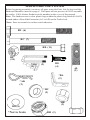
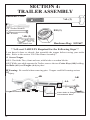
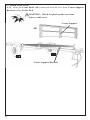
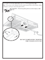
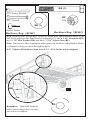
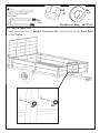
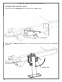
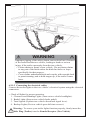
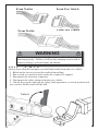
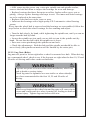
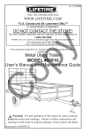
1
1/06/2010
®
VISIT THE LIFETIME WEB SITE:
WWW.LIFETIME.COM
**U.S. Canada and UK customers ONLY**
IF ASSISTANCE IS NEEDED,
DO NOT CONTACT THE STORE!
US and Canada customers call our customer service department at
1 (800) 225-3865
HOURS: 7:00 a.m. to 5:00 p.m. Monday through Friday (Mountain Standard Time)
UK customers call 01992 450333
op
y
**Call, or visit our Web site for Saturday hours**
**For customers outside the U.S., Canada, or UK, please contact the store for
assistance.**
C
Metal Utility Trailer
MODEL #0201
User’s Manual and Maintenance Guide
Warning: For safe operation of this trailer, be sure to read all
instructions and warnings. Failure to follow instructions and
warnings could result in property damage, serious injury and death.
Instruction #1029551 K
1
You could win $200!
Register your product at www.lifetime.com and receive three important
benefits:
1. You automatically will be entered to win $200 in our monthly drawing!
2. In the unlikely event of a product recall or safety modification, we can notify you
immediately and directly.
3. You may choose to receive Preferred Customer Announcements and promotions
regarding new Lifetime products.
C
op
y
www.lifetime.com
2
Lifetime Products, inc.
Metal Utility Trailer Model 0201
WARNING
This User’s Manual contains safety information and instructions for your trailer. You
must read this manual before loading or towing your trailer. You must follow all safety
precautions and instructions.
Lifetime Products, Inc.
Clearfield, Utah 84016-0010
P.O. Box 160010, Bldg. D-11
Phone: 1-800-225-3865
NHTSA Notification Statement:
If you believe that your vehicle has a defect that could cause a crash or could cause
injury or death, you should immediately inform the National Highway Traffic Safety
Administration (NHTSA) in addition to notifying Lifetime Products.
If NHTSA receives similar complaints, it may open an investigation, and if it finds
that a safety defect exists in a group of vehicles, it may order a recall and remedy
campaign. However, NHTSA cannot become involved in individual problems
between you and Lifetime Products.
To contact NHTSA, you may either call the Vehicle Safety Hotline toll-free at 1888-327-4236 (TTY: 1-800-424-9153), go to http://www.safercar.gov; or write to:
Administrator, NHTSA, 1200 New Jersey Avenue, SE., Washington, DC 20590.
You can also obtain other information about motor vehicle safety from http://www.
safercar.gov.
Call 1-800-225-3865 to reach our Customer Service line.
3
Table of Contents
SECTION 1: SAFETY INFORMATION
SECTION 2: TRAILER PARTS & HARDWARE
SECTION 3: PRE-TAKE-HOME ASSEMBLY
SECTION 4: TRAILER ASSEMBLY
4.1 Secure Tongue
4.2 Attach Rear Floor Extension
4.3 Attach Front Panel
4.4 Attach Side Panels
4.5 Attach Rear Side Extension Panels
4.6 Attach Corner Guards
4.7 Attach Rear Gate
4.8 Attach Spare Tire
4.9 Attach State License Plate
SECTION 5: TRAILER FEATURES
SECTION 6: COUPLING TO THE TOW VEHICLE
6.1 Using an Adequate Tow Vehicle and Hitch
6.2 Coupling and Uncoupling the Trailer
6.2.1 Trailer with Ball-Hitch Coupler
6.2.1.1 Before coupling the trailer to the tow vehicle
6.2.1.2 Prepare the coupler and hitch
6.2.1.3 Coupling the trailer to the tow vehicle
6.2.1.4 Rigging the safety chains
6.2.1.5 Connecting the electrical cables
6.2.1.6 Uncoupling the Trailer
SECTION 7: TIRE & SAFETY INFORMATION
7.1 Determining Correct Load Limit – Trailer
7.1.1 Trailers 10,000 Pounds GVWR or Less
7.2 Determining Correct Load Limit – Tow Vehicle
7.3 Glossary of Tire Terminology
7.4 Tire Safety - Everything Rides on It
7.4.1 Safety first–Basic tire maintenance
7.4.2 Finding your vehicle’s recommended tire pressure and load limits
7.4.3 Understanding tire pressure and load limits
7.4.4 Checking tire pressure
7.4.5 Steps for maintaining proper tire pressure
7.4.6 Tire size
7.4.7 Tire tread
7.4.8 Tire balance and wheel alignment
7.4.9 Tire repair
7.4.10 Tire Fundamentals
7.4.10.1 Information on Passenger Vehicle Tires
7.4.10.2 UTQGS Information
7.4.10.3. Additional Information on Light Truck Tires
7.4.11 Tire Safety Tips
4
7
11
14
18
18
20
22
24
26
32
33
35
39
40
44
44
44
44
45
45
45
46
47
48
49
49
49
49
49
52
53
53
53
54
54
54
55
55
55
55
55
57
58
58
7.4.11.1 Preventing Tire Damage
7.4.11.2 Tire Safety Checklist
7.5 Changing a Flat Tire
7.6 Checking the Tire Pressure
SECTION 8: LOADING THE TRAILER
8.1. Checking the Tongue Weight
8.1.1 Checking Tongue Weight — Using a lever and bathroom scale
8.2 Securing the Cargo
8.2.1 Loading Cargo
8.2.1.1 Preparing the Trailer for Loading
8.2.1.2 Loading the Trailer
SECTION 9: CHECK TRAILER BEFORE & DURING TOWING
SECTION 10: BREAKING IN A NEW TRAILER
SECTION 11: MAINTENANCE
11.1 Inspection, Service & Maintenance Summary Charts
11.2 Inspection and Service Instructions
11.2.1 Axle Bolts, Frame, Suspension, & Structure
11.2.2 Trailer Structure
11.2.2.1 Fasteners and Frame Members
11.2.2.2 Welds
11.2.3 Trailer Connection to Tow Vehicle
11.2.3.1 Coupler and Ball
11.2.4 Landing Leg or Jack
11.2.5 Lights and Signals
11.2.6 Tires
11.2.7 Wheel Rims
11.2.8 Wheels, Bearings and Lug Nuts
11.2.8.1 Unsealed Bearings (Hubs)
11.2.9 Lug Nuts (Bolts)
11.2.10 Suspension
SECTION 12: WARRANTY INFORMATION
58
58
58
61
62
64
64
64
64
65
65
67
69
70
70
71
71
72
72
72
73
73
73
73
74
74
74
74
75
76
80
5
This Page Intentionally Left Blank
6
SECTION 1: SAFETY
INFORMATION
SAFETY ALERT SYMBOLS AND SIGNAL WORDS
The safety information in this
manual is denoted by the safety
alert symbol:
The level of risk is indicated by the following signal words:
SIGNAL WORDS
Warning
Hazards or unsafe practices
which COULD result in severe
personal injury or death if the
warning is ignored.
Hazards or unsafe practices
which could result in minor or
moderate injury if the warning is
ignored.
If a label becomes unreadable, you can re-order them from Customer
Service:
Lifetime Products, Inc.
Clearfield, Utah 84016-0010
P.O. Box 160010, Bldg. D-11
or call
Phone: 1-800-225-3865
Caution
Warning Labels & Locations
2
2
1
6
7
3
5
4
1
7
Lug Nuts and Tire Pressure
WARNING
Tire, wheel or lug nut failure can cause loss of control.
Before towing, you must CHECK:
1. Tire pressure and tread.
2. Tires and wheels for damage.
3. Lug nuts for tightness.
For new and remounted wheels,
Retighten lug nuts at the first
10, 25 and 50 miles of driving.
ADVERTENCIA
Las fallas en las llantas, ruedas o tuercas a las llantas pueden provocar
pérdida del control. Antes de realizar un acarreo, DEBE REVISAR:
1. Presión y costura de las llantas.
2. Daños en llantas y ruedas.
3. Tuercas a las llantas bien apretadas.
Para llantas nuevas y reacondicionadas, apriete nuevamente las
tuercas a las llantas a los primeros 16 kilómetros, 40,2 kilómetros y 80,5
kilómetros de manejo.
© 2002 NATM
Lug Nuts TIGHT?
Tuercas a las llantas
¿BIEN APRETADAS?
Tires and Wheels OK?
Las llantas y ruedas ¿ESTÁN BIEN?
# 1027939
1
Re-order #1027939
The proper tightness (torque) for lug nuts is 95-120 ft./lb. Do not exceed 120 ft./lb.
Use a torque wrench to tighten the lug nuts. If you do not have a torque wrench, use
a lug wrench (from your tow vehicle) and tighten the nuts as much as you can. Then
have a service garage or trailer dealer tighten the lug nuts to the proper torque. See
the section “Tire and Safety Information” for more details concerning tire safety.
Lug nuts are also prone to loosen after first being assembled. When driving a new
trailer (or after wheels have been remounted), check to make sure they are tight after
the first 10, 25 and 50 miles of driving and before each tow thereafter.
Failure to perform this check can result in a wheel parting from the trailer and a crash,
leading to death or serious injury.
2
Securely Latching the Trailer Gate
CAUTION
SECURE GATES
BEFORE MOVING
TRAILER
PRECAUCIÓN
¡ASEGURE LOS
PORTONES ANTES
DE MOVER EL
REMOLQUE!
#1027932
Re-order #1027932
8
Ensure latches on trailer gate are secure during towing and
when not in use. The trailer gate must be locked down
during use and during storage. Failure to lock gate securely
could result in serious property damage, personal injury and
death. See the section “Trailer Features” for information
regarding latching the trailer gate.
Coupler, Load Weight and Distribution and Electrical
Connections
3
WARNING
ADVERTENCIA
Closed
Cerrado
ADVERTENCIA
WARNING
Uncoupling will cause trailer to come loose from tow vehicle. You must:
Attach hooks to tow vehicle
Sujetar los ganchos al vehículo remolcador
1. CHECK that ball load rating is same or greater than coupler load rating.
2. CHECK that ball size is same as coupler.
3. CLOSE COUPLER CLAMP on ball.
4. LIFT coupler upwards to test that it will not separate from ball.
5. LOCK coupler clamp with pin or padlock.
El desenganche hará que el remolque quede suelto del vehículo remolcador. Usted deberá:
Pin or padlock
1. VERIFICAR que la CAPACIDAD DE CARGA de la bola sea igual o mayor que la
Enough slack
In place
CAPACIDAD DE CARGA del enganche.
For turns
Colocar el candado o
2. VERIFICAR que el tamaño de la bola sea igual que el enganche.
Suficientemente
gancho
3. CERRAR el TORNILLO DE AJUSTE DEL ENGANCHE sobre la bola.
Cross chains
flojo para poder
Lift coupler to check
4. LEVANTAR el enganche para probar que no se separe de la bola.
Cruzar las cadenas
girar
Levantar el enganche para verificar 5. CERRAR el tornillo de ajuste del enganche con un gancho o candado.
Open
Abierto
WARNING
ADVERTENCIA
WARNING
Always use safety chains.
Improper loading can cause trailer sway and sudden loss of control. You must:
Balance load side to side
Secure load to trailer
DISCONNECTED
Chains hold trailer if connection fails. You must:
Asegurar la carga
Balancear la carga de lado a lado • Ensure weight of load plus trailer weight does not exceed trailer’s capacity
DESCONECTADAS
1. CROSS chains underneath coupler.
(GVWR - Gross Vehicle Weight Rating).
al remolque
2. ALLOW slack for trailer to turn.
• Load heavier items in front of wheels.
3. ATTACH chain hooks securely to tow vehicle frame.
• Load evenly side to side.
Less load in rear
• Secure load to trailer.
Utilice siempre cadenas de seguridad. Las cadenas
Menos carga sobre la Una carga impropia puede causar que el remolque se tambalee o que
sostienen el remolque en caso de que la conexión falle.
parte posterior de las repentinamente pierda el control. Usted deberá:
Usted deberá:
• Asegurar que el peso de la carga más el peso del remolque no exceda la
ruedas
1. CRUZAR las cadenas por debajo del enganche.
capacidad del remolque (Clase de Peso del Vehículo).
2. PERMITIR que las cadenas queden flojas para que
• Cargar los elementos más pesados en la parte delantera de las ruedas.
el remolque pueda girar.
More load in front of wheels
• Cargar de forma equitativa de lado a lado.
3. SUJETAR de forma segura los ganchos de la
Más carga sobre la parte delantera de las ruedas
• Asegurar la carga al remolque.
#1031540
cadena a los bordes del vehículo remolcador.
CONNECTED
CONECTADAS
ADVERTENCIA
Lights can prevent trailer from being hit by other vehicles.
You must:
1. CONNECT trailer and tow vehicle electrical connectors.
2. CHECK all lights: tail lights, turn signals, and brake lights.
3. DO NOT TOW if lights are not working.
Las luces pueden prevenir que otros vehículos choquen el
remolque. Usted deberá:
1. CONECTAR los conectores eléctricos del remolque y del
vehículo remolcador.
2. VERIFICAR todas las luces, las luces traseras, las luces
de guiño, y las luces del freno.
3. NO UTILICE EL REMOLQUE si las luces no funcionan.
Re-order #1031540
Loads can suddenly move or topple, which can result in death or serious injury.
Overloaded trailers and improper tongue weight can result in loss of control of the
trailer. Ensure the trailer is coupled correctly and the chains are cross over each other.
Ensure the load is tied securely and doesn’t exceed the Gross Vehicle Weight (GVW):
2000 lb.
Ensure the electrical connections are tightly fitted and functioning properly. Always
check break lights and turn signals before each tow.
4
Ball and Hitch Size
Re-order #1013499
Your new trailer comes with a 2” coupler. The ball on the tow vehicle must be 2
inches in diameter. An incorrect ball size can cause the separation of the trailer from
the tow vehicle resulting in possible property damage, serious injury and death.
9
5
Tire and Loading Information
MFD BY: LIFETIME PROD. INC.
FABRICADO POR: LIFETIME PROD. INC.
GVWR:
TIRE
RIM (IN)
GAWR
NEUMÁTICO
LLANTA (CM)
COLD INFLATION PRESSURE
PRESIÓN DEL NEUMÁTICO EN FRÍO
PSI (KPA)
DATE/FECHA:
800.225.3865
SGL/DUAL
ÚNICO/DOBLE
SINGLE/ÚNICO
THIS VEHICLE CONFORMS TO ALL APPLICABLE U.S. FEDERAL MOTOR VEHICLE SAFETY STANDARDS (FMVSS) IN
EFFECT ON THE DATE OF MANUFACTURE SHOWN ABOVE.
ESTE VEHÍCULO CUMPLE CON TODAS LAS NORMAS FEDERALES DE SEGURIDAD VIGENTES EFECTIVO EN LA FECHA
DE FABRICACIÓN MOSTRADA ARRIBA.
TYPE OF VEHICULE:
V.I.N/N.I.V.
TIPO DE VEHÍCULO:
TIRE AND LOADING INFORMATION
INFORMACIÓN SOBRE NEUMÁTICOS Y CARGA
El peso del cargamento nunca deberá exceder los
NEUMÁTICO
TAMAÑO
kg.
PRESIÓN DEL NEUMÁTICO EN FRÍO
VEA EL MANUAL DEL USUARIO PARA INFORMACIÓN ADICIONAL
The weight of cargo should never exceed
TIRE
SIZE
SEE OWNER’S MANUAL FOR ADDITIONAL INFORMATION
# 1027940 B
No re-orders
Always check tire pressure to ensure optimum life and performance from your tires.
The tires that came with your trailer should have a tire pressure of 80 psi. Lifetime
Products cannot be held responsible for damages caused by uneven tread wear and
blow outs from an under-inflated or over-inflated tire.
The load should never exceed the Gross Vehicle Weight of 2000 lb. Whenever
loading the trailer, always check to see if you’re within this limit. See the section
“Loading the Trailer” for information regarding how to check .
This sticker also displays your Vehicle Identification Number (VIN) in the bottom,
left-hand corner.
6
NATM Compliance
Re-order #1014245
Your trailer is in compliance with the
guidelines of the National Association of
Trailer Manufacturers. Your trailer has
its own unique number. Note: This is
not your Vehicle Identification Number
(VIN).
10
7
lbs.
COLD TIRE PRESSURE
Patent Advisory
No re-orders
This sticker displays the various patents
applicable to the trailer.
SECTION 2: TRAILER PARTS
& HARDWARE
PARTS LIST
ID
AA
AB
AI
AC
AD
AE
AF
AG
AH
AK
AL
Part #
1013284
1013279
1013279
1035999
1049569
1013280
1038637
1049570
1046848
1016242
1022463
Description
Tongue/2” Coupler/Jack Assembly
Right Side Panel
Left Side Panel
Left Rear Side Extension Panel
Right Rear Side Extension Panel
Front Panel
Tailgate
Trailer Bed
Rear Bed Extension
Cotter Key
1/2” x 4 1/2” Hex Bolt
Qty
1
1
1
1
1
1
1
1
1
2
2
AJ
1020066
12” Spare Tire
1
U-Bolt
Lug Nut
Rubber Grommet
1
2
2
Corner Guard
#10 x 3/4” Self-Tapping Screw
Guard Rail Sleeve
2
4
2
3/8” x 2 1/2” Hex Bolt
3/8” Nylock Nut
11
11
3/8” x 2 3/4” Hex Bolt
3/8” Nylock Nut
7
7
3/8” x 3 3/4” Hex Bolt
3/8” Nylock Nut
6
6
3/8” Flat Washer
1/2” Nylock Nut
8
2
Hardware Bag (1020025)
HA
HB
HC
1023464
1016243
1014303
Parts Bag (1024674)
BA
1012273
BG
1014296
BI
1024334
Hardware Bag (1018013)
BB
300138
BF
300013
Hardware Bag (1018014)
BC
1012016
BF
300013
Hardware Bag (1018015)
BE
1012020
BF
300013
Hardware Bag (1022647)
BD
300031
BH
BN02100
TOOLS NEEDED (NOT INCLUDED)
1. Electric Drill
2. 1/8” Drill Bit
3. #2 Phillips Bit
4. Socket Wrench with 9/16” shallow socket (2) (Recommended), or 9/16” Open-face
Wrench (2), or Adjustable Wrench (2)
5. Rubber Mallet (Recommended) or Hammer
6. Utility Knife
7. 13/16” Lug Wrench or Tire Iron (For periodic tightening of Lug Nuts)
8. 7/16” Wrench or Socket Wrench
9. 3/4” Wrench (2), or Socket Wrench with 3/4” Socket (2), or Adjustable Wrench (2)
11
HARDWARE IDENTIFIER
Before beginning assembly, inventory all parts using the Parts List (below) and the
Hardware Identifier (next two pages). If all parts are not present, do NOT assemble
the trailer. Call Lifetime Products at the number on the cover of this manual.
Note: The hardware are in clear plastic bags within the plastic bag labeled 1024674
located under a Rear Side Extension (AC or AD) on the Trailer bed.
*Note: Parts are actual size unless noted otherwise.
BE (6)
BC (7)
BB (11)
BF
(24)
*HA
(1)
*BI
(2)
BG
(4)
AL
(2)
*BA
(2)
*AK
(2)
*HC
(2)
*HB
(2)
BD (8)
*Not to Scale
12
BH (2)
*AC (Right)
*AE
*AD (Left)
*AB (Right)
*AJ
*AI (Left)
*AF
*AH
*AA
*AG
13
SECTION 3:
PRE-TAKE-HOME ASSEMBLY
Hardware Provided:
AK
AL
Not actual size
Not actual size
**At Least 2 Adults Required for the Following Steps**
Before towing your trailer home you must first assemble the tongue. You must slide
the tongue out and lock it in place before attaching the trailer to your tow vehicle.
Note: If you’ve already towed your new trailer home, skip to the section “Trailer
Assembly” to continue.
3.1. Chock the Tires, front and rear, with bricks or wooden blocks.
3.2. While one adult supports the Trailer, remove the two Cotter Keys (AK) holding
the 1/2” x 4 1/2” Hex Bolts (AL) and Tongue (AA) in place. Remove the two Bolts
and slide Tongue forward from under Trailer Bed until the holes in the Tongue are
centered with the holes in the Tongue Attachment Plates.
Warning: Do not cut banding around trailer before towing the trailer home. Trailer
parts may fall off causing injury to other motorists.
Warning: Be careful when removing bolts. Tongue could fall
causing serious injury.
AK
AA
AL
Tongue Attachment Plates
AK
AL
Center holes in Tongue with
holes in Attachment Plates.
3.3 Re-insert Bolts and replace the Cotter Keys to secure the Tongue in place.
AK
AK
Use upper hole
AL
AL
Re-insert Cotter Keys
to shaded points as in
illustrations
14
WARNING
Do NOT remove or loosen banding until you’re ready to
assemble the trailer. If you loosen the banding, trailer parts may
dislodge, fall off the trailer during towing and cause an accident.
Failure to follow this warning could result in property damage,
serious injury and death.
Lug Nuts: Tightening Sequence, Torque Requirements
WARNING
Lug nuts are prone to loosen after initial installation possibly causing
the wheel to separate from the trailer leading to property damage, death
or serious injury.
• Check lug nuts for tightness on a new trailer or when wheel(s) have
been remounted after the first 10, 25 and 50 miles of driving and
after any impact.
• Lug nuts for the tires must be tightened by the user before each use.
• Lifetime Products cannot be held responsible for damages caused by
loosened lug nuts.
• Before towing the Trailer, you must ensure the lug nuts are tightened to the proper
torque.
• The torque requirements for the Lug Nuts are 95 - 120 ft./lb. Do not exceed 120
ft./lb of torque. Tighten the Lug Nuts in the sequence below before you leave the
dealer.
Verify the proper PSI for your tire.
• Tire pressure for a 12” rim & tire should be at 80 psi.
1
Tighten lug nuts
in the following
order:
4
3
5
2
15
WARNING
Improper rigging of the safety chains can result in loss of control of
the trailer and the tow vehicle, leading to death or serious injury, if the
trailer uncouples from the tow vehicle.
• Fasten chains to frame of tow vehicle. Do not fasten chain to any
part of the
hitch unless the hitch has holes or loops specifically for that purpose.
• Cross chains underneath hitch and coupler with enough slack to
permit turning, and to hold tongue up, if the trailer comes loose.
To help ensure your safety as well as other drivers’ safety, you must correctly hitch
your new Trailer to the Tow Vehicle. Your new trailer comes with a 2-inch Coupler.
The tow vehicle must have a 2-inch Ball to match.
Cross the chains and insert each end through the Tow Vehicle’s hitch. Connect hook
to chain (as illustrated).
Follow local and state laws, but do not exceed 65 mph.
Press down
to lock.
Cross chains over one another
before securing to tow vehicle.
Connecting the Electrical Cables
Connect the trailer lights to the tow vehicle’s electrical system using the electrical
connectors.
• Check all lights for proper operation.
1. Clearance and Running Lights (Turn on tow vehicle headlights).
2. Brake Lights (Step on tow vehicle brake pedal).
3. Turn Signals (Operate tow vehicle directional signal lever).
4. Backup Lights (Put tow vehicle gear shift into reverse).
To ensure your trailer lights function properly, firmly insert the Male Plug (Trailer)
into the Female Receptor (Tow Vehicle).
From Trailer
16
From Tow Vehicle
From Tow Vehicle
From Trailer
WARNING
Check the connection periodically to ensure tail and break lights
function properly. Failure to follow this warning could result in
property damage, serious personal injury and death.
Note: If you still have the four (4) wooden blocks bolted to the four corner brackets of
the trailer, remove them using a 7/16” wrench.
Connecting Temporary License Plate
If your state requires a temporary license on your trailer, secure the license to the
license plate holder located on the left blinker before towing your trailer home.
Temporary
License
WARNING
Do NOT remove or loosen banding until you’re ready to
assemble the trailer. If you loosen the banding, trailer parts may
dislodge, fall off the trailer during towing causing an accident.
Failure to follow this warning could result in property damage,
serious personal injury and death.
Note: For all inquiries regarding trailer title and registration, please contact your
local Department of Motor Vehicles (DMV) or your local county tax assessor’s
office.
WARNING
Do not transport people in the trailer. Failure to heed this warning could result in serious injury such as broken bones, brain
damage, paralysis or death.
17
SECTION 4:
TRAILER ASSEMBLY
Hardware Used:
*AL (2)
3/4” Socket Wrench
BH (2)
3/4” Wrench
*AK (2)
Hardware Bag: 1022647
*Not actual size
**At Least 2 ADULTS Required for the Following Steps**
If you haven’t done so already, first assemble the tongue before towing your trailer
home. Refer to the section “Pre-Take-Home Assembly”.
4.1 Secure Tongue
4.1.1 Chock the Tires, front and rear, with bricks or wooden blocks.
4.1.2 While one adult supports the Trailer, remove the two Cotter Keys (AK) holding
the Bolts (AL) and Tongue (AA) in place.
Warning: Be careful when removing pins. Tongue could fall causing serious
injury.
AK
AK
AA
Tongue Attachment Plates
18
Center holes in Tongue with holes
in Attachment Plates.
4.1.3 Replace the Cotter Keys with two (2) 1/2” Nylock Nuts (BH) to secure the
Tongue in place. Discard Cotter Keys.
BH
BH
Use upper hole
AL
AL
19
Hardware Needed:
BF (3)
9/16” Socket Wrench
9/16” Wrench
BC (3)
Rubber Mallet
Hardware Bag: 1018014
Utility Knife
**At Least Two ADULTS Required for Assembly**
Before beginning this step, use a Utility Knife to cut the banding around Trailer.
Important: While another adult prevents the Rear Floor Extension from falling,
carefully remove all loose parts from the bed of the Trailer. Inventory all parts and
hardware to ensure you received all necessary pieces. The Parts List and Hardware
Identifier are located on pages 11-13.
4.2 Attach Rear Floor Extension
4.2.1 Rotate and lower the Tongue Jack into position and chock the Wheels. See the
section “Trailer Features” for details on using the Tongue Jack.
4.2.2 Carefully lift the Rear Bed Extension (AH) off the Trailer Bed and attach to
the back of the trailer.
WARNING: Watch for pinch points as serious injury could
occur.
AH
Rear Floor Extension
Be careful not to damage the wiring
insulation (the colored plastic around
the wires).
Tongue Jack
20
4.2.3 While another adult holds the Rear Bed Extension in place, secure the Rear Bed
Extension to the back of the Trailer Bed using three (3) 3/8” x 2 3/4” Hex Bolts (BC)
and three (3) 3/8” Nylock Nuts (BF).
Note: If necessary, after aligning the holes gently tap the Bolt with a Rubber Mallet
or Hammer to help pass the Bolts through the holes.
DO NOT COMPLETELY TIGHTEN
THE NYLOCK NUTS YET.
BC
BF
4.2.4 Starting at the Coupler on the Tongue, gently pull Excess wire from the back of
the Trailer through the center Conduit and into the Tongue.
4.2.5 Tuck any Excess Wire extending out of the Coupler back underneath the
Coupler and into the Tongue.
Coupler
Wiring Housing
Be careful not to damage the
insulation (colored plastic) around
the wires.
21
4.3 Attach Front Panel
4.3.1 Slide the Front Panel (AE) down between the two front Center Support
Brackets of the Trailer Bed.
WARNING: Watch for pinch points as serious
injury could occur.
Center Support
AE
Center Support Brackets
22
Hardware Needed:
BB (1)
9/16” Socket Wrench
BF
(1)
9/16” Wrench
Rubber Mallet
Hardware Bag: 1018013
4.3.2 Insert one (1) 3/8” x 2 1/2” Hex Bolt (BB) and one (1) 3/8” Nylock Nut
(BF).
Note: If necessary, after aligning the holes gently tap the Bolt with a Rubber Mallet
or Hammer to help pass it through the holes.
BF
BF
BB
BB
DO NOT COMPLETELY TIGHTEN
THE NYLOCK NUTS YET.
CAUTION
Be careful when standing in the Trailer. The Trailer Bed may be
slippery when wet causing you to fall.
23
4.4 Attach Side Panels
4.4.1 Slide the Left Side Panel (AI) down into position so the Center Post fits between
the side Center Support Brackets.
WARNING: Watch for pinch points as serious injury could
occur.
AI
Note: Lifetime logo goes towards the
front of the Trailer.
Center Post
Side Center Support
Brackets
24
Hardware Needed:
BB (4)
9/16” Socket Wrench
BF (4)
9/16” Wrench
Hardware Bag: 1018013
Rubber Mallet
BF
(6)
BD (6)
Hardware Bag: 1022647
BE (6)
Hardware Bag: 1018015
4.4.2 Starting at the bottom hole, secure the Side Panel to the Front Panel using three
(3) 3/8” x 3 3/4” Hex Bolts (BE), three (3) 3/8” Flat Washers (BD) and three (3) 3/8”
Nylock Nuts (BF).
4.4.3 Starting at the bottom hole, secure the Side Panel to the Side Center Support
Brackets using two (2) 3/8” x 2 1/2” Hex Bolts (BB) and two (2) 3/8” Nylock Nuts
(BF).
4.4.4 Repeat steps 4.4.1 - 4.4.3 for the other Side Panel.
Note: If necessary, after aligning the holes gently tap the Bolts with a Rubber Mallet
or Hammer to help pass them through the holes.
BF
BF
BB
BE
BD
DO NOT
COMPLETELY
TIGHTEN THE
NYLOCK NUTS YET.
25
Hardware Needed:
BC (2)
9/16” Socket Wrench
Rubber Mallet
BI
(2)
BF
(2)
9/16” Wrench
Hardware Bag: 1018014
Parts Bag: 1024674
4.5 Attach Rear Side Extension Panels
4.5.1 While sliding the Left Rear Side Extension (AC) down into position, insert one
(1) Guard Rail Sleeve (BI) between the two rails as shown (When looking from the
back of the Trailer, the Left Rear Side Extension goes on the right side).
AC
BI
BI
26
4.5.2 Secure the Left Rear Side Extension Panel (AB) to the Bed Extension using
two (2) 3/8” x 2 3/4” Hex Bolts (BC) and two (2) 3/8” Nylock Nuts (BF).
Note: If necessary, after aligning the holes gently tap the Bolts with a Rubber Mallet
or Hammer to help pass them through the holes.
WARNING: Watch for pinch points as serious injury could
occur.
BC
BF
DO NOT COMPLETELY TIGHTEN
THE NYLOCK NUTS YET.
27
Hardware Needed:
BB (3)
9/16” Socket Wrench
BF
(3)
9/16” Wrench
BD (1)
Rubber Mallet
Hardware Bag: 1018013
Hardware Bag: 1022647
4.5.3 Starting at the bottom hole, secure the Left Rear Side Extension to the Side Panel
and Rear Side Bracket using three (3) 3/8” x 2 1/2” Hex Bolts (BB), one (1) 3/8” Flat
Washer (BD) and three (3) 3/8” Nylock Nuts (BF).
Note: If necessary, after aligning the holes gently tap the Bolts with a Rubber Mallet
or Hammer to help pass them through the holes.
WARNING: Watch for pinch points as serious injury could
occur.
BB
BF
BD
DO NOT COMPLETELY TIGHTEN
THE NYLOCK NUTS YET.
28
Hardware Needed:
BI
(2)
Parts Bag: 1024674
4.5.4 While sliding the Right Rear Side Extension Panel (AD) down into position,
insert one (1) Guard Rail Sleeve (BI) between the two rails as shown (When looking
from the back of the Trailer, the Right Rear Side Extension goes on the left side).
WARNING: Watch for pinch points as serious injury could
occur.
AD
BI
BI
DO NOT COMPLETELY TIGHTEN
THE NYLOCK NUTS YET.
29
Hardware Needed:
BC (2)
9/16” Socket Wrench
9/16” Wrench
BF
(2)
Rubber Mallet
Hardware Bag: 1018014
4.5.5 Secure the Right Rear Side Extension Panel (AB) to the Bed Extension using
two (2) 3/8” x 2 3/4” Hex Bolts (BC) and two (2) 3/8” Nylock Nuts (BF).
Note: If necessary, after aligning the holes gently tap the Bolts with a Rubber Mallet
or Hammer to help pass them through the holes.
WARNING: Watch for pinch points as serious injury could
occur.
BC
BF
30
Hardware Needed:
BB (3)
9/16” Socket Wrench
BF
(3)
9/16” Wrench
BD (1)
Rubber Mallet
Hardware Bag: 1022647
Hardware Bag: 1018013
4.5.6 Starting at the bottom hole, secure the Right Rear Side Extension Panel to the
Side Panel and Rear Side Panel Bracket using three (3) 3/8” x 2 1/2” Hex Bolts (BB),
one (1) 3/8” Flat Washer (BD) and three (3) 3/8” Nylock Nuts (BF).
Note: If necessary, after aligning the holes gently tap the Bolts with a Rubber Mallet
or Hammer to help pass them through the holes.
4.5.7 Tighten all hardware from steps 4.2.3 - 4.5.6, but do not overtighten.
BD
BB
BF
BD
Remember: Tighten all hardware
before proceeding to the next step,
but do not overtighten.
31
Hardware Needed:
BA
(2)
Not actual size
BG (4)
Hardware Bag: 1018016
4.6 Attach Corner Guards
Important: If you have not tightened all hardware, do so before beginning this step,
but do not overtighten.
4.6.1 Set the Corner Guard (BA) in place on the corner of the Front and Side
Panels. Drill an 1/8” Pilot hole through the holes in the Corner Guard and into the
Panels.
4.6.2 Fasten a Corner Guard (BA) to the front left and right corners of the panels with two (2) #10 x 3/4” Self-Tapping Screws (BG). Repeat for other Corner
Guard.
WARNING: Watch for pinch points as serious injury could
occur.
BA
BG
BG
Lip
Corner Guard
Note: Set the lip of the Corner Guard
over the top edges of the Panels.
32
**Two People Required for These Steps**
WARNING
The trailer gate must be locked down during use and during storage. Failure to lock gate securely could allow gate to open unexpectedly resulting in serious property damage, personal injury
and death.
4.7 Attach Tailgate
4.7.1 Lay Tailgate (AF) on the ground behind the trailer and lift bottom end up towards the trailer as shown.
WARNING: To help ensure your safety, do not attempt to hold the tailgate
upright while fastening it to the trailer. Tailgate could fall causing injury.
WARNING: Watch for pinch points as serious injury could
occur.
AF
WARNING
Do not play or hang on tailgate. If not secured properly, tailgate
could open suddenly or fall. Failure to comply with this warning
could result in property damage, serious injury or death.
CAUTION
Be careful when standing in the Trailer. The Trailer Bed may be
slippery when wet causing you to fall.
33
4.7.2 Slide the Tailgate Sleeve over the Pin as shown.
4.7.3 Pull back on the right Pin and insert the Pin into the Sleeve.
WARNING: Watch for pinch points as serious injury could
occur.
4.7.3
4.7.2
Pin
Sleeve
Sleeve
Pin
4.7.4 Rotate the Tailgate (AF) upwards to a vertical position and secure in place with
the two Pins as shown.
34
Hardware Needed:
HB
(2)
13/16” Lug Wrench/
Tire Iron
HA
(1)
HC
(2)
Hardware Bag: 1023763
4.8 Attach Spare Tire
4.8.1 Insert the two (2) Rubber Grommets (HC) into the holes in the Front Panel
of the Trailer.
HC
HC
35
4.8.2 From within the Trailer Bed, insert the U-Bolt (HA) through the Rubber
Grommets.
HA
CAUTION
Be careful when standing in the Trailer. The Trailer Bed may be
slippery when wet causing you to fall.
36
4.8.3 Place the Spare Tire (AJ) over the U-Bolt as shown.
WARNING
Before each tow, check to ensure the Spare Tire is secured
properly to the Trailer. Failure to secure the Spare Tire properly
could allow the Spare Tire to fall off the Trailer resulting in serious injury.
37
4.8.4 Secure the Spare Tire to the U-Bolt using two (2) Lug Nuts (HB). Tighten the
Lug Nuts using a 13/16” Lug Wrench, Tire Iron or Socket Wrench.
HB
HB
Note: Tighten lug nuts securely.
38
4.9 Attach State License Plate
4.9.1 If your state requires a license plate on your trailer, bolt the license plate to the
license plate holder located below the left blinker.
STATE
LICENSE
Note: For all inquiries regarding trailer title and registration, please contact your
local Department of Motor Vehicles (DMV) or your local county tax assessor’s
office.
WARNING
Do NOT use the Gate for tie-down locations. All articles being
towed must be tied to the side walls of the Trailer. Gate can
dislodge causing property damage and possible injury or death to
other motorists and pedestrians.
Follow local and state laws, but do not exceed 65 mph.
WARNING
Do not transport people in the trailer. Failure to heed this warning could result in serious injury such as broken bones, brain
damage, paralysis or death.
39
SECTION 5: TRAILER
FEATURES
USING TWO-WAY TAILGATE
WARNING
The trailer gate must be locked down during use and during storage. Failure to lock gate securely could allow gate to open unexpectedly resulting in serious property damage, personal injury
and death.
5.1 Using Two-Way Tailgate
5.1.1 To open the Tailgate like a door, pull back on the Pins located on the right side
of the gate and swing the door open.
WARNING: Watch for pinch points as serious
injury could occur.
40
5.2 To lower the tailgate to a ramp position, pull up on the upper Pins located on both
the left and right-hand sides of the tailgate.
WARNING: Watch for pinch points as
serious injury could occur.
WARNING
Do not play or hang on tailgate. If not secured properly, tailgate
could open suddenly or fall. Failure to comply with this warning
could result in property damage, serious injury or death.
WARNING
Do NOT use the Gate for tie-down locations. All articles being
towed must be tied to the side walls of the Trailer. Gate can
dislodge causing property damage and possible injury or death to
other motorists and pedestrians.
41
USING THE TONGUE JACK
5.3 USING THE TONGUE JACK
5.3.1 Pull the Locking Pin out to release the Tongue Jack.
Locking Pin
5.3.2 Rotate Tongue Jack down to a vertical position and lock into place with Locking Pin.
Locking Pin
42
5.3.3 Rotate Jack Handle clockwise to lift Tongue, counter-clockwise to lower the
Tongue.
WARNING
Before towing, always rotate Tongue Jack to upward
(horizontal) position and secure with Locking Pin.
Failure to do so could damage Tongue Jack while
towing rendering Tongue Jack inoperable.
43
SECTION 6: COUPLING TO
THE TOW VEHICLE
ATTACHING THE TRAILER TO YOUR VEHICLE
You must follow all of the safety precautions and instructions in this manual to
ensure safety of persons, cargo, and satisfactory life of the trailer.
6.1 Warning: Using an Adequate Tow Vehicle and Hitch
If the vehicle or hitch is not properly selected and matched to the Gross Vehicle
Weight Rating (GVWR) of your trailer, you can cause an accident that could lead to
death or serious injury. If you already have a tow vehicle, know your vehicle tow
rating and make certain the trailer’s rated capacity is less than or equal to the tow
vehicle’s rated towing capacity. If you already have (or plan to buy) a trailer, make
certain that the tow rating of the tow vehicle is equal to or greater than that of the
trailer.
6.2 Warning: Coupling and Uncoupling the Trailer
A secure coupling (or fastening) of the trailer to the tow vehicle is essential. A loss
of coupling may result in death or serious injury. Therefore, you must understand
and follow all of the instructions for coupling your trailer to your tow vehicle.
The following parts are involved in ensuring a secure coupling between the trailer
and tow vehicle:
Coupler: A device on the tongue of the trailer that connects to the hitch on the
tow vehicle.
Hitch: A device on the tow vehicle that supports the weight of the trailer tongue
and pulls the trailer. The coupler attaches to the hitch.
Safety chains: If the coupler connection comes loose, the safety chains can keep
the trailer attached to the tow vehicle. With properly rigged safety chains, it is
possible to keep the tongue of the trailer from digging into the road pavement,
even if the coupler-to-hitch connection comes apart.
Trailer lighting (and braking) connector: A device that connects electrical
power from the tow vehicle to the trailer. Electricity is used to turn on brake
lights, running lights, and turn signals as required.
6.2.1 Trailer with Ball-Hitch Coupler
A ball hitch coupler connects to a ball that is located on or under the rear bumper
of the tow vehicle. This system of coupling a trailer to a tow vehicle is sometimes
referred to as “bumper pull.”
44
We have utilized a 2-inch Ball Hitch coupler that is suitable for the size and weight
of the trailer. You must provide a hitch and 2-inch ball for your tow vehicle, where
the load rating of the hitch and ball is equal to or greater than that of your trailer.
Also, the ball size must be the same as the coupler size. If the hitch ball is too
small, too large, is underrated, is loose or is worn, the trailer can come loose from
the tow vehicle, and may cause death or serious injury.
THE TOW VEHICLE, HITCH AND BALL MUST HAVE A RATED TOWING
CAPACITY EQUAL TO OR GREATER THAN THE TRAILER GROSS
VEHICLE WEIGHT RATING (GVWR).
IT IS ESSENTIAL THAT THE HITCH BALL BE OF THE SAME SIZE AS THE
COUPLER (2 INCHES).
The ball size and load rating (capacity) are marked on the ball; hitch capacity is
marked on the hitch.
6.2.1.1 Before coupling the trailer to the tow vehicle
• Ensure the size and rating of hitch ball match the 2-inch coupler on your trailer.
Hitch balls and couplers are marked with their size and rating.
• Wipe the hitch ball clean, inspect it visually and feel for flat spots, cracks and
pits.
• Rock the ball to make sure it is tight to the hitch, and visually check that the
hitch ball nut is solid against the lock washer and hitch frame.
• Wipe the inside and outside of the coupler clean and inspect it visually for cracks
and deformations; feel the inside of the coupler for worn spots and pits.
• Be sure the coupler is tight to the tongue of the trailer. All coupler fasteners
must be visibly solid against the trailer frame.
• Raise the bottom surface of the coupler above the top of the hitch ball. Use
wood or concrete blocks to support the trailer tongue.
6.2.1.2 Preparing the coupler and hitch
• Lubricate the hitch ball and the inside of the coupler with a thin layer of SAE
30W motor oil.
• Open the coupler locking mechanism. Ball couplers have a locking mechanism
with an internal moving piece and an outside handle.
In the open position, the coupler is able to drop fully onto the hitch ball.
See the coupler instructions for details of placing the coupler in the “open”
position.
• Slowly back up the tow vehicle so that the hitch ball is near or aligned under the
coupler.
6.2.1.3 Coupling the trailer to the tow vehicle
Lift the coupler and place it over the ball.
• Lower the trailer until the coupler fully engages the hitch ball. If the coupler
does not line up with the hitch ball, adjust the position of the tow vehicle.
• Engage the coupler locking mechanism. In the engaged position, the locking
mechanism securely holds the coupler to the hitch ball.
45
• Insert a pin or lock through the hole in the locking mechanism.
• Be sure the coupler is all the way on the hitch ball and the locking mechanism is
engaged.
If the coupler cannot be secured to the hitch ball, do not tow the trailer.
Call Lifetime Products at 1-800-225-3865 or your dealer for assistance.
• Lower the trailer so that its entire tongue weight is held by the hitch. Push the
safety latch downward to a horizontal position to lock it in place.
WARNING
Use SAE 30W Motor Oil to lubricate the ball and inside of
coupler.
Always check ball and coupler before each tow for damaged or
worn edges. Damaged balls and couplers should be replaced
immediately. Failure to follow this warning could result in
property damage, personal injury and death.
6.2.1.4 Rigging the safety chains
• Visually inspect the safety chains and hooks for wear or damage. Replace worn
or damaged safety chains and hooks before towing.
• Rig the safety chains so that they:
1. cross underneath the coupler;
2. loop around a frame member of the tow vehicle or to holes provided in the
hitch system (but, do not attach them to an interchangeable part of the hitch
assembly); and
3. have enough slack to permit tight turns, but not be close to the road surface,
so if the trailer uncouples, the safety chains can hold the tongue up above the
road.
46
WARNING
Improper rigging of the safety chains can result in loss of control
of the trailer and the tow vehicle, leading to death or serious
injury, if the trailer uncouples from the tow vehicle.
• Fasten chains to frame of tow vehicle. Do not fasten chains
to any part of the hitch unless the hitch has holes or loops
specifically for that purpose.
• Cross chains underneath hitch and coupler with enough slack
to permit turning, and to hold tongue up, if the trailer comes
loose.
6.2.1.5 Connecting the electrical cables
Connect the trailer lights to the tow vehicle’s electrical system using the electrical
connectors.
• Check all lights for proper operation.
1. Clearance and Running Lights (Turn on tow vehicle headlights).
2. Brake Lights (Step on tow vehicle brake pedal).
3. Turn Signals (Operate tow vehicle directional signal lever).
4. Backup Lights (Put tow vehicle gear shift into reverse).
Warning: To ensure your trailer lights function properly, firmly insert the
Male Plug (Trailer) into the Female Receptor (Tow Vehicle).
47
From Trailer
From Trailer
From Tow Vehicle
From Tow Vehicle
WARNING
Check the connection periodically to ensure tail and break lights
function properly. Failure to follow this warning could result in
property damage, personal injury and death.
6.2.1.6 U
Uncoupling
li the
th Trailer
T il
Follow these steps to uncouple your ball hitch trailer from the tow vehicle:
1. Block trailer tires to prevent the trailer from rolling.
2. Place wood or concrete blocks under the coupler for support.
3. Disconnect the electrical connector.
4. Disconnect the safety chains from the tow vehicle.
5. Unlock the coupler and pull the safety latch upward to a vertical position and
use a jack to lift the trailer off the ball.
Unlock
48
SECTION 7: TIRE & SAFETY
INFORMATION
CHECKING & CHANGING TIRES
7.1 Determining Correct Load Limit – Trailer
7.1.1 Trailers 10,000 Pounds GVWR or Less
1. Locate the statement, “The weight of cargo should never exceed XXX kg or
XXX lb.,” on your vehicle’s placard.
2. This figure equals the available amount of cargo and luggage load capacity.
3. Determine the combined weight of luggage and cargo being loaded on the
vehicle. That weight may not safely exceed the available cargo and luggage load
capacity.
The trailer’s placard refers to the Tire Information Placard attached adjacent to or
near the trailer’s VIN (Certification) label at the left front of the trailer.
7.2 Determining Correct Load Limit – Tow Vehicle
1. Locate the statement, “The combined weight of occupants and cargo should
never exceed XXX lb.,” on your vehicle’s placard.
2. Determine the combined weight of the driver and passengers who will be riding
in your vehicle.
3. Subtract the combined weight of the driver and passengers from XXX kilograms
or XXX pounds.
4. The resulting figure equals the available amount of cargo and luggage capacity.
For example, if the “XXX” amount equals 1400 lb. and there will be five 150 lb.
passengers in your vehicle, the amount of available cargo and luggage capacity is
650 lb. (1400-750 (5 x 150) = 650 lb.).
5. Determine the combined weight of luggage and cargo being loaded on the
vehicle. That weight may not safely exceed the available cargo and luggage capacity
calculated in Step # 4.
6. If your vehicle will be towing a trailer, load from your trailer will be transferred
to your vehicle. Consult the tow vehicle’s manual to determine how this weight
transfer reduces the available cargo and luggage capacity of your vehicle.
7.3 Glossary of Terminology
Accessory weight: The combined weight (in excess of those standard items which
may be replaced) of automatic transmission, power steering, power brakes, power
windows, power seats, radio and heater, to the extent that these items are available
as factory-installed equipment (whether installed or not).
Bead: The part of the tire that is made of steel wires, wrapped or reinforced by ply
cords and that is shaped to fit the rim.
Bead separation: This is the breakdown of the bond between components in the
bead.
Bias ply tire: A pneumatic tire in which the ply cords that extend to the beads are
laid at alternate angles substantially less than 90 degrees to the center line of the
tread.
49
Carcass: The tire structure, except tread and sidewall rubber which, when inflated,
bears the load.
Chunking: The breaking away of pieces of the tread or sidewall.
Cold inflation pressure: The pressure in the tire before you drive.
Cord: The strands forming the plies in the tire.
Cord separation: The parting of cords from adjacent rubber compounds.
Cracking: Any parting within the tread, sidewall, or inner liner of the tire
extending to cord material.
CT: A pneumatic tire with an inverted flange tire and rim system in which the rim
is designed with rim flanges pointed radially inward and the tire is designed to fit
on the underside of the rim in a manner that encloses the rim flanges inside the air
cavity of the tire.
Curb weight: The weight of a motor vehicle with standard equipment including
the maximum capacity of fuel, oil, and coolant, and, if so equipped, air conditioning
and additional weight optional engine.
Extra load tire: A tire designed to operate at higher loads and at higher inflation
pressures than the corresponding standard tire.
Groove: The space between two adjacent tread ribs.
Inner liner: The layer(s) forming the inside surface of a tubeless tire that contains
the inflating medium within the tire.
Inner-liner separation: The parting of the inner liner from cord material in the
carcass.
Intended outboard sidewall The sidewall that contains a white-wall, bears white
lettering or bears manufacturer, brand, and/or model name molding that is higher or
deeper than the same molding on the other sidewall of the tire or the outward facing
sidewall of an asymmetrical tire that has a particular side that must always face
outward when mounted on a vehicle.
Light truck (LT) tire: A tire designated by its manufacturer as primarily intended
for use on lightweight trucks or multipurpose passenger vehicles.
Load rating: The maximum load that a tire is rated to carry for a given inflation
pressure.
Maximum load rating: The load rating for a tire at the maximum permissible
inflation pressure for that tire.
Maximum permissible inflation pressure: The maximum cold inflation pressure
to which a tire may be inflated.
Maximum loaded vehicle weight: The sum of curb weight, accessory weight,
vehicle capacity weight, and production options weight.
Measuring rim: The rim on which a tire is fitted for physical dimension
requirements.
Non-pneumatic rim: A mechanical device which, when a non-pneumatic tire
assembly incorporates a wheel, supports the tire, and attaches, either integrally or
separably, to the wheel center member and upon which the tire is attached.
Non-pneumatic spare tire assembly: A non-pneumatic tire assembly intended
for temporary use in place of one of the pneumatic tires and rims that are fitted to a
passenger car in compliance with the requirements of this standard.
Non-pneumatic tire: A mechanical device which transmits, either directly or
through a wheel or wheel center member, the vertical load and tractive forces from
50
the roadway to the vehicle, generates the tractive forces that provide the directional
control of the vehicle and does not rely on the containment of any gas or fluid for
providing those functions.
Non-pneumatic tire assembly: A non-pneumatic tire, alone or in combination with
a wheel or wheel center member, which can be mounted on a vehicle.
Normal occupant weight: This means 68 kilograms (150 lb.) times the number of
occupants specified in the second column of Table I of 49 CFR 571.110.
Occupant distribution: The distribution of occupants in a vehicle as specified in
the third column of Table I of 49 CFR 571.110.
Open splice: Any parting at any junction of tread, sidewall, or inner liner that
extends to cord material.
Outer diameter: The overall diameter of an inflated new tire.
Overall width: The linear distance between the exteriors of the sidewalls of an
inflated tire, including elevations due to labeling, decorations, or protective bands or
ribs.
Ply: A layer of rubber-coated parallel cords.
Ply separation: A parting of rubber compound between adjacent plies.
Pneumatic tire: A mechanical device made of rubber, chemicals, fabric and
steel or other materials, that, when mounted on an automotive wheel, provides the
traction and contains the gas or fluid that sustains the load.
Production options weight: The combined weight of those installed regular
production options weighing over 2.3 kilograms (5 lb.) in excess of those standard
items which they replace, not previously considered in curb weight or accessory
weight, including heavy duty brakes, ride levelers, roof rack, heavy duty battery,
and special trim.
Radial ply tire: A pneumatic tire in which the ply cords that extend to the beads
are laid at substantially 90 degrees to the center line of the tread.
Recommended inflation pressure: This is the inflation pressure provided by the
vehicle manufacturer on the Tire Information label and on the Certification / VIN
tag.
Reinforced tire: A tire designed to operate at higher loads and at higher inflation
pressures than the corresponding standard tire.
Rim: A metal support for a tire or a tire and tube assembly upon which the tire
beads are seated.
Rim diameter: This means the nominal diameter of the bead seat.
Rim size designation: This means the rim diameter and width.
Rim type designation: This means the industry of manufacturer’s designation for
a rim by style or code.
Rim width: This means the nominal distance between rim flanges.
Section width: The linear distance between the exteriors of the sidewalls of an
inflated tire, excluding elevations due to labeling, decoration, or protective bands.
Sidewall: That portion of a tire between the tread and bead.
Sidewall separation: The parting of the rubber compound from the cord material
in the sidewall.
Special Trailer (ST) tire: The “ST” is an indication the tire is for trailer use only.
Test rim: The rim on which a tire is fitted for testing, and may be any rim listed as
51
appropriate for use with that tire.
Tread: That portion of a tire that comes into contact with the road.
Tread rib: A tread section running circumferentially around a tire.
Tread separation: Pulling away of the tread from the tire carcass.
Tread-wear indicators (TWI): The projections within the principal grooves
designed to give a visual indication of the degrees of wear of the tread.
Vehicle capacity weight: The rated cargo and luggage load plus 68 kilograms (150
lb.) times the vehicle’s designated seating capacity.
Vehicle maximum load on the tire: The load on an individual tire that is
determined by distributing to each axle its share of the maximum loaded vehicle
weight and dividing by two.
Vehicle normal load on the tire: The load on an individual tire that is determined
by distributing to each axle its share of the curb weight, accessory weight, and
normal occupant weight (distributed in accordance with Table I of CRF 49 571.110)
and dividing by 2.
Weather side: The surface area of the rim not covered by the inflated tire.
Wheel center member: In the case of a non-pneumatic tire assembly incorporating
a wheel, a mechanical device which attaches, either integrally or separably, to the
non-pneumatic rim and provides the connection between the non-pneumatic rim
and the vehicle; or, in the case of a non-pneumatic tire assembly not incorporating
a wheel, a mechanical device which attaches, either integrally or separably, to the
non-pneumatic tire and provides the connection between tire and the vehicle.
Wheel-holding fixture: The fixture used to hold the wheel and tire assembly
securely during testing.
7.4 Tire Safety - Everything Rides on It
The National Traffic Safety Administration (NHTSA) has published a brochure (DOT
HS 809 361) that discusses all aspects of Tire Safety, as required by CFR 575.6.
This brochure is reproduced in part below. It can be obtained and downloaded from
NHTSA, free of charge, from the following web site:
http://www.nhtsa.dot.gov/cars/rules/TireSafety/ridesonit/tires_index.html
Studies of tire safety show that maintaining proper tire pressure, observing tire
and vehicle load limits (not carrying more weight in your vehicle than your tires
or vehicle can safely handle), avoiding road hazards, and inspecting tires for cuts,
slashes, and other irregularities are the most important things you can do to avoid
tire failure, such as tread separation or blowout and flat tires. These actions, along
with other care and maintenance activities, can also:
• Improve vehicle handling
• Help protect you and others from avoidable breakdowns and accidents
• Improve fuel economy
• Increase the life of your tires.
This booklet presents a comprehensive overview of tire safety, including
information on the following topics:
• Basic tire maintenance
52
• Uniform Tire Quality Grading System
• Fundamental characteristics of tires
• Tire safety tips.
Use this information to make tire safety a regular part of your vehicle maintenance
routine. Recognize that the time you spend is minimal compared with the
inconvenience and safety consequences of a flat tire or other tire failure.
7.4.1 Safety first–Basic tire maintenance
Properly maintained tires improve the steering, stopping, traction, and loadcarrying capability of your vehicle. Under-inflated tires and overloaded vehicles
are a major cause of tire failure. Therefore, as mentioned above, to avoid flat tires
and other types of tire failure, you should maintain proper tire pressure, observe
tire and vehicle load limits, avoid road hazards, and regularly inspect your tires.
7.4.2 Finding your vehicle’s recommended tire pressure and load limits
Tire information placards and vehicle certification labels contain information on
tires and load limits. These labels indicate the vehicle manufacturer’s information
including:
• Recommended tire size
• Recommended tire inflation pressure
• Vehicle capacity weight (VCW–the maximum occupant and cargo weight a
vehicle is designed to carry)
• Front and rear gross axle weight ratings (GAWR– the maximum weight the
axle
systems are designed to carry).
Both placards and certification labels are permanently attached to the trailer near
the left front.
7.4.3 Understanding tire pressure and load limits
Tire inflation pressure is the level of air in the tire that provides it with loadcarrying capacity and affects the overall performance of the vehicle. The tire
inflation pressure is a number that indicates the amount of air pressure– measured
in pounds per square inch (psi)–a tire requires to be properly inflated. (You will
also find this number on the vehicle information placard expressed in kilopascals
(kPa), which is the metric measure used internationally.)
Manufacturers of passenger vehicles and light trucks determine this number
based on the vehicle’s design load limit, that is, the greatest amount of weight a
vehicle can safely carry and the vehicle’s tire size. The proper tire pressure for
your vehicle is referred to as the “recommended cold inflation pressure.” (As you
will read below, it is difficult to obtain the recommended tire pressure if your tires
are not cold.)
Because tires are designed to be used on more than one type of vehicle, tire
manufacturers list the “maximum permissible inflation pressure” on the tire
sidewall. This number is the greatest amount of air pressure that should ever be
53
put in the tire under normal driving conditions.
7.4.4 Checking tire pressure
It is important to check your vehicle’s tire pressure at least once a month for the
following reasons:
• Most tires may naturally lose air over time.
• Tires can lose air suddenly if you drive over a pothole or other object or if you
strike the curb when parking.
• With radial tires, it is usually not possible to determine under-inflation by visual
inspection.
For convenience, purchase a tire pressure gauge to keep in your vehicle. Gauges
can be purchased at tire dealerships, auto supply stores, and other retail outlets.
The recommended tire inflation pressure that vehicle manufacturers provide
reflects the proper psi when a tire is cold. The term cold does not relate to the
outside temperature. Rather, a cold tire is one that has not been driven on for at
least three hours. When you drive, your tires get warmer, causing the air pressure
within them to increase. Therefore, to get an accurate tire pressure reading, you
must measure tire pressure when the tires are cold or compensate for the extra
pressure in warm tires.
7.4.5 Steps for maintaining proper tire pressure
• Step 1: Locate the recommended tire pressure on the vehicle’s tire information
placard, certification label, or in the owner’s manual.
• Step 2: Record the tire pressure of all tires.
• Step 3: If the tire pressure is too high in any of the tires, slowly release air by
gently pressing on the tire valve stem with the edge of your tire gauge until you
get to the correct pressure.
• Step 4: If the tire pressure is too low, note the difference between the measured
tire pressure and the correct tire pressure. These “missing” pounds of pressure are
what you will need to add.
• Step 5: At a service station, add the missing pounds of air pressure to each tire
that is under-inflated.
• Step 6: Check all the tires to make sure they have the same air pressure (except
in cases in which the front and rear tires are supposed to have different amounts of
pressure).
If you have been driving your vehicle and think that a tire is under-inflated, fill
it to the recommended cold inflation pressure indicated on your vehicle’s tire
information placard or certification label. While your tire may still be slightly
under-inflated due to the extra pounds of pressure in the warm tire, it is safer
to drive with air pressure that is slightly lower than the vehicle manufacturer’s
recommended cold inflation pressure than to drive with a significantly underinflated tire. Since this is a temporary fix, don’t forget to recheck and adjust the
tire’s pressure when you can obtain a cold reading.
7.4.6 Tire size
To maintain tire safety, purchase new tires that are the same size as the vehicle’s
54
original tires or another size recommended by the manufacturer. Look at the
tire information placard, the owner’s manual, or the sidewall of the tire you are
replacing to find this information. If you have any doubt about the correct size to
choose, consult with the tire dealer.
7.4.7 Tire tread
The tire tread provides the gripping action and traction that prevent your vehicle
from slipping or sliding, especially when the road is wet or icy. In general, tires
are not safe and should be replaced when the tread is worn down to 1/16 of an
inch. Tires have built-in tread-wear indicators that let you know when it is time
to replace your tires. These indicators are raised sections spaced intermittently in
the bottom of the tread grooves. When they appear “even” with the outside of the
tread, it is time to replace your tires. Another method for checking tread depth is
to place a penny in the tread with Lincoln’s head upside down and facing you. If
you can see the top of Lincoln’s head, you are ready for new tires.
7.4.8 Tire balance and wheel alignment
To avoid vibration or shaking of the vehicle when a tire rotates, the tire must be
properly balanced. This balance is achieved by positioning weights on the wheel
to counterbalance heavy spots on the wheel-and-tire assembly. A wheel alignment
adjusts the angles of the wheels so that they are positioned correctly relative
to the vehicle’s frame. This adjustment maximizes the life of your tires. These
adjustments require special equipment and should be performed by a qualified
technician.
7.4.9 Tire repair
The proper repair of a punctured tire requires a plug for the hole and a patch for
the area inside the tire that surrounds the puncture hole. Punctures through the
tread can be repaired if they are not too large, but punctures to the sidewall should
not be repaired. Tires must be removed from the rim to be properly inspected
before being plugged and patched.
7.4.10 Tire Fundamentals
Federal law requires tire manufacturers to place standardized information on the
sidewall of all tires. This information identifies and describes the fundamental
characteristics of the tire and also provides a tire identification number for safety
standard certification and in case of a recall.
7.4.10.1 Information on Passenger Vehicle Tires
Please refer to the diagram on the next page.
55
Radial
Ratio of height to
width (aspect ratio)
Nominal width of
tire in millimeters
Rim diameter
code
Load index &
speed symbol
Passenger
car tire
Tire ply
composition
and materials
used
Max.
permissable
inflation
pressure
Treadwear, traction
and temperature grades
U.S. DOT tire
identification number
Sever snow
conditions
Max. load rating
P: The “P” indicates the tire is for passenger vehicles.
Next number: This three-digit number gives the width in millimeters of the tire
from sidewall edge to sidewall edge. In general, the larger the number, the wider
the tire.
Next number: This two-digit number, known as the aspect ratio, gives the tire’s
ratio of height to width. Numbers of 70 or lower indicate a short sidewall for
improved steering response and better overall handling on dry pavement.
R: The “R” stands for radial. Radial ply construction of tires has been the industry
standard for the past 20 years.
Next number: This two-digit number is the wheel or rim diameter in inches. If
you change your wheel size, you will have to purchase new tires to match the new
wheel diameter.
Next number: This two- or three-digit number is the tire’s load index. It is
a measurement of how much weight each tire can support. You may find this
information in your owner’s manual. If not, contact a local tire dealer. Note: You
may not find this information on all tires because it is not required by law.
M+S: The “M+S” or “M/S” indicates that the tire has some mud and snow
capability. Most radial tires have these markings; hence, they have some mud and
snow capability.
Speed Rating: The speed rating denotes the speed at which a tire is designed to be
driven for extended periods of time. The ratings range from 99 miles per hour
(mph) to 186 mph. These ratings are listed below. Note: You may not find this
information on all tires because it is not required by law.
* For tires with a maximum speed capability over 149 mph, tire manufacturers
sometimes use the letters ZR. For those with a maximum speed capability over 186
mph, tire manufacturers always use the letters ZR.
U.S. DOT Tire Identification Number
This begins with the letters “DOT” and indicates that the tire meets all
56
federal standards. The next two numbers or letters are the plant code where it was
manufactured, and the last four numbers represent the week and year the tire was
built. For example, the numbers 3197 means the 31st week of 1997. The other
numbers are marketing codes used at the manufacturer’s discretion. This
information is used to contact consumers if a tire defect requires a recall.
Tire Ply Composition and Materials Used
The number of plies indicates the number of layers of rubber-coated fabric in the
tire. In general, the greater the number of plies, the more weight a tire can support
Tire manufacturers also must indicate the materials in the tire, which include steel,
nylon, polyester, and others.
Maximum Load Rating: This number indicates the maximum load in kilograms
and pounds that can be carried by the tire.
Maximum Permissible Inflation Pressure: This number is the greatest amount
of air pressure that should ever be put in the tire under normal driving conditions.
7.4.10.2 UTQGS Information
Tread-wear Number: This number indicates the tire’s wear rate. The higher the
tread-wear number is, the longer it should take for the tread to wear down. For
example, a tire graded 400 should last twice as long as a tire graded 200.
Traction Letter: This letter indicates a tire’s ability to stop on wet pavement. A
higher graded tire should allow you to stop your car on wet roads in a shorter
distance than a tire with a lower grade. Traction is graded from highest to lowest as
“AA”,”A”, “B”, and “C”.
Temperature Letter: This letter indicates a tire’s resistance to heat. The
temperature grade is for a tire that is inflated properly and not overloaded.
Excessive speed, under inflation or excessive loading, either separately or in
combination, can cause heat build-up and possible tire failure. From highest to
lowest, a tire’s resistance to heat is graded as “A”, “B”, or “C”.
7.4.10.3. Additional Information on Light Truck Tires
Please refer to the following diagram:
Maximum load
Load
range
& inflation when
used as a dual
Severe snow
conditions
Light truck tire
Maximum load
& inflation when
used as a single
Load inflation
limits
57
Tires for light trucks have other markings besides those found on the sidewalls of
passenger tires.
LT: The “LT” indicates the tire is for light trucks or trailers.
ST: An “ST” is an indication the tire is for trailer use only.
Max. Load Dual kg (lb) at kPa (psi) Cold: This information indicates the
maximum load and tire pressure when the tire is used as a dual, that is, when four
tires are put on each rear axle (a total of six or more tires on the vehicle).
Max. Load Single kg (lb) at kPa (psi) Cold: This information indicates the
maximum load and tire pressure when the tire is used as a single.
Load Range: This information identifies the tire’s load-carrying capabilities and
its inflation limits.
7.4.11 Tire Safety Tips
7.4.11.1 Preventing Tire Damage
• Slow down if you have to go over a pothole or other object in the road.
• Do not run over curbs or other foreign objects in the roadway, and try not to
strike the curb when parking.
7.4.11.2 Tire Safety Checklist
• Check tire pressure regularly (at least once a month), including the spare.
• Inspect tires for uneven wear patterns on the tread, cracks, foreign objects, or
other signs of wear or trauma.
• Remove bits of glass and foreign objects wedged in the tread.
• Make sure your tire valves have valve caps.
• Check tire pressure before going on a long trip.
• Do not overload your vehicle.
7.5 Changing a Flat Tire
7.5.1 If possible, get the Trailer on level ground.
7.5.2 If possible, keep the Trailer coupled to the Tow Vehicle and engage the Tow
Vehicle’s emergency brake. If Tow Vehicle is not coupled to the Trailer, lower the
Tongue Jack and secure in place with Locking Pin. See the section on “Trailer
Features” for instructions on using the Tongue Jack.
7.5.3 Chock the Wheel you are not changing with bricks or wooden blocks.
58
7.5.4 Place a Tire Jack under the part of the axel near the flat tire.
7.5.5 Jack up the axle to lift the wheel a few inches off the ground.
Place a Tire Jack here.
7.5.6 Remove the Lug Nuts and Wheel.
59
7.5.7 Place Spare Tire on the axle and tighten Lug Nuts between 95 - 120 ft/lb.
Do not exceed 120 ft./lb.
7.5.8 Tighten Lug Nuts in the following sequence:
1
3
4
5
2
7.5.9 Lower Tire Jack and remove from under Trailer.
7.5.10 Raise the Tongue Jack and secure in place with Locking Pin. See the
section “Trailer Features” for instructions on using the Tongue Jack.
WARNING
Never crawl under a trailer on jacks. The trailer could slip off
the jack or the jack could fail resulting in serious injury or death.
WARNING
Lug nuts are prone to loosen after initial installation, which can
lead to death or serious injury.
Check lug nuts for tightness on a new trailer or when wheel(s)
have been remounted after the first 10, 25 and 50 miles of driving and after any impact.
Lug nuts for the tires must be tightened by the user before each
use. Lifetime Products cannot be held responsible for damages
caused by loosened lug nuts.
60
7.6 Checking the Tire Pressure
Always check the tire pressure before each tow. Use a pressure gauge to ensure
proper tire pressure. The tires provided with your Trailer should be filled to 80 psi.
Tire pressure must be checked when the tire is cold. If the trailer has been towed
for at least one mile, allow at least three hours after a tow for the tire to cool before
checking the pressure.
WARNING
To help ensure long tread life and your safety. Always check
tire pressure to ensure optimum life and performance from your
tires. The tires that came with your trailer should have a tire
pressure of 80 psi. Lifetime Products cannot be held responsible
for damages caused by uneven tread wear and blow outs from an
under-inflated or over-inflated tire.”
61
SECTION 8: LOADING THE
TRAILER
LOADING THE CARGO
Improper trailer loading causes many accidents and deaths. To safely load a trailer,
you must consider:
• Overall load weight;
• Load weight distribution;
• Proper tongue weight; and
• Securing the load properly.
To determine that you have loaded the trailer within its rating, you must consider
the distribution of weight, as well as the total weight of the trailer and its contents.
The trailer axles carry most of the total weight of the trailer and its contents (Gross
Vehicle Weight, or “GVW”). The remainder of the total weight is carried by the tow
vehicle hitch. For safe towing, it is essential that the trailer tongue and tow vehicle
hitch carry the proper amount of the loaded trailer weight, otherwise the trailer can
suddenly sway wildly at towing speed. Read the “Tongue Weight” section below.
The load distribution must be such that no component part of the trailer is loaded
beyond its rating. This means that you must consider the rating of the tires, wheels
and axles. For tandem and triple axle trailers, you must make sure that the front-torear load distribution does not result in overloading any axle.
Towing stability also depends on keeping the center of gravity as low as possible.
Load heavy items on the floor and over the axles. When loading additional items, be
sure to maintain even side-to-side weight distribution and proper tongue weight. The
total weight of the trailer and its contents must never exceed the total weight rating of
the trailer (Gross Vehicle Weight Rating, or “GVWR”).
WARNING
An overloaded trailer can result in loss of control of the trailer,
leading to death or serious injury.
Do not load a trailer so that the weight on any tire exceeds its
rating.
Do not exceed the trailer Gross Vehicle Weight Rating (GVWR)
or an axle Gross Axle Weight Rating (GAWR).
Tongue Weight
It is critical to have a portion of the trailer load carried by the tow vehicle. That is,
the trailer tongue must exert a downward force on the hitch. This is necessary for two
reasons. First, the proper amount of tongue weight is necessary for the tow vehicle
to be able to maintain control of the tow vehicle/trailer system. If, for example, the
62
tongue exerts an upward pull on the hitch, instead of pushing down on it (because
the trailer is overloaded behind its axle(s)), the rear wheel of the tow vehicle can
lose traction or grip and cause loss of control. Also, even if there is some weight on
the tongue, but not enough weight on the tongue, the trailer can suddenly become
unstable at high speeds.
If, on the other hand, there is too much tongue weight, the front wheels of the tow
vehicle can be too lightly loaded and cause loss of steering control and traction, as
well, if the front wheels are driving.
In addition to tow vehicle control, tongue weight is necessary to insure that the trailer
axle(s) do not exceed their Gross Axle Weight Rating (GAWR).
The table below has “rules of thumb” for proper tongue weight.
In the table below, the second column notes the rule of thumb percentage of total
weight of the trailer plus its cargo (Gross Vehicle Weight, or “GVW”) that should
appear on the tongue of the trailer. For example, a trailer with a ball hitch and a
loaded weight of 1,000 pounds, should have 10-15% of 1,000 pounds on the tongue.
That is, the example trailer would have no more than 100 to 150 pounds on its tongue.
Tongue Weight as a Percentage of Loaded Trailer Weight
Type of Hitch
Percentage
Ball Hitch (or Bumper Hitch)
10–15%
WARNING
Never go under the trailer unless it has been properly supported
with jack stands that have been rated for the load. Without being properly supported, the trailer may fall suddenly which may
result in serious injury or death.”
WARNING
Improper tongue weight (load distribution) can result in loss of
control of the trailer, leading to death or serious injury.
Make certain that tongue weight is within the allowable range.
Be sure to:
• Distribute the load front-to-rear to provide proper tongue
weight (see chart);
• Distribute the load evenly, right and left, to avoid tire overload; and
• Keep the center of gravity low.
63
8.1. Checking the Tongue Weight
To check the tongue weight, the tow vehicle and trailer must be on level ground, as
they will be when the trailer is being towed.
If you know the weight on your tow vehicle’s axles when you are not towing a trailer,
trailer tongue weight can be determined with the use of a truck axle scale.
The recommended method of checking tongue weight is to use an accessory called a
“tongue weight scale.” If a tongue weight scale is not available, you can check the
tongue weight using a bathroom scale.
Using a bathroom scale to check tongue weight: The loaded trailer must be on a
smooth and level surface, and you must block the trailer wheels, front and rear.
8.1.1 Checking Tongue Weight — Using a lever and bathroom scale
WARNING
An unrestrained trailer can fall off its support, resulting in serious injury or death.
Before checking tongue weight, block trailer wheels, front and rear.
• Raise the tongue of the trailer with the tongue jack.
• Place a bathroom scale on the ground, directly below the coupler.
• Place a strong block support (such as a cement block) on the scale – note the
scale reading for the weight of the block support.
• Lower the tongue until the coupler rests on the block support and the jack is ½
inch above the ground.
• The scale reading, minus the weight of the block support is the tongue weight.
8.2 Securing the Cargo
Since the trailer “ride” can be bumpy and rough, you must secure your cargo so that
it does not shift while the trailer is being towed.
WARNING
Shifting cargo can result in loss of control of the trailer, and can
lead to death or serious injury.
Tie down all loads with proper sized fasteners, ropes, straps, etc.
8.2.1 Loading Cargo
Couple the trailer to the tow vehicle before loading. This is essential because the
tongue can rise during loading, before the cargo is properly distributed. To
measure the tongue weight, you will have to uncouple the trailer after it is loaded.
Do not transport people in the trailer. Do not transport containers of hazardous
substances, cans or containers of flammable substances, such as gasoline,
64
kerosene, paint, etc. However, fuel in the tank of an off-road vehicle, or a car or
motorcycle, etc. may be carried on your open trailer.
WARNING
Do not transport flammable, explosive, poisonous or other
dangerous materials in your trailer. Failure to heed this warning
could result in property damage, serious injury and death.
Exceptions:
• Fuel in the tanks of vehicles that are being towed
• Fuel stored in proper containers used in trailer living quarters for cooking
• Fuel stored in the tank of an on-board generator
8.2.1.1 Preparing the Trailer for Loading
Before loading cargo onto the trailer:
• inspect the deck of the trailer for corrosion or damage; and
• inspect the hold down openings and/or “D”-rings. Hold down openings must
be sturdy with no visible cracks or kinks. D-rings must be tight to the deck and
must not be bent.
If the deck or any required hold-down is damaged, do not load the cargo. Bring
the trailer to your dealer or a competent repair service before using it to carry
cargo.
WARNING
Damaged or loose “D”-rings can break, allowing cargo to become
loose inside the trailer. Loose cargo can shift the center of gravity,
and result in loss of control of the trailer.
Inspect “D”-rings, and test them for looseness before loading
cargo.
Do not use a damaged or loose “D”-ring to secure cargo.
Failure to head this warning could result in property damage,
serious injury and death.
8.2.1.2 Loading the Trailer
Before loading the trailer, couple the trailer to the tow vehicle and ensure the
deck is level. Do not load or unload the trailer when the deck is not level.
1. Ensure the top of the ramp (or ramps) is secure to the trailer, and the bottom
is resting on firm ground. Pockets may be provided to hold the ramp to the
frame of the trailer.
2. Load the cargo onto the trailer.
3. Secure the cargo to the trailer using appropriate straps, chains and tensioning
devices.
Since the trailer “ride” can be bumpy and rough, you must secure your cargo so
65
that it does not shift while the trailer is being towed.
WARNING
Load can suddenly move or topple, which can result in death or
serious injury.
Do not load or unload your open trailer unless it is prevented
from tipping and is on firm and level ground.
4. Return the ramp(s) to their stowed position(s), and secure them so that they will
not move during transit.
WARNING
Shifting cargo can result in loss of control of the trailer, and can
lead to death or serious injury.
Tie down all loads with proper sized fasteners, ropes, straps, etc.
WARNING
Do NOT use the Gate for tie-down locations. All articles being
towed must be tied to the side walls of the Trailer. Gate can
dislodge causing property damage and possible injury or death to
other motorists and pedestrians.
WARNING
Do not transport people in the trailer. Failure to heed this warning could result in serious injury such as broken bones, brain
damage, paralysis or death.
66
SECTION 9: CHECK TRAILER
BEFORE & DURING TOWING
PRE-TOW CHECKLIST
9.1 Before Towing, Double Check All These Items:
• Tires, wheels and lug nuts (see the section “Breaking in New Trailer“ and the
section on “Tire & Safety Information“.
• Coupler secured and locked (see the section “Coupling to the Tow Vehicle”)
• Safety chains properly rigged to tow vehicle, not to hitch or ball (see the section
“Coupling to the Tow Vehicle” of this manual)
• Test of lights: Tail, Stop, Turn and Backup
• Cargo properly loaded, balanced and tied down (see the section “Loading the
Trailer” of this manual)
• Tongue weight
• Doors and gates latched and secured
• Flares and reflectors
WARNING
An improperly coupled trailer can result in death or serious
injury.
Do not move the trailer until:
• The coupler is secured and locked to hitch;
• The safety chains are secured to the tow vehicle; and
• The trailer jack(s) are fully retracted.
Do not tow the trailer on the road until:
• Tires and wheels are checked;
• The load is secured to the trailer; and
• The trailer lights are connected and checked.
MAKE REGULAR STOPS
9.2 After Each 50 Miles, or One Hour of Towing, Stop and Check the Following
Items:
• Coupler secured
• Safety chains are fastened and not dragging
• Cargo secured
• Cargo door latched and secured
67
WARNING
Since roads can be bumpy and rough, lug nuts can loosen over
time and even separate from the wheel and possibly causing the
separation of the wheel from the trailer. The lug nuts must be
tightened by the user before each use.
The tires must be maintained at the proper tire pressure before
each use. Lifetime cannot be held responsible for damages
caused by loosened lug nuts, or uneven tread wear and blow outs
from an under inflated or over inflated tire.
Failure to heed these warnings could result in personal injury,
property damage and death.
WARNING
Do NOT use the Gate for tie-down locations. All articles being
towed must be tied to the side walls of the Trailer. Gate can
dislodge causing property damage and possible injury or death to
other motorists and pedestrians.
Follow local and state laws, but do not exceed 65 mph.
WARNING
Do not transport people in the trailer. Failure to heed this warning could result in serious injury such as broken bones, brain
damage, paralysis or death.
68
SECTION 10: BREAKING IN A
NEW TRAILER
LUG NUTS & TIRE PRESSURE
10.1 Retightening Lug Nuts at First 10, 25 & 50 Miles
Wheel lugs can shift and settle quickly after being first assembled, and must be
checked after the first 10, 25 and 50 miles of driving and after any impact. Failure
to perform this check may result in a wheel coming loose from the trailer, causing a
crash leading to death or serious injury.
WARNING
Lug nuts are prone to loosen after initial installation, which can
lead to death or serious injury.
Check lug nuts for tightness on a new trailer or when wheel(s)
have been remounted after the first 10, 25 and 50 miles of driving and after any impact.
WARNING
The lug nuts for the tires must be tightened by the user before
each use. The tires must be maintained at the proper tire pressure before each use. Lifetime cannot be held responsible for
damages caused by loosened lug nuts, or uneven tread wear and
blow outs from an under-inflated or over-inflated tire.
Failure to heed this warning could result in property damage,
serious injury and death.
WARNING
If tow vehicle brakes do not work properly, death or serious
injury can occur.
Road test your tow vehicle’s brakes in a safe area at no more
than 30 mph before each tow.
10.2 Tire Pressure
Check the pressure in each tire to ensure tire is set to the tire manufacturers
recommended pressure. The tires that came with your trailer should be filled to
80 psi. Use a tire gauge to get an accurate reading. You should check the pressure
before each tow.
69
SECTION 11: MAINTENANCE
INSPECTION, SERVICE & MAINTENANCE
11.1 Inspection, Service & Maintenance Summary Charts
You must inspect, maintain and service your trailer regularly to insure safe and
reliable operation. If you cannot or are unsure how to perform the items listed here,
have your dealer do them.
Note: In addition to this manual, also check the relevant component
manufacturer’s manual.
Inspection and Service before Each Use
Item
Inspection/Service
Coupler and Hitch Ball
Check for cracks, pits, and
flats. Replace w/ball & coupler
having trailer GVW Rating
Grease
Check locking device & replace
Manual Section Reference
Section 11.2.3.1
Safety Chain(s) & Hooks
Check for wear and damage
Sections 9.1 & 9.2
Tires
• Air Pressure
Check tire pressure when cold
Inflate tires to 80 psi
Sections 7.6, 10.2 & 11.2.6
Wheels
• Lug Nuts (Bolts) & Hub
Check for tightness
Tighten to 95 - 120 ft./lb. Do
not exceed 120 ft./lb. For new
and remounted wheels, check
torque after first 10, 25 & 50
miles of driving and after any
impact
Section 7.5.7 & 10.1
Sections 11.2.8, 11.2.8.1 & 11.2.9
Inspection and Service each 3 Months or 3,000 Miles
Item
Inspection/Service
Manual Section Reference
Structure
• Hinges, Doors
Inspect. Repair or replace
damaged, worn or broken parts
Section 11.2.3.1, 11.2.4 &
11.2.2.1
Wheels
• Rims
Inspect for dents, damage or out
of round
11.2.7
Tires
Inspect for cuts wear and
bulging
Basic tire maintenance
Sections 7.4, 7.4.1, 7.4.2, 7.4.3,
7.4.4, 7.4.5, 7.4.6, 7.4.7, 7.4.8,
7.4.9, 7.4.10, 7.4.11, 7.6 & 11.2.6
Inspection and Service each 6 Months or 6,000 Miles
Item
Inspection/Service
Manual Section Reference
Tires
Rotate @ 5,000 miles
Section 11.2.6
70
Wheels
• UNSEALED Bearings (Hubs)
Check and confirm free running.
Replace if not.
Disassemble / inspect / assemble and repack. Replace
promptly if immersed in water
Section 11.2.7 & 11.2.8
Section 11.2.8.1
See Axle Mfr’s Manual
Inspection and Service each 6 Months or 6,000 Miles
Suspension
Inspect for bending loose fasteners, wear
See Suspension Manufacturer’s
Manual
Inspection and Service Each Year or 12,000 Miles
Item
Inspection/Service
Structure
• Frame members
• Welds
• Slide-out
Inspect all frame members, bolts
& rivets. Repair or replace damaged, worn or broken parts.
Inspect all welds. Repair as
needed
Clean dirt build-up. Lubricate
slides, shafts and gears
Structure
• Axle Attachment Bolts
Check BY DEALER
Manual Section Reference
Section 11.2.2
Section 11.2.2.1
Section 11.2.2.2
Section 11.2.1
See Axle Manufacturer’s Manual
11.2 Inspection and Service Instructions
11.2.1 Axle Bolts, Frame, Suspension, & Structure
WARNING
Worn or broken suspension parts can cause loss of control and
property damage, serious injury and death may result. Have trailer professionally inspected annually and after any impact.
To perform many off th
the iinspection
activities,
ti and
d maintenance
i t
ti iti you mustt jjack
k up the
trailer.
When jacking and using jack stands, place them so as to clear wiring and suspension
parts (springs, torsion bars, etc.). Place jacks and jack stands inside of the perimeter
strip on the supporting structure to which the axles are attached.
WARNING
Never crawl under your trailer unless it is on firm and level ground
and resting on properly placed and secured jack stands.
Failure to heed this warning could result in property damage, serious injury and death.
71
Place Tire Jack here.
Figure 10 - 1: Jacking Points
11.2.2 Trailer Structure
Because the trailer floor receives the most abuse, it will most likely corrode before
any other part of the structure. Using a power washer, wash the floor and walls of
the trailer after each use.
11.2.2.1 Fasteners and Frame Members
Inspect all of the fasteners and structural frame members for bending and other
damage, cracks, or failure. Repair or replace any damaged fastener and repair the
frame member. If you have any questions about the condition or method of repair
of fasteners or frame members, get the recommendation of, or have the repair done
by, your dealer.
The various fastener types used on your trailer are:
• Bolts, which are used mainly for attaching door and gate hinges to the trailer
body;
• Buck Rivets, which are used to attach the sides and roof panels of the body to
each other, and to the frame of the trailer; and
• Huck Bolts may be at various locations on the sub-frame. Huck bolts are not
user serviceable. If you detect a loose huck bolt fastener, do not tow the trailer.
Call your dealer for instructions.
WARNING
Broken or damaged fasteners or welds can cause serious injury,
damage to trailer and contents and death. Inspect for, and repair
all damaged parts at least once a year.
11.2.2.2 Welds
All welds can crack or fail when subjected to heavy loads or movement of cargo
that was not properly tied to prevent movement. Any time you know or suspect
the trailer has been subjected to heavy loads or movement of cargo, immediately
72
inspect the welds and fasteners for damage. To prevent severe damage to your
trailer, inspect all of the welds for cracks or failure at least once a year.
WARNING
Improper weld repair will lead to early failure of the trailer structure and can cause serious injury or death. Do not repair cracked
or broken welds unless you have the skills and equipment to
make a proper repair. If not, have the welds repaired by a certified welder
11.2.3 Trailer Connection to Tow Vehicle
11.2.3.1 Coupler and Ball
The coupler on the trailer connects to the ball attached to the hitch on the tow
vehicle. The coupler, ball and hitch transfer the towing forces between the tow
vehicle and the trailer. Before each tow, coat the ball with a thin layer of SAE
30W motor oil to reduce wear and ensure proper operation; and check the locking
device that secures the coupler to the ball for proper operation.
If you see or feel evidence of wear, such as flat spots, deformations, pitting or
corrosion, on the ball or coupler, immediately have your dealer inspect them to
determine the proper action to prevent possible failure of the ball and coupler
system. All bent or broken coupler parts must be replaced before towing the trailer.
The coupler handle lever must be able to rotate freely and automatically snap into
the latched position. Oil the pivot points, sliding surfaces, and spring ends with
SAE 30W motor oil. Keep the ball pocket and latch mechanism clean. Dirt or
contamination can prevent proper operation of the latching mechanism.
When replacing a ball, the load rating must match or exceed the GVWR of the
trailer.
11.2.4 Landing Leg or Jack
If a grease fitting is present, you must use a grease gun to lubricate the jack
mechanism. Grease the gears in the top of hand-cranked jacks once a year, by
removing the top of the jack and pumping or hand packing grease into the gears.
11.2.5 Lights and Signals
Before each tow, check the trailer taillights, stoplights, turn signals and any
clearance lights for proper operation.
WARNING
Improper operating taillights, stoplights and turn signals can
cause collisions. Check all lights before each tow. Failure to
heed this warning could result in property damage, serious injury
and death.
73
11.2.6 Tires
Before each tow, be sure the tire pressure is at the value indicated on the sidewall.
Tire pressure must be checked while the tire is cold. Do not check the tire pressure
immediately after towing the trailer. Allow at least three hours for a tire to cool, if
the trailer has been towed for as much as one mile. Replace the tire before towing
the trailer if the tire treads have less than 1/16 inch depth or the telltale bands are
visible.
A bubble, cut or bulge in a side wall can result in a tire blowout. Inspect both side
walls of each tire for any bubble, cut or bulge; and replace a damaged tire before
towing the trailer.
Tires do not wear evenly. Depending on the load balance, some will wear faster
than others. To help increase the life of your tires, rotate tires every 5000 miles.
WARNING
Worn, damaged or under-inflated tires can cause loss of control,
resulting in damage, serious injury and possibly death. Inspect
tires before each tow.
11.2.7 Wheel Rims
If the trailer has been struck, or impacted, on or near the wheels, or if the trailer has
struck a curb, inspect the rims for damage (e.g., being out of round); and replace
any damaged wheel. Inspect the wheels for damage every year, even if no obvious
impact has occurred. Also check the tires to ensure they’re at the recommended
pressure.
11.2.8 Wheels, Bearings and Lug Nuts
To check your bearings, jack trailer and check wheels for side-to-side looseness.
If the wheels are loose, or spin with a wobble, the bearings must be serviced or
replaced.
Most trailer axles are built with sealed bearings that are not serviceable. Sealed
bearings must be replaced as complete units.
11.2.8.1 Unsealed Bearings (Hubs)
You must inspect and lubricate the bearings once a year or every 12,000 miles to
insure safe operation of your trailer.
If a trailer wheel bearing is immersed in water, it must be replaced.
If your trailer has not been used for an extended amount of time, have the bearings
inspected and packed more frequently, at least every six months and prior to use.
Follow the steps below to disassemble and service the UNSEALED wheel
74
bearings.
• After removing the grease cap, cotter pin, spindle nut and spindle washer,
remove the hub and drum to inspect the bearings for wear and damage.
• Replace bearings that have flat spots on rollers, broken roller cages, rust or
pitting. Always replace bearings and cups in sets. The inner and outer bearings
are to be replaced at the same time.
• Replace seals that have nicks, tears or wear.
• Lubricate the bearings with a high quality EP-2 automotive wheel bearing
grease.
Every time the wheel hub is removed and the bearings are reassembled, follow the
steps below to check the wheel bearings for free running and adjust.
• Turn the hub slowly, by hand, while tightening the spindle nut, until you can no
longer turn the hub by hand.
• Loosen the spindle nut just until you are able to turn it (the spindle nut) by
hand. Do not turn the hub while the spindle nut is loose.
• Put a new cotter pin through the spindle nut and axle.
• Check the adjustments. Both the hub and the spindle nut should be able to
move freely (the spindle nut motion will be limited by the cotter pin).
11.2.9 Lug Nuts (Bolts)
Lug nuts are prone to loosen right after a wheel is mounted to a hub. When driving
on a remounted wheel, check to see if the lug nuts are tight after the first 10, 25 and
50 miles of driving and before each tow thereafter.
WARNING
Lug nuts are prone to loosen after initial installation, which can
lead to death or serious injury.
Check lug nuts for tightness on a new trailer or when wheel(s)
have been remounted after the first 10, 25 and 50 miles of
driving.
WARNING
Metal creep between the wheel rim and lug nuts will cause rim to
loosen and could result in a wheel coming off, leading to death or
serious injury. Tighten lug nuts before each tow.
75
1
3
5
4
2
Figure 11 - 2: Lug nut sequence of tightening
Tighten the lug nuts to the proper torque for the axle size on your trailer, to prevent
wheels from coming loose. Use a torque wrench to tighten the fasteners. If you do
not have a torque wrench, tighten the fasteners with a lug wrench as much as you
can, then have a service garage or dealer tighten the lug nuts to the proper torque.
Over-tightening will result in breaking the studs or permanently deforming the
mounting stud holes in the wheels. Do not exceed 120 ft./lb.
76
Notes:
77
Notes:
78
SECTION 12: WARRANTY
INFORMATION
UTILITY TRAILER
2-YEAR LIMITED FACTORY WARRANTY
Lifetime Products, Inc. reserves the right to make substitutions to warranty claims if
parts are unavailable or obsolete.
1. Lifetime utility trailers are warranted to the original purchaser to be free from defects in material and workmanship for a period of two years from the date of original retail purchase. The word “defects” is defined as imperfections that impair the
use of the product. Defects resulting from misuse, abuse or negligence will void
this warranty. This warranty does not cover defects due to improper installation,
alteration, or accident. This warranty does not cover damage caused by vandalism,
rusting, “acts of nature” or any other event beyond the control of the manufacturer.
2. The tires, wheels, hubs, springs and axle included with the trailer are not covered
by this 2 year limited factory warranty, but are covered by separate 1 year warranty.
3. This warranty is nontransferable and is expressly limited to the repair or replacement of part(s) which may be determined upon inspection by the manufacturer to
be defective in material or workmanship. Shipping charges to and from the factory as well as labor costs are not covered and are the responsibility of the purchaser.
4. This warranty does not cover scratching or scuffing of the product that may result
from normal usage. In addition, defects resulting from intentional damage, negligence,
unreasonable use, improper loading or overloading, installation of improper equipment, improper towing, failure to ensure lug nuts are tight will void this warranty.
5. Liability for incidental or consequential damages is excluded to the extent permitted by law. While every attempt is made to embody the highest degree of safety in the trailer, freedom from injury cannot be guaranteed. The user assumes all
risk of injury resulting from the use of this product. All merchandise is sold on this
condition, and no representative of the company may waive or change this policy.
6. This warranty is expressly in lieu of all other warranties, expressed or implied,
including warranties of merchantability or fitness for use. Neither Lifetime Products,
Inc. nor any representative assumes any other liability in connection with this product.
79
ALL TRAILER WARRANTY CLAIMS MUST BE ACCOMPANIED BY A
SALES RECEIPT.
REPORT PRODUCT DEFECTS IN WRITING TO:
Lifetime Products, Inc. PO Box 160010, Bldg. D-11 Clearfield, UT 84016-0010 or
call (800) 225-3865, M-F 8 a.m. to 5 p.m. MST.
Please include your dated sales receipt and photographs of damaged part(s).
80