1
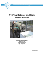
Northwest Marine Technology, Inc.
T13 Tag Detector and Gate
User’s Manual
Northwest Marine Technology
Shaw Island, WA
Phone: 360.468.3375
Fax: 360.468.3844
E-Mail: [email protected]
Web: www.nmt.us
August 25 2006
Table of Contents
Table of Contents................................................................ 2
Introduction ......................................................................... 3
1. Equipment Description.................................................. 4
T13 Detector .............................................................................................................. 5
Diverter Gate.............................................................................................................. 7
Dual Counter.............................................................................................................. 9
Control Box .............................................................................................................. 10
Fish Funnel .............................................................................................................. 11
Trailer....................................................................................................................... 12
Powering the Equipment.......................................................................................... 13
Power Supply 24V................................................................................................ 13
12V Batteries........................................................................................................ 14
Connectors and Plugs.............................................................................................. 15
Detection Standard .................................................................................................. 15
2. Equipment Setup and Testing .................................... 16
T13 Detector and Diverter Gate Setup .................................................................... 16
T13 Detector and Diverter Gate Testing .................................................................. 19
3. Equipment Operation................................................... 21
Getting Started......................................................................................................... 21
Initial Settings for T13 Tag Detector and Control Box, Table................................... 22
Tag Detection with Detection Standard ................................................................... 22
Control Box Operation ............................................................................................. 23
Menus: Navigation and Editing............................................................................ 23
Basic and Full Menus ........................................................................................... 26
Menus on Control Box, Table............................................................................... 27
Basic Tag Detector Menus ................................................................................... 28
Basic Control Box Menus ..................................................................................... 30
Full Menus............................................................................................................ 31
Full menus Tag Detector ...................................................................................... 32
Full menus Control Box ........................................................................................ 32
Radio Frequency Interference ................................................................................. 33
Magnetic Interference .............................................................................................. 33
4. Troubleshooting........................................................... 34
5. Maintenance ................................................................. 36
Care of the T13 Detector, Gate and Control Box..................................................... 36
Cleaning and Disinfection ........................................................................................ 36
Charging batteries.................................................................................................... 36
6.
7.
8.
9.
Service and Shipping................................................... 37
Equipment Specifications ........................................... 38
Contacting NMT............................................................ 39
Index.............................................................................. 40
T13 User’s Manual
Table of Contents
2
Introduction
The T13 is the largest of a new line of tunnel-type Coded Wire Tag (CWT) detectors. It
maintains the high sensitivity of the earlier R-Series detectors and their ability to detect a
tag in any orientation but accommodates a much larger fish.
T-Series detectors are designed to plug together with one or more other system
components such as a power supply, control box, and a diverter gate using a unified
system connector. Most components have two identical 8-pin connectors with identical
jumper cables to interconnect them.
The T13 detector’s tunnel is oval with the maximum inside dimensions of 7.5 inches
(19cm) by 13 inches (33 cm). It may be used with either the broad or the narrow
dimension upright, however the NMT (Northwest Marine Technology) funnel and gate
are designed for attaching to the detector when the larger dimension is horizontal.
For diverting fish, the T13 is supplied with a diverting gate, a control box and a dual
counter. The control box controls the settings for the gate, detector and control box
functions and records counts of detected tags in up to four different groups; for counting
untagged fish the dual counter is required. Using the control box it is possible to adjust
the system for a variety of situations, such as fish that move unusually fast or unusually
slow.
When using a gate, the gate and detector are powered with either the NMT 24VDC
power supply or with 24V from two standard 12V deep cycle batteries hooked in series.
Most T13s will be in permanent installations, but the detector may be mounted on a
small trailer allowing the detector to be moved around on site.
If you are interested in a different configuration of the T13 detector please contact
Northwest Marine Technology at 360-468-3375 for more information.
T13 User’s Manual
Introduction
3
1. Equipment Description
For permanent installation of the T13 detector and diverter gate the following equipment
and supplies are provided:
¾ T13 Detector
¾ T13 Gate
o 3 Amp Fast 250V cartridge fuse in electronics box
¾ Counter, modified R-Series
¾ T-Series Control Box
¾ T13 Fish Funnel
¾ 24 volt Northwest Marine Technology power supply with attached cables
¾ 2 12V deep cycle batteries with battery boxes
¾ 9 1/2’ counter cable
¾ 10’ jumper cable
¾ 15” jumper cable
¾ 10’ battery cable
¾ 2’ battery fuse cable
o 5 Amp Fast mini blade fuse
¾ One large battery box for storage
¾ Coded wire tag detection standard
¾ User’s Manual
Mobile detector and gate unit:
¾ All of the above equipment and supplies
¾ Trailer
¾ 2 large battery boxes for storage
¾ 4 stabilizing jacks for blocking up detector
The T13 detector is either installed in a permanent location or else is sold on a trailer.
Upon request and for an additional fee, Northwest Marine Technology will install the
detector to meet individual needs. If the detector is installed then there is very little set
up required by the user.
If the T13 is purchased with a trailer, it comes already installed on the trailer. The only
set up required is the adding of the accessory equipment.
T13 User’s Manual
Equipment Description
4
T13 Detector
Vents
Serial number
stamped on plate
Fish tunnel
Access plates
Fish tunnel support
brackets
Trailer, optional
Attachment plate
Figure 1- 1a: Front end of T13
Control Box
Dual counter
Fiberglass enclosure
Fish funnel and
bracket with hose
attachment
Figure 1- 1b: Front end of T13 with Fish Funnel, Counter and User
Interface
T13 User’s Manual
Equipment Description
5
Access plates
The T13 has two identical 8
pin connectors on the upper
rear access plate.
Fish tunnel
Vents
Fish tunnel support brackets
Drain
Attachment plate
Figure 1- 2: Rear end of T13
Take care not to damage the silicone seal between the tunnel and the fish tunnel
support brackets. Water inside the detector could cause damage. Contact NMT if
the seals are damaged so that water can enter the detector.
T13 User’s Manual
Equipment Description
6
Diverter Gate
The T13 diverter gate consists of two main parts: the beaks that hold the latching doors,
and the electronics box that has the connectors that power the gate and connect the
gate to the detector and that has the connectors for the cables from the solenoids that
drive the gate doors. The detector is mounted so that it is inclined, with water running
through the tunnel. As a fish hits an unlatched door it pushes it open and flows through.
Diverter gate
Gate electronics box
Serial number
Cables from batteries,
control box detector and
gate doors attach to the
gate electronics box
Gate door
cable
Door latch
Counter cable with
sensors in gate brackets
Gate doors
Figure 1- 3: Rear end of T13 with Diverter Gate
When there is power to the gate then the green LED is ON and the door for untagged
fish will be unlatched. Change the door that untagged fish come out of by switching the
cables from the solenoids.
On the right side of the gate electronics box there is a fuse holder with a 250V FAST
acting 3 Amp cartridge fuse. This fuse is to protect the circuitry in the detector and
control box if a short should occur in the gate electronics box. If the fuse blows, large
transient currents form the lead acid batteries may damage the control circuitry. Replace
the fuse and test the gate function. It is possible for the gate electronics box to receive
T13 User’s Manual
Equipment Description
7
power, but not have the doors function properly. If the gate electronics box does not
function properly, then remove it and return it to Northwest Marine Technology for repair.
2-pin Battery Cable Connector
Toggle switch
Battery On
Battery Off
8-pin connectors on detector
Green
Power
LED
8-pin connectors on gate
electronics box
2-pin connectors
for gate doors
Fuse
holder
Tagged
Untagged
Figure 1- 4: T13 Gate Electronics Box
T13 User’s Manual
Equipment Description
8
Dual Counter
A two-channel counter mounts on the front of the detector. Sensor probes that detect the
opening of the gate doors are mounted on the gate and are connected to the counter
with cables. The counter sensors are held in place with counter keeper springs. The
count for each gate door is continuously displayed, and can be manually increased (red
button) decreased (black button), or zeroed (black and red button pushed
simultaneously) with buttons on the counter box.
The counter display is continuously powered by a high capacity Lithium battery that has
a lifetime of more than 10 years with normal operation. When the battery is low, leading
zeros will appear in the display, for example "000427" instead of "427". The batteries will
last at least another week, perhaps a month after leading zeros first appear. When the
gate is not in use, the counter cable should either be unplugged from the back of the
counter, or else be sure to leave the counter sensors in their brackets with both gate
doors closed; otherwise the battery lifetime will be reduced. When a battery needs
replacement, the counter must be returned to NMT.
Dual counter modified for the T13 detector.
Counter cable with counter sensors and connector.
Back of dual counter showing box
connector and cable connector.
Serial number is under
connector
Brackets that attach to 3/8” bolts
on the front of the T13 detector.
Figure 1- 4: Dual Counter, front and back
T13 User’s Manual
Equipment Description
9
Control Box
Four line vacuum fluorescent display
Power on, LED is green
Buttons for navigating and editing
Buttons with LEDs for selecting
count group
Figure 1- 5a: Control box,
front.
Figure 1- 5b: Control box, back
Pressure plug
Serial number
8 pin connectors
Beeper with foam ear
protectors
With the T13 detector, the control box is primarily used to set the gain (detectors
sensitivity to tags), the approximate speed that the fish is traveling through the detector,
and the time when the gate opens and closes. Other functions are discussed further in
the Operations Section. The control box serves as the viewer and editor for the menus
for the T13 detector as well as for the control box itself. The control box can function as
a tag counter for up to four different groups of fish, and as a beeper indicating the
presence of a CWT. Once the gain, fish speed, and gate open and close times are set,
then the control box is not essential unless you want to hear the beeper and if you want
to view the bar graph for tag detection.
The face of the control box has a window with a four line vacuum fluorescent display. To
the right of the window are 4 white buttons for navigating and editing. Along the bottom
of the box are 4 black buttons with red LEDs in the center which select the count group.
The one with the red Led showing indicates the count group that is registering counts.
T13 User’s Manual
Equipment Description
10
At the top of the box in the center is a clear LED that lights red when a tag is detected.
To the right is another clear LED that lights green when there is power to the control box.
The back of the control box has two 8-pin system connectors for attaching a power
cable, a cable from the detector or a cable from the gate. The 5 digit serial number is on
the back below the connectors; it begins with “46”.
The beeper is also on the back of the control box. This beeper will sound when a tag is
detected and continue to beep for as long as there is a tag in the detection area or for as
long as the gate is open. If the alarm is too loud for the conditions in which you are
working, the center hole of the beeper may be partially or completely covered with a
piece of tape or plugged with two foam ear protectors.
Fish Funnel
The fish funnel attaches to the front of the detector and helps guide fish into the tunnel. It
also provides a way to inject water to help lubricate the tunnel. The water source can be
an ordinary garden hose connected to the fitting provided at the bottom of the funnel
support structure. A valve is provided to regulate the water flow. When the valve is
properly adjusted, streams of water will emerge from tubes at the sides of the funnel.
Fish funnel with
bracket
Water outlets
Figure 1- 6: Fish Funnel attached to front of T13
detector
T13 User’s Manual
Equipment Description
11
Trailer
Bracket for
stabilizing detector
Trailer
Jack for adjusting
angle of detector
2 12V batteries
and boxes
Figure 1- 7a: T13 detector with Diverter Gate and funnel on trailer
Removable handle
for moving trailer
Figure 1- 7b: T13 detector on trailer
showing removable handle
In photo 1-3a the trailer is supported on blocks. In place of blocks, newer models have
jacks that are used to lift the weight of the trailer off of the tires. Without the stabilizing
jacks, the motion of the detector when a large fish goes through it, or when it is bumped,
may cause a false detection. The newer trailers also have two large boxes at the rear of
the trailer for storage of the jacks, cables and other supplies.
The T13 detector should be set up away from equipment that generates strong magnetic
fields such as large motors. Strong magnetic fields may cause false positive detections.
If this happens, move the detector further away from the source of the magnetic field.
The trailer is not designed for towing by a motor vehicle.
T13 User’s Manual
Equipment Description
12
Powering the Equipment
The T13 detector, gate and control box, when used together, may be powered by either
the NMT 24VDC power supply or by two 12V batteries that are connected in series to
produce 24V. Use either one, but do not use both the power supply and the batteries at
the same time.
DO NOT USE BOTH THE POWER SUPPLY AND THE BATTERIES
AT THE SAME TIME.
Power Supply 24V
The 24VDC power supply may be used to power the T13 detector as well as the
detector with a gate and control box. It will function from an input ranging from 100250VAC. The cord with the three pronged plug is glued into the power supply. Do not
attempt to remove it.
Plug that attaches to 8 pin connector on either
the detector, gate or control box
Cable from
power supply to
outlet
Glued plug
DO NOT REMOVE
Figure 1- 8: Power supply with cords.
The power supply must be kept out of the water.
If you are using the 24V power supply, plug the cable with the 8 socket plug into the
eight pin connector on the rear of the detector, gate electronics box or the control box.
Plug the cable with the three prong connector into a wall outlet or an extension cord.
T13 User’s Manual
Equipment Description
13
12V Batteries
The gate electronics box has a connector for the battery cable that comes from the 2
12V batteries that are connected in series. The power goes first to the gate electronics
box and if the gate is connected to the T13 detector and/or the control box, they will also
be powered.
The battery cable has two leads, one black and one white, each with a fork terminal on
the end. The one on the white wire and with red tape will attach under the thumb screw
on the positive terminal on one battery and the black wire will attach to the negative
terminal on the other battery.
In order to connect the two batteries in series to produce 24V, a shorter green and white
cable, the battery fuse cable, is provided; it has a fuse holder in the middle. The green
wire connects to the unused negative terminal of one battery and the white wire attaches
to the positive terminal of the other battery.
The 5 AMP fast acting mini blade fuse will blow if the battery cables are shorted. If this
should happen, check the fuse; if the “S” shaped wire is broken, then change it. Extra
fuses have been supplied in the large storage box.
Battery cable with
one lead (white
wire) attaching to
+ of one battery
and – lead (black
wire)of the other.
Battery fuse cable
with mini blade fast 5
amp fuse.
Fuse
The long black
battery cable is
attached to one
of the battery
boxes.
Figure 1- 9: 2 12V deep cycle batteries connected in series
Keep the lids on the battery boxes at all times to avoid damage to the batteries.
T13 User’s Manual
Equipment Description
14
Connectors and Plugs
On the rear of the detector, the control box and the top of the gate electronics box, there
two 8-pin connectors which are all identical. These connectors are interconnected using
jumper cables which have two identical ends, so it doesn’t matter which cable end gets
attached to which 8-pin connector as long as the units are hooked together in a chain.
The gate electronics box has three additional connectors: two 2-pin connectors on the
lower front that are identical and accommodate the plugs on the gate door cables, and a
larger 2-pin connector on the side that is for the battery cable.
If a connector is not in use then the dust cover should be closed over it for protection
against dirt and water.
8 pin connector with
dust cover open
Locking ring
8 pin connector with
dust cover closed
Figure 1- 10: 8-pin connectors with dust
covers and jumper cable with 8 socket plugs.
Jumper cable with two 8socket plugs with locking
rings. The cable ends
are identical.
Detection Standard
The detection standard is an aluminum rod which has a standard length CWT imbedded
in a wooden block at one end. Pass the detection standard through the tunnel to verify
that the detector is detecting tags and to determine the range of speeds at which a tag is
detected.
Block with standard
length coded wire tag
Figure 1- 11: 6 Foot Aluminum Detection Standard
T13 User’s Manual
Equipment Description
15
2. Equipment Setup and Testing
T13 Detector and Diverter Gate Setup
1. If not already attached, add the dual counter to the top left edge of the detector
and the control box to the front right edge. Leave the first nut next to the detector
flange in place, add the device and then screw on a second 3/8” nut to secure
the device in place.
3/8” nuts and 3 “ 3/8-16 bolts hold dual
counter and control box to detector
Long jumper cable
attached to back of
control box
Counter cable
Figure 2- 1: Dual Counter and Control Box in place on front of detector
2. Connect the long jumper cable between one of the connectors on the control box
to an 8-pin connector on the rear of the detector (this could also go to one of the
8-pin connectors on the gate electronics box).
3. Attach the short jumper cable between a free 8-pin connector on the detector and
an 8-pin connector on the gate electronics box.
4. Attach the two gate door cables to the 2-pin connectors on the gate box. The
connector that is labeled “Tagged” is for the gate door that you want the tagged
fish to come out. “Untagged” is the door you want the untagged fish to come out.
5. Attach the counter cable to the back of the counter. Put the counter sensor
probes in the holders on the gate with the springs. Open one of the gate doors
several times and see which side of the counter counts. Verify that the right
counter is changing when the right door is opened. If not then switch the probes.
6. Clear the counters by pushing both the black and red buttons at the same time
under each display.
7. Battery power to the gate and detector:
a. If you are using the two 12V batteries to supply power to the gate
and detector be sure that the NMT24V power supply is not
T13 User’s Manual
Equipment Setup and Testing
16
b.
c.
d.
e.
f.
connected and proceed with the items below; otherwise skip to item
8.
The battery cable wires are attached to the battery terminals with the
thumb screws. Black insulated fork (black wire) to (–) post on one battery,
and red insulated fork (white wire) to (+) post on other battery.
Be sure that the battery fusel cable has a 5 AMP fast acting mini blade
fuse in the holder and attach it to the other two battery posts. The Black
insulated fork (green wire) to the (-) post on the battery that already has
the (+) post occupied, and the red insulated fork (white wire) to the (+)
post of the other battery.
Attach the connector end of the battery cable to the connector labeled
”Battery Cable” on the side of the gate electronics box.
Push the toggle on the switch to the “Battery On” position. The green LED
on the gate box will come on.
The toggle switch on the gate electronics box only affects power from the
batteries, not the NMT 24V power supply.
Counter cable
NMT 24V power supply
would be connected here if
NOT using batteries
Long jumper cable
from control box to
gate electronics
box (or detector)
Short jumper cable
between gate electronics
box and detector
Battery cable
attached to gate
electronics box as
long as not using
NMT 24V power
supply).
Cables from gate doors
Gate doors
Counter sensor probes in door brackets
Figure 2- 2: Cable hook on gate electronics box and detector
8. NMT 24V Power Supply to the gate and detector:
a. If you are using the NMT 24V power supply to operate the detector
and gate be sure that the battery cable is disconnected, and proceed
to the items below; otherwise skip to item 9.
b. As long as the gate box is attached to the detector and the control box is
attached either to the detector or the gate box, then the NMT 24V power
supply may be connected to an 8-pin connector on either the gate
electronics box, or the detector or the control box.
T13 User’s Manual
Equipment Setup and Testing
17
c. Plug the other cable on the NMT24V power supply into a wall outlet; the
power will be on and the green LED on the gate electronics box will be
on.
9. In order to protect the connectors from water, be sure that all connectors that are
not in use are covered with their dust caps.
10. If not using a trailer then skip to step 14.
11. If the T13 is on a trailer, raise and mount the detector as follows:
a. Unscrew the 2 nuts (if they are present) next to the jack that secure the
detector to the trailer frame.
b. Use the lifting jack under the funnel to raise the detector.
c. Screw the bottom right and left screws in the sway bracket to the trailer
frame.
Screws for securing
detector to trailer
Holes for screwing
sway bracket
when detector is in
raised position
Sway bracket
Jack
Screws that go into
holes for stabilizing
detector
Figure 2- 3: Jack in lowered position
12. Mount the stabilizing jacks as follows:
a. Remove the 4 stabilizing jacks from the storage box on the trailer.
b. Set a jack under each jack support near the tires.
c. Lift the trailer one end at a time moving back and forth between the two
jacks. The tires DO NOT lift off the ground. The jacks are to take some of
the weight off the tires to keep the detector from bouncing on the tires.
T13 User’s Manual
Equipment Setup and Testing
18
Towing handle
removed
Figure 2- 4: Stabilizing jacks supporting gate end
of trailer
13. Remove the towing handle.
14. Attach a hose to the hose connector on the funnel bracket.
a. When set up is complete, adjust the water flow so that the tunnel is well
lubricated and the fish move easily through the detector and gate.
T13 Detector and Diverter Gate Testing
If you have followed the steps in Setup, there should be power to the gate, detector and
control box. The following steps will verify if there is power and troubleshoot many
problems.
1. Check that the gate has power.
a. If there is power to the gate electronics box then the green LED will be
ON and the door that has its cable connected to the connector labeled
“Untagged” will be unlatched.
b. If there is no power then:
i. If using the 2-12V batteries and there is no power then check the
following:
1. 12V batteries are connected together with the battery fuse
cable
2. the battery cable wires are attached to each battery
3. the fuse in the battery fuse cable is good. Change if
necessary
4. the battery cable is properly plugged into the gate
electronics box
5. the battery toggle switch is in the “Battery ON” position
6. batteries are charged
ii. If using NMT 24V power supply and there is no power then check
the following:
1. Verify that the 8-pin connector on the power supply is
correctly attached to the gate electronics box or the
detector.
T13 User’s Manual
Equipment Setup and Testing
19
2. the short jumper cable is attached between the gate
electronics box and the detector
3. the power supply is plugged into a functional wall outlet
2. Check that the control box and detector are getting power.
a. If the control box is getting power the green LED on the front panel will be
ON and a menu will be visible in its display window.
b. If both the control box and the detector are getting power than the menu
that will be visible is that for Tag Detector.
i. Run the detection standard through the middle of the tunnel, if the
beeper goes off, then the detector has power.
c. If the control box is getting power, but not the tag detector then the menu
on the control box display will say Control Box.
i. Check the cable connections between the detector, gate and
control box.
ii. On the control box attempt to move to the Tag Detector menu
(see next section for navigating between devices). If you do not
see a menu for the Tag Detector, then the detector is still not
getting power. Verify by running the detection standard through
the tunnel; neither the beeper will go off when the tag goes
through if there is no power to the detector nor will the gate latch
and unlatch.
d. If the detector is getting power, but not the control box, the display and
green LED on the control box will not be visible.
i. Run the detection standard through the tunnel. The gate will latch
and unlatch if the detector has power and the gate and detector
are connected.
ii. Check the cable connections between the detector, control box,
gate and power source.
If you have power to the equipment then you are ready to start operation. If there is still
no power then call Northwest Marine Technology 360-468-3375 for assistance.
T13 User’s Manual
Equipment Setup and Testing
20
3. Equipment Operation
Getting Started
Once power is connected to the detector it takes about 20 seconds before the
detector will detect a tag and sound the beeper.
The T13 detector and control box have certain settings that have been set at the factory
and which can not be changed, other settings, though set at the factory, may be
changed by the user to fine tune the equipment to their specific needs. Adjusting menu
settings in the control box allows for these changes.
The initial control box menu settings that may be changed, but are put in at the factory
are listed in the table below “Initial Settings for T13 Tag Detector and Control Box”. A
card with these settings is attached to the detector for easy reference. Begin by using
these settings for testing the equipment with your fish. They may be adjusted later if
necessary by following the directions given later in this section.
The issues you need to think about when putting fish through the T13 detector and gate
are the Fish Speed setting as entered on the Tag Detector menu, the actual fish speed
and fish spacing.
1. Fish Speed setting: The Fish Speed setting on the Tag Detector menu sets
the center of the range of actual fish speeds for which the T13 detector will most
reliably detect CWTs. Actual fish speeds that are anywhere from about 1/2 to 2
times the Fish Speed setting will be detected with equally good reliability;
outside this speed range, the tag signal strength and therefore detection
reliability drops off.
2. Actual fish speed: The actual fish speed can be affected by the angle of the
detector and the rate of water flow through the funnel and detector tunnel and
how the fish are entered into the funnel. For the T13 detectors the angle has
been predetermined. (These values were initially set at the factory). If you put
well spaced tagged fish through the detector and there is only one tag detection
then the water flow is adequate. If fish get caught up or move too slowly then
two counts may occur. Either adjust the water flow or set the Fish Speed setting
slower. If your Fish Speed setting on the Tag Detector menu is set too high for
the actual fish speed your fish are going through the detector you may get
double counts, so it is better to set the Fish Speed setting to a lower value and
have your fish move faster. However, if your Fish Speed setting is set too low
and you have fast moving fish or fish that are very close together, then the tag
may not be detected.
a. Establish good water flow. Set the Fish Speed setting on the Tag
Detector menu to 1 m/s, and Gain at 45.
3. Fish spacing: It is important that one fish is through the detection region of the
detector before the next fish enters the detection region. If the Gate Open is set
at “0”, the gate will begin to open as soon as the detector registers a tag. The
length of time the gate stays open is determined by the Gate Close time. If the
gate opens too soon then the fish in front of the one just detected may be
T13 User’s Manual
Equipment Operation
21
misdiverted. If the gate door stays open too long, then the fish coming after the
one that was just detected may be misdiverted. If the gate door doesn’t stay
open long enough or opens too late, then the fish being detected may be
misdiverted.
a. Using the suggested settings put fish through the detector and watch that
they get through the gate with plenty of clearance. Look down the tunnel
as you feed fish into the funnel and see how they clear the gate door. If
you feed fish into the funnel quickly, you may need to shorten the Gate
Close time from .5 sec to .3 or .4 sec.
Initial Settings for T13 Tag Detector and Control
Box, Table
Initial Settings for T13 Tag Detector and Control Box
<Tag Detector>
<Operation>
<Setup>
Gate Open (sec)
0.0
Gain
Gate Close (sec)
45
0.5
Det Mode
precise
Fish Speed (m/s)
1.0
<Control Box>
<Group 1>
<Setup>
Tag Count
0 Count in Group
Beeper
Menu Style
Fish Counts
1
ON
Basic
N/A
Enter underlined values for initial setup
Gate Open = Time from when tag detected to when gate opens
Gate Close = Time from when gate opens to when gate closes
A full explanation of how to navigate these menus follows. If these settings work well for
you, then you do not need to do any changes to the menu settings
Tag Detection with Detection Standard
The ability of the T13 to detect a CWT is dependant upon the speed that the fish is
traveling through the tunnel. If the fish are moving slower than the Fish Speed setting
entered in the Tag Detector Setup menu, than the tag may be detected twice; if the fish
are moving too fast for the Fish Speed setting, then the tag may not be detected. For this
reason a detection standard (a pole with a standard length coded wire tag embedded in
one end) is supplied with the detector. Move the detection standard in and out of the
tunnel at the speed the fish will be traveling in order to get an idea of how to set the Fish
Speed setting in order to get a proper detection.
Confirm this speed by putting some test fish through the detector. Be sure the water is
on and adjust the water flow and Fish Speed setting so that the beeper always goes off
when a tagged fish goes through the center of the tunnel.
T13 User’s Manual
Equipment Operation
22
Control Box Operation
When the control box is receiving power the green LED will be lit, and the Tag Detector
menu will be visible on the display. The control box displays the menus for the detector
and control box. The control box can tally tag counts for up to 4 groups.
The control box beeper is very loud: In a quiet environment you may wish to cover it with
several layers of tape or insert foam ear plugs into the hole. The beeper sounds when a
tag, or other moving object that has a magnetic field, passes through the detection
range. It will beep for as long as the gate is open.
When power is first applied to the control box the words “NMT T SYSTEM” appear
briefly on the display. If the detector, gate, and control box are all hooked up, then the
Tag Detector Operation menu appears next. If the control box is powered without being
connected to the detector, then the control box operation menu will be seen on the
display.
The detector and control box each has its own set of three menus: Properties,
Operation and Setup. The Operation menu is the first menu displayed for each unit. After
setting the gain on the Tag Detector Operation menu, and the fish speed and Gate open
and close times on the Tag Detector Setup menu, you will most likely want to have the
Operation menu for the control box visible while detecting tags and recording counts.
Pass the end of detection standard through the tunnel to determine the best gain setting
on the Tag Detector Operation menu. The maximum of the signal bar graph should be
about half way to the vertical Tag Detection threshold line when a tag is not present.
Threshold line, when bar goes above this line a
tag has been detected.
The signal bar will flicker back and
forth. Its maximum excursion should
be about half way to the threshold line
when a tag is not present.
Figure 3 - 1: Signal Bar Graph
and Threshold
Signal bar graph
Menus: Navigation and Editing
There are a few rules for navigating and editing menus. Once learned it is very easy to
move and change values on the various menus. We recommend experimenting with a
control box that is hooked to a gate and detector while reading the rules below.
T13 User’s Manual
Equipment Operation
23
A cursor in the form of an underline is always present somewhere in the display.
Cursor
Figure 3 - 2: Cursors
A line of the display consists of a caption at the left of the line and a value field at the
right. Exceptions include caption only lines, and the signal bar graph.
Caption: Tag
Detector
Value Field: 1
and 48
Signal Bar Graph
Figure 3 - 3: Caption and Value Field
Caption only line:
Operation
The up and down buttons will move the underline cursor from line to line up or
down in the display. Moving the cursor past the top or bottom of the display will scroll the
whole menu up or down if there is more menu to be seen beyond what is visible in the
window.
The first line on the menu displays the name of a system unit with arrow heads at
each end < >. Scrolling left or right will select different units. The second line displays
the menu for each system unit, also with arrow heads at each end < >. Scrolling left or
right here selects different menus for the same unit.
T13 User’s Manual
Equipment Operation
24
< arrow heads: scroll left,
>arrow heads: scroll right
Up and Down
buttons
Right and Left
buttons
Tag detection
threshold
Buttons for
selecting
active count
group
Figure 3 - 4: Arrow heads and Buttons
If there are no arrow heads, then the whole line including the caption will be
underlined, indicating an information-only line.
Information only line: no arrows
and both caption and value field
are underlined
Figure 3 - 5: Information only line
When only the value field is underlined then the underlined portion is editable. If the item
is editable, then the left and right buttons will select a digit within the editable field, and
once selected the up and down buttons will increase or decrease that digit. Moving the
cursor off either end of the editable field will end the editing session.
Value field underlined: this
number (48) is editable
Digit selected, ready to be edited
Figure 3 - 6: Editable value fields
1. Practice moving from menu to menu and changing values before you set up to
count tags.
2. Before leaving a menu, return to the original options that were set at the factory.
Refer to “Initial Settings for T13 Tag Detector and Control Box” chart in this
section as well as the “Menus on Control Box” sheet which is also in this
section.
T13 User’s Manual
Equipment Operation
25
Basic and Full Menus
For most applications the menus on the control box may be set up as described on the
“Initial Settings for T13 Tag Detector and Control Box” chart. Gate timing is set in the
Tag Detector menus; minor adjustment in gate timing may be required.
This section is a more detailed explanation of the various menus, definitions of terms,
applications and navigation between units and menus.
For reference refer to the table on the next page titled “Menus on Control Box”. Green
represents the Tag Detector and purple is the Control Box. Each unit has three menus,
and moving between the menus is represented with the blue arrow (white for moving in
control box between the count groups).
The suggested settings for each unit are listed under Default, the other possible settings
are listed under “Alternate”.
If you look at the table “Menus on Control Box”, you will see that most menus are in
black, but a few lines are in purple. All of the black represents the basic menu. If the
menu style is set to basic then only those items in black will be visible on the display. If
the menu style is set to full, then everything in black as well as purple is visible on the
display. The full menu is only needed when you have more than one detector hooked
together. However, the settings in the full menu can affect how the equipment works,
even if you are operating only a single unit, the settings on the full menu should be left at
the defaults shown in the table “Menus on Control Box” unless you are instructed to do
otherwise.
Do not change the Full Menu settings unless instructed to do so.
The Basic Menus for all units will be discussed first and then the Full menus.
Basic Menu
selected
Figure 3 - 7: Menus Style, Basic
T13 User’s Manual
Equipment Operation
26
Menus on Control Box
Control Box
Tag Detector
Properties
Caption
Serial Number
HW version
FW Version
S.Length (mm)
Factory Set
13###
#
##
12
Tag Detector
Caption
Default
Gain
45
Control Box
Properties
Caption
Serial Number
HW version
FW Version
Supply volts
Factory Set
46###
#
##
24
Control Box
1
Operation
Alternate
Caption
Gate Open (sec)
Gate Close (sec)
Det. Mode:
Fish Speed (m/s)
Typical 1m/s
ID of this unit
Tag Det
1-200
Default
0.0
0.5
Precise
1.0
Alternate
0.0 - 6.5
0.0 - 6.5
Early
0.2 - 3.0
1
Tag Detector
1
Group 1: name
Caption
Tag count
Fish count
Edit name:
Setup
Default
0
N/A
XXXXX
Group 2,3,4: name
Caption
Tag count
Fish count
Edit name:
Default
0
N/A
XXXX
Scrolling between Units
Scrolling between menus within a Unit
Black is Basic menu style
Purple is Full menu style
Words in Italics are not seen on display
Setup
Caption
*Clear All Counts*
Count in Group
Beeper
Menu Style
Fish Counts
ID of this unit
Control Box
View
Inputs to counter:
Tag Det ID
Fish Det ID
Switch ID
Default
Alternate
1
On
Basic
N/A
2,3,4
Off
Full
show
1
Normal
Subnet
0
0
0
Menus on Control Box, Table
T13 User’s Manual
Equipment Operation
27
Basic Tag Detector Menus
When the Tag Detector menu appears, there is a number to the right on the same line
as the words “Tag Detector”. The number is the unit ID (identification) number, in this
case <Tag Detector 1>; both the caption and the number “1” are underlined in a
continuous line, so the unit ID number may not be changed from this menu. The factory
setting is 1. <Tag Detector 1> is at the top line in all three of the tag detector menus.
On the second line of the display, the cursor can be scrolled left or right between the
three tag detector menus: Operation, Properties and Setup.
1. <Operation>: When the Tag Detector Operation menu appears there is a solid
line across the display under <Operation>. The “<>” arrows indicate that you
can scroll left or right from the <Operation> menu to either the <Properties> or
the <Setup> menu.
a. Signal Bar Graph, Gain: With the solid line under <Operation>,scroll
down one line so that the solid line moves under the bar graph across the
display. This is a visual setting for “Gain”. The “Gain” is the setting for the
tag detector’s sensitivity to magnetic disturbance. The detectors are
designed to exclude all magnetic fields except those created by an object
going through the detector. However, some stray magnetic fields do get
into the detector and this is referred to as background noise. The
fluctuating bar on the left is the magnetic noise at the numerical gain
setting indicated on the next line down. The vertical line in the center
marks the detection “Threshold”. When the magnetic disturbance is large
enough, the bar goes above threshold and the detector beeps.
i. The bar graph is the one exception when a cursor under the entire
line allows editing. The gain value may be changed by either
changing the length of the bar or by changing the numerical value
in the line below. To edit gain from the bar graph, push the right
button to increase the gain or the left button to decrease it. You
will see the numerical value will change with each push of the
button, and the length of the bar will either increase or decrease.
ii. Set the gain so that the background noise, or bar, is between 1/3
and ½ way to the threshold mark. In a fairly quiet environment this
is at about 48. Verify the setting using the detection standard.
b. Gain, Number: Push the down button again, now only the displayed
number is underlined. The length of the line is three digits. To edit this
value, push either the right or left button; the underline will change to a
shorter line that is the width of a singe digit. Keep pressing the button until
the line is under the number you want to change. Push the up button to
increase the number, push the down button to decrease the number. If
you set the gain too high, then the bar on the graph will go above
threshold and the beeper will sound continuously. When you have the
number you want, push either the right or left button until the single digit
cursor goes off the end of the filed and broadens to an underline three
digits wide under the entire number, now you can push the upper button
and move the underline to a different part of the menu.
T13 User’s Manual
Equipment Operation
28
2. <Properties>: There is a solid line across the display under <Properties>, but
by pushing the right or left button you may scroll to a different menu,
<Operation> or <Setup>. None of the items on the Properties menu may be
changed. This is indicated by the full width underline when you scroll down to
any item. This menu gives information about this detector; all values are set at
the factory.
a. Serial Number: The serial number is unique to this detector. The serial
numbers for the T13 Tag Detector begin at 13001.
b. HW Version: This represents the hardware version of the detector.
c. FW Version: This is the version number of the software for the
electronics in the tag detector.
3. <Setup Menu >: <Tag Detector 1> will be the top line as described under the
operations menu. With the solid underline under “Properties” push the left
button once or the right button twice and move to the Setup menu. Two of the
gate settings are on this menu since the time that the gate opens and closes is
dependant on the signal being sent from the detector to the gate.
a. Gate Open (sec): Scroll down to this line. Gate open is the elapsed time
from when the tag is detected to when the gate opens. The time value is
set on the right. For most circumstances settings to tenths of seconds is
adequate. For the gate to begin opening as soon as a tag is detected set
it to 0.00.
b. Gate Close (sec): Scroll down and edit the numbers as before. Gate
close is the time from when the gate opens until it begins to close. This is
set long enough so that the largest fish can get through before the gate
closes, but short enough so that the gate is completely closed before the
next fish has reached the front edge of the gate flapper.
c. Det. Mode: Detector Mode is the setting which determines when the tag
is registered by the detector. There are two options; Early and Precise.
i. With Early detection, the tag is detected early in the tunnel and
the signal is sent to the gate before the tag reaches the center of
the tunnel. If your fish is moving too slowly through the tunnel in
this mode, the detector will beep twice. This mode is used when
you have long fish going in tail first. The tag must be detected and
the gate opened before the tail of the fish reaches the flapper.
ii. In Precise mode the tag is detected near the center of the tunnel,
and is a short distance past center before the detection is
confirmed and a signal can be sent to the gate. In this mode, a
very fast moving fish may reach the gate before it has time to
open, but closely spaced fish moving at moderate speed can be
more readily separated. Precise is the suggested detection mode.
iii. When you scroll down to Det. Mode the entire word “Early, or
Precise” is underlined. To edit from Precise to Early, push either
the right or left button. The cursor becomes a single line under the
last letter (e); push the up button once to go to Early. Push the left
or right button again to underline the entire word; this sets the
word in memory. To go from Early to Precise, the method is the
same, except that the cursor is only under the “y” in Early (y);
push the down button to go to Precise.
T13 User’s Manual
Equipment Operation
29
4. Fish Speed (m/s): Fish speed is defined as the speed in meters per second
(m/s) with which the fish are going through the tunnel. The speed depends on
the angle of the detector and on how much water is going through the tunnel
with the fish. Scroll down to the caption Fish Speed (m/s).The cursor is under
the number at the right. This number on the first line is all that can be changed.
The “Typical 1 m/s” is for reference and is the suggested setting. The fish speed
may be set to tenths of a m/s from 0.2 to 3.0 m/s, but 1 m/s is a good starting
point and will work well in most non-critical situations where the actual fish
speed is not well known or well controlled. Edit the fish speed in the manner
described above. Using the up button scroll back to the top of the menu until
“Tag Detector” is underlined. Scroll right to Gate or left to Control Box.
Basic Control Box Menus
As with all menus, the name of the unit and its ID number is the first line, <Control Box
1>. From that line you can move right or left to the Tag Detector menu.
1. <Group 1> (2,3,4): In reality these are four operation menus, but due to limited
space the line that says <Operation>is not present. The control box can keep
track of tag counts for 4 different groups of fish. Each group can be accessed by
either pushing the appropriate LED button at the bottom of the control box or by
scrolling through the Groups with the right navigation button. After group 4 you
will go to the Setup menu and if you scroll right again you will be at the properties
menu. Note that if the light is on in Group 1, but you scroll to Group 2, you are
still counting in Group 1 and viewing the information for Group 2.The menus and
editing for each count group is the same, so it will only be discussed for Group 1.
In each group menu there are the following:
a. Tag Count: The editable value field of this line represents the number of
tags that have been counted for this group of fish. An easy way to clear
the count to “0” is to push and hold the right and left buttons at the same
time. Edit the number works as before; push the right or left button until
the cursor is under the number you want to change and then push the up
or down button to increase or decrease the count. Push the right or left
button to get the cursor under the entire number and then scroll down.
b. Fish Count: At this time fish count is not available (N/A). In the future we
hope to have a fish counter that can be attached to the system to count
the total number of fish that have gone through the detector.
c. Edit Name: This line is below Fish Count, and is normally not visible, but
you can scroll down to it. By entering a name in this line’s value field, you
change the corresponding field of the Group caption line, so you can label
each group with your own choice of group name.
i. Editing the alphanumeric field works much like editing a numberyou use left-right keys to select a digit position and up-down keys
to alter it. The difference here is that the choices include not only
numerals but also capital and small letters. The up key steps
through the capital letters A..Z, then the small letters a..z, then the
digits 0…9. The down key steps through the sequence the other
way. Choosing each letter in turn you can build up a group name
of up to ten characters, such as “Male Coho”. When done, step
T13 User’s Manual
Equipment Operation
30
the cursor off one edge of the field to get the cursor below the
whole name, and then step up or down to another line.
ii. To delete a name, go to the edit name line and press the right and
left buttons simultaneously.
iii. Scroll using the right button through groups 2,3,4 to <Setup>.
2. Setup Menu: From <Setup> you can scroll right or left to Properties menu or
Group 4 menu.
a. *Clear All Counts*: Move the cursor to this line. By pressing the right
and left buttons simultaneously the counts are cleared in all four of the
groups at the same time, keep holding the buttons until “OK” appears.
Release.
b. Count In Group: This is another way of setting the group you want to
count in. You can select the group from the LED buttons at the bottom of
the control box or you can edit this number to the group you want to count
in. If you change the group with the button at the bottom you will see the
number change here. If you want to use the tunnel as a detector only and
not count in any group you may set the count group to “0”, and no counts
will be recorded.
c. Beeper: Scroll down to beeper. There are two choices, ON and OFF.
The beeper should be ON unless you have a specific reason for it to be
off. Without the beeper your only sign that a tag has been detected is the
red LED on the front of the control box with light up and if you are on the
Tag Detector operations menu, the bar will go above threshold, or if you
are looking at the counts in a selected count group the tag count will
increase.
d. Menu Style: This should be set at basic unless you are told to do
otherwise. To change to Full, push the right button so that the line is
under the “c”, push the up button. To change back to Basic push the
lower button. To set, push the right or left button until the word is fully
underlined.
e. Fish Counts: This is here in anticipation of a unit that will count total
number of fish that go through the detector. N/A means that this unit is
not available. If such a unit becomes available, then the N/A would be
switched to Show, and the fish count would show on the Group menu.
i. Scroll back up to the <Setup> line and push the right button.
3. Properties Menu: From <Properties> you can scroll right to <Group 1>, or left
to <Setup>. As with the other units, the properties menu is informational. All of
the values except for Voltage are set at the factory.
a. Serial Number: the serial number for Control Boxes begins at 46000.
b. HW Version: Hardware version, set at factory.
c. FW Version: Firmware version, set at factory
d. Supply (Volts): This reads the voltage of the power supply or the
battery, whichever is being used. This is a good place to check battery
voltage to see if it needs charging. When the cursor is here, it will flicker
as the voltage changes and is updated.
Full Menus
Full menu items are in purple in the “Menus on Control Box” table. They are only visible
when the Menu Style in the Control Box Setup menu has been set to Full. These values
T13 User’s Manual
Equipment Operation
31
should be set as to the values listed in the table unless it is specifically indicated
otherwise.
Full menus Tag Detector
1. Properties menu:
a. S. Length (mm) 41. This is Sample Length and is a number particular
to the T13 detector. It is there for reference purposes.
2. Setup menu:
a. ID of this unit Tag Det 1. This is where the ID number that you see at
the top of the Tag Detector menus is set. If another detector were
attached to the system, this line would be used to set its ID number to 2
so that the two units could be distinguished. It is possible, from the same
Control Box to view the menus of two or more detectors hooked up
together, but only after the unit numbers have been set to be distinct. As
a result, the address of one must be changed before the second one is
connected. If two indistinguishable units are connected, the control box
will complain when asked to access either one of them.
Full menus Control Box
1. Setup menu:
a. Menu Style: There are two options Basic and Full. Normally the choice
is Basic, but as described in this section there are occasions when the
Full menu is required.
a. ID of this unit Control Box 1: As with the other units, if there is more
than one control box hooked into a system, then each must have its own
ID number. When there is only one control box its ID number would be
1.
b. View: There are two options, Normal and Subnet. For most purposes
you would use Normal. In this view as you scroll from one unit to another
in the system you go from tag detector to gate to control box. If you have
two tag detectors and gates, then you would scroll through tag detector
1, gate 1, control box 1 then tag detector 2, gate 2, control box 2 etc. If
you want to see the tag detectors grouped together choose Subnet, then
you would scroll tag detector 1, tag detector 2; gate 1, gate 2, then
control box 1, control box 2.
c. Inputs to counter: These are the units that are hooked up in the
system that relay active information to the counter.
I. Tag Det ID: If this is set at “0” then all tag detector signals
from all detectors hooked up in the system will be counted. If
it has a number other than ‘0’ then only a detector with that
particular ID number will have its tag counts registered on
the counter in the control box.
II. Fish Det ID: At present there is no fish detector, but when
there is, it will work like the tag detector. If a “0” is chosen
then all fish passing through all fish counters would be
counted, otherwise only fish passing through the fish
detector with the given ID number would be counted.
T13 User’s Manual
Equipment Operation
32
III. Switch ID: This is designed to accommodate a foot switch
for moving between count groups. It would operate much as
the lighted buttons do.
Radio Frequency Interference
The T13 tag detector has been designed to withstand radio frequency interference from
hand held radio transmitters and cell phones kept at a moderate distance from the units.
However if a radio transmitter is operated too close to the detector (several feet) it may
set off the detector and give false positive detections.
Magnetic Interference
The T13 detector should be set up away from equipment that generates strong magnetic
fields such as large motors because these magnetic fields may cause false positive
detections. If this happens, move the detector further away from the source of the
magnetic field.
T13 User’s Manual
Equipment Operation
33
4. Troubleshooting
TROUBLESHOOTING SUMMARY TABLE
PROBLEM
POSSIBLE CAUSES
SOLUTION
Beeper doesn’t sound when
detection standard is run
through tunnel
1. Haven’t waited long
enough after hookup of
power for electronics to
warm up.
1. Wait 15 – 20 seconds
after hookup before
attempting a tag detection.
2. Plug from power or
control box is not properly
tightened to connector.
3. Battery may be low or
dead.
4. Fish speed is not set
correctly
Beeper is going off without
a tag being present
1. Detector may be too
close to equipment that is
generating a strong
magnetic field.
2. A hand held radio, cell
phone or other piece of
equipment generating radio
frequency interference may
be too close to the detector.
3. The gain may be set too
high.
Fish are not diverted
correctly
1. Fish are not spaced far
enough apart.
2. Gate close time may be
too long.
2. Check that plugs are
tight. Push on plug and
tighten ring.
3. Charge battery with
battery charger.
4. Set fish speed to 1m/s
and check with detection
standard.
1. Move detector away
from equipment
2. Move the radio
frequency generating
equipment further away
from the detector.
3. Check the Tag Detector
menu on the control box,
the gain should be at about
45; lower in a magnetically
noisy environment.
1. Fish should go through
detector one at a time with
enough space between so
that one has gone through
the center of the tunnel
before the next is entered.
2. The gate may be staying
T13 User’s Manual
Troubleshooting
34
open too long, shorten the
gate close time.
The counter counts 2 tags
when only one tagged fish
has gone through
1. The fish is not moving
fast enough through the
tunnel for the set fish
speed.
1. a. On the Tag Detector
setup menu set the Fish
Speed to 1m/s.
b. Make sure there is
adequate water flow.
Gate LED is not on and
there is no power to gate
1. Batteries are dead
2. Fuse in battery cable
blown.
3. Cables not hooked up
correctly
1. Charge batteries.
2..Replace fuse
3. Check that all cables
hooked up correctly
4. Switch to NMT 24V
Power supply and see if
problem persists.
T13 User’s Manual
Troubleshooting
35
5. Maintenance
Care of the T13 Detector, Gate and Control Box
The gate electronics, the detector electronics, the dual counter and the control box are
designed to be waterproof; however care must be taken not to damage the silicone seals
around the ends of the fish tunnel and funnel.
Do not drop the detector, gate dual counter or control box; internal parts could be
damaged.
Cleaning and Disinfection
At the end of each session, unplug the cables from the back of the detector, gate
electronics box, control box and the dual counter. Put the caps over the connectors
before washing.
Wash the detector, gate and fish funnel thoroughly with water or soap and water. Use a
soft brush and or sponge to remove scales and fish slime. DO NOT USE A HIGH
PRESSURE HOSE. Use normal water pressure for washing the detector.
To disinfect the equipment we recommend using household bleach (which is a 5%
solution of sodium hypochlorite) and diluting it 1 part bleach to 25 parts water for a final
solution of 200 ppm hypochlorite and leaving it on for a minimum of 10 minutes. Rinse
the equipment well with clean fresh water after disinfection.
Charging batteries
Batteries should be charged when partially depleted. Disconnect all cables from the
batteries before charging. Battery voltage can be read on the control box properties
menu when the system is running off of the batteries through the gate electronics box.
T13 User’s Manual
Maintenance
36
6. Service and Shipping
If you have any questions or are having difficulty with any of your equipment, please call
a service representative at Northwest Marine Technology 360-468-3375 or e-mail
[email protected].
If you need to return any equipment to Northwest Marine Technology, please call and
talk with shipping at 360-468-3375.
T13 User’s Manual
Service and Shipping
37
7. Equipment Specifications
T13 Detector:
Dimensions: 7’3” long (2.2m), 7’1” circumference (2.6m), 32.5” diameter
Weight: 638 pounds, (298.4kg)
Fish Funnel:
Dimensions with bracing: 2’ high (.6m)x2’ wide (.6m)x 2’ (.6m)deep
Weight: approximately 15 pounds (6.8kg)
Gate:
Dimensions with bracing: 24” (.6m)high x 25” (.64m) wide x 20.5” (.52m) deep
Weight: 33 pounds (15 kg)
Control Box:
Dimensions: 4.5” (11.4 cm) high x 7.25” (18.4 cm) wide x 2.5” (6.4 cm) deep
Weight: 2 pounds (.91kg)
NMT 24V Power supply:
Input from 100-250VAC, 50/60Hz, 1.5A-0.6A
Dimensions: 6.5” (16.5cm) long x 3.6” (9.2cm) wide x 2.25” (5.7) cm deep
Weight: 3.25 pounds (1.4kg)
Battery: 2-12V deep cycle batteries
Weight: 86 pounds (39kg)
Trailer without detector:
Weight: approximately 275 pounds (125 kg)
Trailer loaded with detector, gate and all accessories:
Approximately 1040 pounds (471.7kg)
Gate Electronics Box fuse: 250V fast acting 3AG 3Amp cartridge
Battery Fuse Cable fuse: 5Amp fast acting mini blade
T13 User’s Manual
Equipment Specifications
38
8. Contacting NMT
Northwest Marine Technology strives to provide the highest quality tagging systems for
research and management. We offer free consultation on the suitability of available
methods for specific purposes.
Corporate Office
For information on prices, delivery times, for assistance on any questions or problems
relating to our equipment please contact our main office:
Northwest Marine Technology
Corporate Office
P.O. Box 427, 976 Ben Nevis Loop Road
Shaw Island, WA 98286
U.S.A.
Telephone:
E-mail:
Support:
Web Site:
(360) 468-3375, FAX: (360) 468-3844
[email protected]
[email protected]
www.nmt.us
Biological Services
For questions relating to the suitability of methods for various species and life stages,
please contact our biological services office:
Northwest Marine Technology
Biological Services
955 Malin Lane SW
Tumwater, WA 98501
U.S.A.
Telephone: (360) 596-9400, FAX: (360) 596-9405
Email: [email protected]
T13 User’s Manual
Contacting NMT
39
9. Index
charging 12V batteries .................... 37
cleaning and disinfection................. 37
Menus
basic and full ................................... 27
Control Box, basic........................... 31
Control Box, full............................... 33
full ................................................... 33
navigation and editing ..................... 24
Table ............................................... 28
Tag detector, basic ......................... 29
Tag detector, full ............................. 33
Menus on Control Box, Table ............. 28
Power ................................................. 13
Power Supply 24V .............................. 13
Radio Frequency Interference ............ 34
Service................................................ 38
Setup .................................................. 16
Shipping.............................................. 38
T13 Detector
front end............................................ 5
rear end............................................. 6
setup ............................................... 16
T13 Detector and Control Box
control box ...................................... 23
T13 Detector and Diverter Gate
setup ............................................... 16
T13 Detector and Gate
testing ............................................. 19
Tag Detection ..................................... 22
Testing................................................ 16
Trailer ................................................. 12
Troubleshooting.................................. 35
12V Batteries...................................... 14
charging.......................................... 37
actual fish speed ................................ 21
Beeper
control box ...................................... 11
Cell Phone Interference ..................... 34
Cleaning and Disinfection .................. 37
Connectors and Plugs........................ 15
Contacting NMT ................................. 40
Control Box ........................................ 10
Operation........................................ 23
Detection Standard ...................... 15, 22
Diverter Gate........................................ 7
setup ............................................... 16
Dual Counter ........................................ 9
Equipment
description ........................................ 4
operation......................................... 21
setup and testing ............................ 16
specifications .................................. 39
Fish Funnel ........................................ 11
Fish spacing ....................................... 22
Fish Speed setting ............................. 21
Fuse
battery cable ................................... 14
gate electronics box.......................... 7
Getting started.................................... 21
Initial Settings for T13 Tag Detector and
Control Box..................................... 21
Table............................................... 22
Magnetic Interference ........................ 34
Maintenance....................................... 37
T13 User’s Manual
Index
40