1
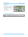
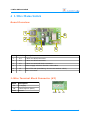
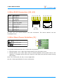
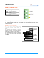
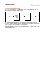
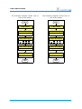
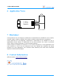
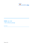
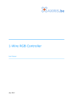
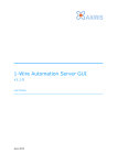
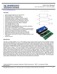
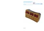
1-Wire Mains Switch
User Manual
July 2013
1-Wire Mains Switch
Table of Contents
1
Features
3
2
Technical Specifications
3
3
Safety Precautions
4
4
1-Wire Mains Switch
Board Overview
1-Wire Terminal Block Connector (K2)
1-Wire RJ45 Connectors (K3, K4)
1-Wire Slave Power Selection (J1)
Mains Connector (K1)
1-Wire Connectivity
Communications Protocol
5
5
5
6
6
7
7
8
5
Software Support
ows
owfs
10
10
10
6
Application Notes
11
7
Disclaimer
11
8
Contact Information
11
Revision History
Date
Authors
Description
2013-03-14 Peter S'heeren
Initial release.
2013-04-28 Peter S'heeren
Added extra safety precaution.
Added section about software support.
Second release.
2013-07-21 Peter S'heeren
Added section about owfs software support.
Third release.
2
User Manual
1-Wire Mains Switch
1 Features
▪
Available in 230 V and 120 V versions.
▪
Reinforced safety insulation between
mains voltage and one wire bus.
▪
Low power consumption, typically less
than 400 mW.
▪
Three connection points
cabling and wiring.
for
1-Wire
2 Technical Specifications
Weight
47 g (with fuse)
Dimensions
96 mm x 54 mm x 18 mm (W x D x H)
User Manual
3
1-Wire Mains Switch
3 Safety Precautions
SAFETY PRECAUTIONS
DO NOT TOUCH THE DEVICE WHEN IT IS CONNECTED TO MAINS VOLTAGE.
DO NOT MOUNT OR PLACE THE DEVICE CLOSE TO INFLAMMABLE MATERIALS.
USE A FUSE OF 50 mA ONLY.
THE LOAD CIRCUIT MUST BE PROTECTED BY AN EXTERNAL FUSE OF MAX. 10 A.
DO NOT USE THE DEVICE WITH APPLIANCES THAT MAY CAUSE DANGER WHEN
SWITCHED ON OR OFF UNINTENDEDLY.
AFTER BEING DISCONNECTED FROM THE MAINS VOLTAGE, CAPACITOR C6 MAY REMAN
CHARGED. THE DEVICE MAY GENERATE A HARMLESS BUT UNPLEASANT ELECTRIC
SHOCK WHEN YOU TOUCH THE MAINS CONNECTOR K6.
It's recommended to house the device in an earthed metal case.
4
User Manual
1-Wire Mains Switch
4 1-Wire Mains Switch
Board Overview
1
6
2
3 4
5
Mark
Label
Description
1
K3
1-Wire bus RJ45 connector
2
K4
1-Wire bus RJ45 connector
3
K2
1-Wire bus terminal block connector
4
J1
Power supply selection for the 1-Wire slave
5
F1
Fuse of 50 mA (mandatory; do not use another value)
6
K1
Mains connector
1-Wire Terminal Block Connector (K2)
Mark
Description
5V
5 V supply
1W
1-Wire DQ line (data)
GND
Ground
GND 1W
User Manual
5V
5
1-Wire Mains Switch
1-Wire RJ45 Connectors (K3, K4)
Mark
Description
1
Unassigned
2
+5 V power
3
Unassigned
4
1-Wire DQ (data)
5
1-Wire ground
6
Unassigned
7
Unassigned
8
Unassigned
1 2 3 4 5 6 7 8
1 2 3 4 5 6 7 8
Plug
top view
Receptacle
front view
All eight pins are routed between the two connectors. The device doesn't use the
unassigned lines.
1-Wire Slave Power Selection (J1)
1 2 3 Description
External power
Parasite power
3
2
1
This jumper determines how the 1-Wire slave is powered:
▪
External power: the 1-Wire slave draws power from the mains circuit.
▪
Parasite power: the 1-Wire slave uses an internal capacitor as its power source. The
capacitor is charged during idle time (DQ line held high) and provides power during
bus activity.
Note: The 5V line (K2, K3, K4) is never applicable.
See the 1-Wire specification for more information.
6
User Manual
1-Wire Mains Switch
Mains Connector (K1)
Mark
Description
LOAD
Load being switched
LOAD
N/LOAD Neutral
Load being switched
L
N/LOAD
Phase
L
Connect the 230 V or 120 V mains between N/LOAD and L.
The load being switched must be connected between LOAD and N/LOAD.
For reasons of safety, make sure you connect the phase conductor and the neutral
conductor correctly.
1-Wire Connectivity
The 1-Wire Mains Switch provides three
connection points for 1-Wire cabling and
wiring.
5V 1W GND
The terminal block connector is typically
used for wiring the 1-Wire Mains Switch to
an AbioWire or another 1-Wire adapter.
The RJ45 receptacles provide a means to
set up a 1-Wire bus in daisy chain using
UTP cables.
K3
RJ45
receptacle
K4
RJ45
receptacle
1
User Manual
Terminal
block
connector
K2
2
3
4
5
6
7
8
7
1-Wire Mains Switch
Communications Protocol
The 1-Wire slave function on the 1-Wire Mains Switch is a Maxim DS2406 chip. The 1Wire slave is connected to the switch controller.
1-Wire
DQ
DS2406
1-Wire
slave
PIO-A
Switch
controller
SWITCH
See the Maxim DS2406 datasheet for more information about the 1-Wire slave chip.
The switch controller interprets the PIO-A input as negative logic. Doing so insures the
switch is turned off when the DS2406 is in the reset state.
The family code of the DS2406 is 12h. Since the family code alone doesn't uniquely
identify a 1-Wire Mains Switch device, the host system must associate the full 8-byte
ROM code with the device.
8
User Manual
1-Wire Mains Switch
The following diagram shows how to
turn on the switch.
The following diagram shows how to
turn off the switch.
start
start
1-Wire Reset
1-Wire Reset
1-Wire Write Byte
1-Wire Write Byte
55h (match ROM)
55h (match ROM)
1-Wire Write Bytes
1-Wire Write Bytes
12h xxh xxh xxh
xxh xxh xxh xxh
12h xxh xxh xxh
xxh xxh xxh xxh
1-Wire Write Bytes
1-Wire Write Bytes
F5h 04h FFh
F5h 04h FFh
1-Wire Write Bit
1-Wire Write Bit
0
1
stop
stop
User Manual
9
1-Wire Mains Switch
5 Software Support
ows
Software package ows v1.0.0 and later includes program owswitch. This program
enables you to fully control the 1-Wire Mains Switch.
Example invocations of the program:
# ./owswitch -i2cdev /dev/i2c-0 ds2482 24 -ch 7 -id 12-974696 -on
This command turns on the switch. The device is supposed to be connected to channel 7
of the DS2482-800 chip.
> owswitch.exe -lu -pr -id 12-974696 -off
This command probes the 1-Wire Mains Switch on all USB-to-1-Wire adapters. If found,
the program turns off the switch.
owfs
It's assumed you're using the filesystem client of the owfs package. In the examples it's
suppose you've specified /mnt/onewire/ as the mount directory for the 1-Wire file
system.
Since owfs inverts all accesses to PIO channels, the default negative logic becomes
positive logic.
# echo "1" > /mnt/onewire/12.964697000000/PIO.A
This command turns on the switch.
# echo "0" > /mnt/onewire/12.964697000000/PIO.A
This command turns off the switch.
10
User Manual
1-Wire Mains Switch
6 Application Notes
1-Wire
Switch
LOAD
N/LOAD
L
120V or 230V
7 Disclaimer
Axiris products are not designed, authorized or warranted to be suitable for use in space,
nautical, space, military, medical, life-critical or safety-critical devices or equipment.
Axiris products are not designed, authorized or warranted to be suitable for use in
applications where failure or malfunction of an Axiris product can result in personal
injury, death, property damage or environmental damage.
Axiris accepts no liability for inclusion or use of Axiris products in such applications and
such inclusion or use is at the customer's own risk. Should the customer use Axiris
products for such application, the customer shall indemnify and hold Axiris harmless
against all claims and damages.
8 Contact Information
Official website: http://www.axiris.be/
User Manual
11