1
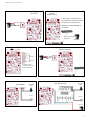
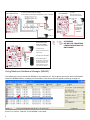
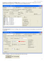
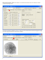
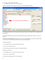
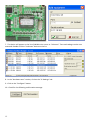
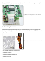
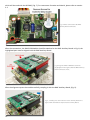
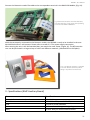
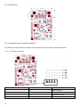
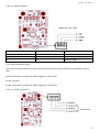
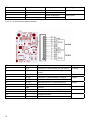
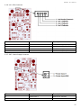
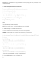
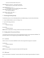
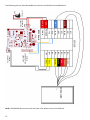
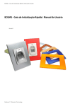
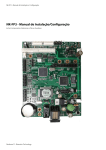
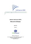
BCGMG Quick Start Guide / User Manual
BCGMG Quick Start Guide / User Manual
Version 1.1
Neokoros IT - Biometric Technology
ATTENTION! STATIC ELECTRICITY SENSITIVE DEVICE!
The BCGMG, just like any other electronic device, is susceptible to irreparable
damage caused by occasional static electricity discharge in its inner board
and components. It is essential to carry out the static electricity unloading
from the body prior any installation/operation procedures. It is strongly recommended to avoid any unnecessary contact with the device components.
WARNING: damages caused by static electrical discharges are NOT covered
by the End User Warranty Certificate!
To discharge static electricity, consider the following procedures before any
operation including the BCGMG:
1 - With your computer off, make sure it is grounded keeping its power cord plugged into a 3 prong grounded outlet.
2 - Touch - for few seconds - a bare metal frame (not a painted or coated surface) of the computer case.
Turn the computer on.
3 - With the computer on, repeat the step 2. Keep your hand in contact with the computer case for few
seconds.
4 - Consider to use a static eletricity discharging wristband to perform long operations using the BCGMG.
Electricity discharging wristbands are available in electronics supplies stores. Please refer to manufactures
instructions to static electricity discharging optimization.
5 - The device now is ready for assembling and connections. Avoid unnecessary contact with the device components.
ATTENTION!
AVOID INAPPROPRIATE DISPOSAL OF THIS DEVICE AND ITS COMPONENTS!
This device is made using electronic components which can be harmful to environment if not properly disposed. Please check your local rules and regulations for the proper disposal and recycling of this device and its components
after the end of its life cycle.
ATTENTION!
DO NOT USE CAPACITORS FOR RECIRCULATION! USE ONLY DIODE!
This document is divided in two main sections: “BCGMG Quick Start Guide”
and “BCGMG User Manual”. The first section content is based in simplified
diagrams of the BMC Auxiliary Board of the BCGMG Device. Despite the information present in the first section, we strongly recommend the reading of the
“User Manual” section for a detailed explanation of the connectors, configuration parameters and other settings.
Neokoros IT. All Rights Reserved © 2010 - 2014.
BCGMG - Quick Start Guide
BCGMG - Quick Start Guide
Power Supply
10~24 VDC
Power Supply
Injector
(Network cable)
In this mode, the power supply is
transmitted thru the network cable
using the blue and brown pairs.
10~24 VDC
GND
WARNING: Not PoE (IEEE802.af)
compatible.
Injector
Communication (Serial Port)*
J8
Communication
(Ethernet Network)
J7** Jumpers
B } RS-485
A
RX RS-232
TX }
GND
RX } TTL
TX
RX } TTL
TX
GND
RX RS-232
TX }
}
}
Serial 2
10~24 VDC
10~24 VDC
GND
Serial 1
**NOTICE: Jumpers
J7 or J8 must be closed
for RS-232 utilization
*External devices control only
Sensors
Sensors
Pushbutton
(NO)
IN1+
IN1IN2+
IN2IN3+
IN3IN4+
IN4-
Pushbutton
(NO)
Sensor
NO1
NC1
COM1
NO2
NC2
COM2
RXD
TXD
GND
PWD-IN
(thru BCGMG)
(thru GIO terminal)
Sensor
10~24 VDC
Control Outputs
Control Outputs
(thru BCGMG)
IN1+
IN1IN2+
IN2IN3+
IN3IN4+
IN4-
(thru GIO terminal)
WARNING: DIODE INSTALLATION IS REQUIRED FOR LOCKS
OF ANY TYPE. DIODE TYPE REF: 1N4007.
WHITE STRIPE OF THE DIODE IS CONNECTED TO THE + TERMINAL
Strike Locks: Use relay’s NO
and COM.
Electromagnetic Locks:
Use relay’s NC and COM.
Electromagnetic
Lock
NO1
NC1
COM1
NO2
NC2
COM2
RXD
TXD
GND
PWD-IN
Diode
WHITE STRIPE
OF THE DIODE
IS CONNECTED
POSITIVE (+)
TERMINAL
Diode
Electromagnetic
Lock
NC
10~24 VDC
Card Reader
Card reader types
Codes for settings
1 - Mifare SRT Neokoros
2 - RFID 125 Khz
(any protocol like Acura’s)
NO
C
ATTENTION!
DO NOT USE CAPACITORS
FOR RECIRCULATION! USE
ONLY DIODE!
3 - Bar Code
PWD
GND
RX
TX
8 - Mifare Duali DE-ABM6
9 - Acu Mifare AM-11
NOTE: Some card readers
use only the RX pin of J5
connector. See Card S1
and S2 references in the
“User Manual” Section
Using Neokoros Hardware Manager (NKHM)
The NKHM main screen shows the BCGMG in the products list. The program also shows other information
about the BCGMG device, including the IP Number. If the device dos not appear, please go to page 11. Press F5 or click on “Refresh” if the BCGMG is not listed.
BCGMG - Quick Start Guide
Hardware and Device Configuration: For hardware tests and device configuration, select BCGMG in the list and press “Ctrl” + “T”. This will invoke the following screen:
IP Configuration: Click on “IP Settings” Tab. On the screen, the panel “New Settings” will show the following data:
Click on “Configure”. Check for the following confirmation message:
Devices & Sensors Test: Click “Devices” to run devices and sensors tests. The “Devices” tab will
invoke the following screen:
To perform a biometric reading test, click on “Image” tab. This section allows to check the fingerprint image
or a video image if the device is connected to a camera:
BCGMG - Quick Start Guide
Card Reader Test: click “Notifications” tab to a list of card readers. Select the “Auto show” function.
Selecting Status: In the “Settings” tab > “Numerical” button, it is possible to choose the device operation mode. Options are “Off-line” (for StandAlone operation), “On-line” and “Fallback (stays on-line while
server is active”). Function is not saved when the unit is turned off. Please refer to “8.1 - Mode” parameter
in the User Manual section.
Editing Configuration Parameters Values: Configuration parameters values can be easily edited using Neokoros Hardware Manager. Please follow the steps below:
1 - With the BCGMG connected, run the NKHM application.
2 - Double click on the device name on the list.
3 - Click on the “Settings” tab.
4 - In “Show” click on “Editor (CA)” button.
5 - In “Configuration file (CA)”, click on “Read” button.
The device parameters will be listed on the screen as the following picture shows:
6 - Edit parameters/values in the parameters list and then click the “Save” button of the “Configuration file
(CA)” section.
For detailed information about the main parameters and its values, please refer to sections 4 to 8 in this
manual.
Firmware Load/Update: NKHM application allows to load/update the firmware of the selected device in its main screen. To load a firmware file, proceed as described below:
To load a firmware file:
1 - In the NKHM main screen, select the device on the list.
2 - Click on the “Firmware” button.
3 - Select a firmware file and click “Open” in the dialogue window.
To update a firmware file:
1 - In the NKHM main screen, select the device on the list.
2 - Click on the “Update” button.
3 - Confirm the update operation in the message box.
10
BCGMG - Quick Start Guide
WARNING: It is strongly recommended the backup of the original files prior any other operation envolving
parameters changes and/or any firmware file substitution. Firmware files must be provided by NEOKOROS
Authorized Customer Support Service.
If the Device does not Appears in the List...
... and you are sure the network is ok, the main reason is due the differences between the network and
device configuration. Please follow the steps below:
1 - Connect the device to the computer using a crossover network cable.
2 - Using the NKHM application, click on “More” > “Add equipment”.
3 - Type a PC compatible IP value.
4 - Type the equipment serial number. This can be retrived from the internal tag attached to the GMG-120
processor module.
5 - Enter the serial number using the format A:BB:CC:DDD. For example, for serial number
0-11-19-302 use the format 0:11:19:302.
6 - Click on “Ok”
11
7 - The device will appear on the list of NKHM main screen as “Unknown”. Tests and settings can be now
executed. Double click the “Unknown” device on the list.
8 - In the “Hardware tests” section, click on the “IP Settings” tab.
9 - Click on the “Configure” button.
10 - Check for the following confirmation message:
12
Annotations
13
BCGMG - User Manual
14
BCGMG User Manual - Contents
1 - Introduction/Main Features. ......................................................................................................... 17
2 - Assembling/Connectors.................................................................................................................. 18
3 - Specifications (BMC Auxiliary Board). ......................................................................................... 21
3.1 - Dimensions.................................................................................................................................... 22
3.2 - Connectors (pin out and functions)............................................................................................... 22
3.2.2: J3 - Relay Connector............................................................................................................ 23
3.2.3: External Device Control....................................................................................................... 23
3.2.4: J4 - Sensors Connector........................................................................................................ 23
3.2.5: J5 - Serial Communication Connector................................................................................. 24
3.2.6: J10 - LEDs Connector........................................................................................................... 25
3.2.7: CN7 - Power Supply Connector............................................................................................ 25
4 - BMC Board/Module GIO Connection............................................................................. 26
5 - BMC Board/Card Reader Connection............................................................................. 26
6 - BMC Board/CLP Dexter μDX200/201 RS 485 Conn. (Home Automation)...................... 27
7 - Disabling/Enabling Beeps............................................................................................... 28
8 - Configuration Parameters/Values.................................................................................. 28
8.1 - AutoGrab........................................................................................................................................28
8.2 - HBInterval.......................................................................................................................................28
8.3 - HBThreshold...................................................................................................................................29
8.4 - IgnoreSchedule...............................................................................................................................29
8.5 - MasterPwd.....................................................................................................................................29
8.6 - MIWA..............................................................................................................................................29
8.7 - Mode..............................................................................................................................................31
8.8 - Module...........................................................................................................................................31
8.9 - MonitorUp / MonitorDown............................................................................................................31
8.10 - PortCmd.......................................................................................................................................32
8.11 - PortImg.........................................................................................................................................32
8.12 - PushButton...................................................................................................................................32
8.13 - RedLedTime..................................................................................................................................32
8.14 - Relay.............................................................................................................................................32
8.15 - RelayNr.........................................................................................................................................33
8.16 - RelayTime.....................................................................................................................................33
8.17 - RelayTimeNr.................................................................................................................................33
8.18 - SendEvents (ReSubmitRecMa).....................................................................................................33
8.19 - SendImage....................................................................................................................................34
8.20 - SendTemplate...............................................................................................................................34
15
16
BCGMG - User Manual
1 - Introduction/Main Features
The BCGMG is a versatile device for access control used in both residential and corporative environments.
Its features include easy installation and utilization. Besides its small size, the device incorporates the latest
reading and identification technology. According to the highest required quality standards, the BCGMG also
features total support for communication ports.
Some other BCGMG features:
- BTicino high impact/resistance enclosure;
- Standard 4X2 box for wall fixation;
- Capacity up to 12,000 (twelve thousand) fingerprint digital registers in “StandAlone mode”. Unlimited in
“on line mode” (according to the parameter settings and the license type for people flow control);
- Serial RS-232 (02 ports), RS-485 (01 port) for automation and auxiliary devices control;
- Uses 5546 and 5548 UDP Ethernet ports for communication (commands and images, respectively);
- Electroluminescent biometric reader;
- 10 to 24 v. power supply; (use 12VDC 500mA for BCGMG. Increase amp. if used to control door locks);
- External trigger relay;
- Identification of digital features in about 1 second; (average of 0,8 seconds in “on line” mode).
The device enclosure case contains two main boards:
- GMG 120: Processing and control module;
- BMC: Auxiliary Board consisting of connectors coupled to GMG 120 Module. Allows network connection,
RS-232 and RS-485 serial communication, control of relay based external device, provides LEDs for visual
indication and a buzzer for audible general signaling.
Fig.1: The BMC Auxiliary Board. Fig 2: The GMG 120 Module, for device processing and overall control.
Fig.1: BMC Auxiliary Board.
Several connectors to external communication.
Fig.2: GMG 120 Module: Device
overall processing and control
unit.
17
The general BCGMG components arrangement when assembled, are similar to the image shown in Fig. 3:
GMG 120 Module coupled to the BMC Auxiliary Board.
Fig.3: BCGMG Device: Assembled by the GMG 120 Module
(top) and the BMC Auxiliary Board.
2 - Assembling/Connectors
Please make sure to check if all required cables and screws for assembling are present; (Fig.4). The BMC
Auxiliary Board shall be firmly secured in the BTcino enclosure. Board connectors must be identified according the image shown in Fig. 5:
Fig.4: Screws, connectores and cables used in the assembly
of the device.
- CN7: 10 to 24V power supply input connector;
- J1: Ethernet connector;
- J3: Relay connector (NO, COM and NC);
- J4: Sensors connector;
18
BCGMG - User Manual
Fig.5: BMC Auxiliary Board connectors.
- J5: Serial communication connector;
- J10: LEDs connector.
Please make sure the flat cable is connected to the biometric reader before the BMC Auxiliary Card fixation
in the BTCino enclosure. Fig.6 shows the biometric card reader side view. The biometric reader is connected
to the flat cable and properly positioned into the BCGMG device enclosure.
After securing the Auxiliary Board with the screws, please make the appropriate connections to the devices
Fig.6: Flat cable connected to the biometric reader
already properly positioned in the device enclosure.
19
which will be used with the BCGMG; (Fig. 7). For connectors functions and details, please refer to section
3.2.
Fig.7: Cables connected to the BMC
Auxiliary Board connectors.
After the connections, the GMG 120 Module should be attached to the BMC Auxiliary Board. In Fig. 8, the
highlighted part must be aligned with the BMC Auxiliary Board.
Fig.8: Align the GMG 120 Module terminals
(highlighted in the figure) with the BMC Auxiliary
Board connectors. Then...
After the alignment press the module carefully, coupling it with the BMC Auxiliary Board; (Fig. 9).
Fig.9: ...carefully press the module over the Auxiliary Board. The
figure shows the Module coupled to the Auxiliary Board.
20
BCGMG - User Manual
Connect the biometric reader flat cable to the correspondent terminal in the GMG 120 Module; (Fig. 10).
Fig.10: Connect the other end of the flat cable,
from the biometric reader, to the corresponding
terminal in the GMG 120 Module.
With the set properly connected to the biometric reader, the BCGMG is ready to be installed in the standard 4X2 box where it will operate. Please refer to section 3.2.7 for power supply connection.
After securing the unit in the 4X2 standard box, just attach the outer frame; (Figure 11). The BTcino enclosure can be purchased in a large variety of colors and different materials; (standard BTcino 4X2 plate).
Fig.11: The BTcino enclosure is available
in several different colors for perfect
fitting in any kind of environment.
3 - Specifications (BMC Auxiliary Board)
Item
Specification
Network Communication Speed
Serial Ports
Leds
Buzzer
Relay
10/100 Mbits
02 RS-232 or TTL ports. 01 RS-485 port
03 Leds for visual indication
01 Buzzer for audible general signaling
01 SPDT Relay for external device control
21
3.1 - Dimensions
3.2 - Connectors (pin out and functions)
The following sections describe the BMC Auxiliary Board pin out and their respective functions.
3.2.1: J1 - Ethernet Connector
Pin
Function
Description
1
2
3
4
RX RX +
TX TX +
Data reception Data reception +
Data transmission Data transmission +
22
BCGMG - User Manual
3.2.2: J3 - Relay Connector
Tolerance: 1A / 30V
Pin
Function
Description
1
2
3
NC
COM
NO
Normally-Closed
Common
Normally-Open
3.2.3: External Device Control
To control an external device, connect the wires from the J3 connector directly from the board internal
relay.
Pin 01: Connection is always ON. When triggered, it will be OFF.
Pin 02: Common.
Pin 03: Connection is always OFF. When triggered, it will be ON.
3.2.4: J4 - Sensors Connector
} Pulse Sensor
23
Pin
Function
Description
Sensor Type
1
2
3
4
IN
GND
IN
GND
Sensor 1 IN (Input)
Sensor 1 GND (Ground)
Sensor 2 IN (Input)
Sensor 2 GND (Ground)
Dry Contact
Pulse Sensor
3.2.5: J5 - Serial Communication Connector
Pin
Function
Description
Jumpers
1
2
Tx1D
Rx1D
J7 closed
3
4
5
6
7
8
9
10
11
12
GND
Tx1TTL
Rx1TTL
Tx2TTL
Rx2TTL
GND
Tx2D
Rx2D
A
B
Serial Port 1 Transmit data (RS-232 Levels)
Serial Port 1 Receive data from (RS-232
Levels)
Ground
Serial Port 1 Transmit data (TTL Levels)
Serial Port 1 Receive data (TTL Levels)
Transmits data to TTL Level Serial Port
Transmits data from TTL Level Serial Port
Ground
Transmits data to Serial RS 232 Port
Receives data from Serial RS 232 Port
RS-485 Serial Port
RS-485 Serial Port
24
J7 open
J8 open
J8 closed
BCGMG - User Manual
3.2.6: J10 - LEDs Connector
Pin
Function
Description
1
2
K
A
Led 5V Anode (Common)
Led 1 Cathode (Red)
3
4
A
A
Led 2 Cathode (Green)
Led 3 Cathode (Blue)
Pin
Function
Description
1
2
Power Input +
Power Input GND
Positive (10~24 VDC)
Power Ground
3.2.7: CN7 - Power Supply Connector
25
Suggestion: Use 12V 500mA power supply for BCGMG. Increase amperage if the same power suplly is used
to control door locks.
4 - BMC Board/Module GIO Connection
To connect the BMC board to a GIO Module, execute the steps below:
1 - Close the J8 Jumper with solder;
2 - Connect to serial port 2 RS-232:
- RX wire of the GIO Module to the pin 9 (TX) of the BMC Board;
- TX wire of the GIO Module to the pin 10 (RX) of the BMC Board;
3 - Using the NKHM software, open the “Settings” tab;
4 - Type the following parameter:
GIO=1
This configuration will activate the module.
NOTE: To use the GIO Module, the CardS2 configuration must be disabled.
5 - BMC Board/Card Reader Connection
To connect the BMC board to a card reader, please execute the steps below:
WARNING: TTL and RS-232 level can not be used simultaneously in the same port.
1 - Close the jumper J7 for serial 1 or J8 for serial 2 to enable RS-232 pins. Leave it open for TTL Level.
2 - Connect:
Serial 1 RS-232 Level
- RX wire from the first reader to the pin 1 of the BMC Board;
- TX wire from the first reader to the pin 2 of the BMC Board;
Serial 2 RS-232 Level
- RX wire from the second reader to the pin 9 of the BMC Board;
- TX wire from the second reader to the pin 10 of the BMC Board;
Serial 1 TTL Level
- RX wire from the first reader to the pin 4 of the BMC Board;
- TX wire from the first reader to the pin 5 of the BMC Board;
Serial 2 TTL Level
- RX wire from the second reader to the pin 6 of the BMC Board;
- TX wire from the second reader to the pin 7 of the BMC Board.
3 - Using the NKHM software, open the “Settings” tab;
26
BCGMG - User Manual
4 - Type the following parameters:
CardS1=X
CardS2=X
-> (where “X” is the value which should match the connected card reader code)
0-None
1-Mifare SRT Neokoros
2-RFID 125 Khz (any with protocol like Acura’s)
3-Bar Code + Code Reader
8-Mifare Duali DE-ABM6 ASCII
9-Acu Mifare AM-11
NOTE: To use a second card reader, the GIO configuration must be disabled.
6 - BMC Board/CLP Dexter μDX200/201 RS 485 Connection (Home Automation)
To connect a BMC board with a μDX200/201, follow the steps below:
1 - Connect the CLP A pin to the pin 11 in the BMC Board;
2 - Connect the CLP B pin to the pin 12 in the BMC Board;
3 - Connect the CLP GND wire to the GND wire in the BMC Board;
4 - Using the NKHM software, open the “Settings” tab;
5 - Type the following parameters:
uDX.Clp0Enabled=(0=disabled, 1=enabled)
-> enables or disables the communication with CLP
uDX.Clp0Addr=(0, 1, 2, 3, ...)
-> correspondent value to the DNXET address in the CLP
uDX.Clp0ComType=(0=tcp/ip, 1=rs-232, 2=rs-485)
-> communication type (network, serial 232 or serial 485)
uDX.Clp0TcpMode=(0=client, 1=server)
-> tcp/ip mode (client or server)
uDX.Clp0Var=(1, 2, 3, ...)
-> number of variable to be accessed in CLP
uDX.Clp0BaudRate=(110, 300, 1200, 2400, 4800, 9600, 19200, 38400, 57600, 115200, 230400, 460800,
921600)
-> communication speed with the CLP
uDX.Clp0DataBits=(5, 6, 7, 8)
-> data bit communication with the CLP
uDX.Clp0StopBits=(0, 1)
-> stop bits to communication with the CLP
uDX.Clp0Parity=(0=par, 1=impar, 2=nenhum)
27
-> parity for communication with the CLP
uDX.Clp0FlowCtrl= (0=rts/cts , 1=xon/xoff, 2=nenhum)
-> flow control for communication with the CLP
uDX.Clp0MyAddr=(0, 1, 2, 3, ...)
-> corresponding value to the DXNET data collector address
uDX.Clp0Ip=(192.168.0.1, xxx.xxx.xxx.xxx, ...)
-> CLP network ip address
uDX.Clp0Port=(1000, 1001, 5000, ....)
-> CLP network port
7 - Disabling/Enabling Beeps
The BMC Board buzzer can be disabled/enabled by the NKHM settings. Proceed as described below:
1 - Using the NKHM software, open the “Settings” tab;
2 - Type the following parameters:
BuzzerOff=1
-> (disables beeping).
BuzzerOff=0
-> (enables beeping).
NOTE: When the parameter is missing, the device will remain with the buzzer on.
8 - Configuration Parameters/Values
The following sections describe other several configurable parameters used to operate the BCGMG. The
parameters values can be changed using the NKHM software “Settings” tab.
8.1 - AutoGrab
When a camera is connected to BCGMG it sends a video image when a fingerprint is captured:
AutoGrab=0
-> (default, disabled).
AutoGrab=1
-> (enabled).
NOTE: Camera hardware must generate compressed JPG image data.
8.2 - HBInterval
Sets the time between “heartbeats” responses after which the equipment goes StandAlone if mode=2;
28
BCGMG - User Manual
(Please refer to topic 8.7). Use the syntax:
HBInterval=X
-> (where “X” must a value for time in hundredths of seconds. Default = 100).
Value also can be set using hexadecimal notation. Example for 100 (default value): HBinterval=0x0064.
8.3 - HBThreshold
Sets the time limit for “heartbeats” responses, after which the equipment goes off-line. Use the syntax:
HBThreshold=X
-> (where “X” must a value for time in hundredths of seconds. Default = 500).
Value also can be set using hexadecimal notation. Example for 500 (default value): HBThreshold=0x01f4
8.4 - IgnoreSchedule
BCGMG has no real-time clock. When BCGMG is activated the internal clock will show a incorrect date. For
this reason there is the parameter to ignore the timetable. The access is granted in full time (24h) to who is
allowed in the data collector device.
IgnoreSchedule=0
-> (Ignore schedule is off - default).
IgnoreSchedule=1
-> (Ignore schedule is on).
8.5 - MasterPwd
Sets a master password to access the menu using the keyboard.
MasterPwd=XXXXXXXXXXXXXXX
-> (where “X” is a value of 1 up to 15 characters).
8.6 - MIWA
This parameter is used to enable or disable a MIWA Lock. Requires GIO110 module for utilization.
The setting will only take effect if the option GIO=1.
Please refer to section 4 - “BMC Board/Module GIO Connection”.
Miwa=0 (default)
-> disables Miwa mode.
Miwa=1
-> enable Miwa mode.
29
The following picture, describes MIWA connections to GIO110 and the BMC Board:
+
COM2
NO2
NC2
COM1
NO1
IN3-
IN3+
IN2-
IN2+
IN1-
IN1+
Relay
YELLOW
BLACK
RED
ORANGE
WHITE
GIO 110
RXD
IN4+
Relay
NC1
TXD
IN4-
BROWN
PWR-GND
BLUE
GND
PWR-IN
BMC Board
10RX
9TX
J5 SERIAL
COMMUNICATION
CONNECTOR
10~24 VDC
+
GND
CN7 POWER
CONNECTOR
J3 RELAY
CONNECTOR
MIWA LOCK
30
10~24VDC
GND
NC COM NO
NOTE: GIO/BCGMG Ground must be the same if the power sources are different.
BCGMG - User Manual
8.7 - Mode
Sets the equipment operation mode.
Mode=0:
-> StandAlone only: The equipment will operate in standalone mode, using an internal database
stored in its memory.
Mode=1:
-> On line only. The device will work connected directly to a computer and send fingerprint images/
templates or keyboard/card events to that computer.
Mode=2:
-> Fallback (default): The device will work connected to a computer, but if the computer stops responding, it will work in standalone mode.
8.8 - Module
The “module” parameter allows to enable or disable the biometric device reading. Use it to activate or
deactivate the fingerprint reader.
Module=1
-> (enables biometric reading - default).
Module=0
-> (disables biometric reading).
8.9 - MonitorUp / MonitorDown
These parameters are used to monitor the sensor state. Any change of the state is registered and sent to
the server. For on line use only.
MonitorUp=X
-> where “X” is a value correspondent to a sensor
MonitorDown=X
-> where “X” is a value correspondent to a sensor
X is an integer value that is interpreted in a range of 8 bits. Each bit of the value on or off corresponds to
monitoring the corresponding sensor.
Sensors 0 and 1 are internal BCGMG sensors. Sensors 2, 3, 4 and 5 are GIO ones.
In binary, each sensor means one bit and the zero sensor is the less significant.
Example:
To monitor sensors 5 and 0, the “X” value is 33 that is equivalent to the 100001 binary value.
31
8.10 - PortCmd
Change the default command port. Default: 5546 UDP. This parameter is very useful when several equipments are installed in a web based application and they must be routed thru the network.
PortCmd=X
-> where “X” is a value correspondent to a port
8.11 - PortImg
UDP port for digital fingerprint images transmission. Default port is 5548
PortImg=X
-> where “X” is a value correspondent to a port
8.12 - PushButton
When a value is applied, the correspondent sensor is monitored and treats it like a pushbutton to activate
the relay (for example, to opening doors and gates). Syntax for the parameter is:
Pushbutton=X
->(where “X” must a value for the desired sensor):
-1 (default - no monitoring)
0-internal sensor
1-internal sensor
2-GIO input (GIO connection required)
3-GIO input (GIO connection required)
4-GIO input (GIO connection required)
5-GIO input (GIO connection required)
NOTE: For the option PushButton work, the equipment must be operating in StandAlone mode.
8.13 - RedLedTime
Sets the duration time for the red led stay lit; (default = 500 centiseconds)
RedledTime=150
-> a second and a half
8.14 - Relay
Specifies which relay will be activated when operating in StandAlone mode. Use the syntax:
Relay=X
-> (where “X” is the value which corresponds to the desired relay)
32
Annotations
0-No Relay is activated
5-Internal BCGMG Relay is activated
6-GIO Relay1 is activated - GIO connection required
7-GIO Relay2 is activated - GIO connection required
8.15 - RelayNr
Specifies which relay must be activated when there is no recognition:
RelayNr=X
-> (where “X” is the value which corresponds to the desired relay)
0-No activation
5-Internal BCGMG Relay is activated
6-GIO Relay1 is activated - GIO connection required
7-GIO Relay 2 is activated - GIO connection required
8.16 - RelayTime
Sets the relay activation time in case of recognition using the syntax:
RelayTime = value
-> (where “value” must be a number between 0 to 12000 hundredths of seconds. Default: 500 = 5
seconds).
External relay activation requires GIO connection.
WARNING: Very high values used for the relay operation can be harmful for some kinds of devices, mainly
electric door locks.
8.17 - RelayTimeNr
Sets the relay activation time in case of no recognition using the syntax:
RelayTimeNr = value
-> (where “value” must be a number between 0 to 12000 hundredths of seconds. Default: 500 = 5
seconds).
8.18 - SendEvents (ReSubmitRecMa)
StandAlone operation mode records are automatically sent to server when the connectioin is restablished.
SendEvents=0
-> records are not sent (default)
SendEvents = 1
-> send records
Example of recorded events sent when the parameter is set to 1 value:
33
TE_FreeAcess = 7 (reserved)
TE_TurnTimeout = 8 (reserved)
TE_WaitTurn = 9 (event recorded when the person is identified and waiting turnstile’s spin
TE_DoorAlarm = 10 (recorded when a door alarm is activated)
8.19 - SendImage
Enables sending a fingerprint image for each fingerprint captured in online mode:
SendImage = 0
-> disables sending images
Sendimage = 1 (default)
-> enables sending images
8.20 - SendTemplate
Enables sending a fingerprint template for each fingerprint captured in online mode:
SendTemplate=0
-> disables sending templates
SendTemplate=1
-> enables sending templates (default)
34
Warranty Certificate
End User Limited Warranty Certificate
NEOKOROS IT uses the latest technology in the production of all the components used for the assembly and
operation of their equipment, ensuring its products against manufacturing defects. This warranty covers
defects in workmanship for a one (1) year period to the end customer since the installation of the related
product and any related component is performed by authorized NEOKOROS IT personnel. This Warranty
Certificate will be valid when presented with the invoice and the product/equipment serial number. In case
of any defect – properly diagnosed and confirmed by the NEOKOROS Authorized Customer Support Service
– replacement of any parts, components and/or accessories required for the perfect equipment function
performance will be provided without any cost to the end customer.
WARRANTY CANCELLATION
This Warranty Certificate will be canceled if the defect is consequent of the following situations:
- Operation in violation of the specified conditions described in the product instruction manuals or in violation of any specified condition explained by the NEOKOROS technical staff;
- Misuse, accident, fall or use of the product in conjunction with any other equipment not previously approved, recognized and/or authorized by NEOKOROS IT;
- Inadequate transport and storage of the product and its components, including its assembling units and
accessories, unauthorized modification, execution of procedures which denote any reverse engineering attempt, maintenance services performed by unauthorized personnel;
- Lightning, power surges, fluctuations in the power grid, damages caused by bad weather conditions,
flooding or any other natural phenomena;
- Violation/removal of the product/equipment Warranty Seal.
HANDLING AND SHIPPING
Expenses due displacement of technicians, transportation of parts, components, handling and insurance
covering are the responsibility of the end customer.
Product/Model Description:
Product Serial Number:
35
Neokoros IT Ltd. – Biometric Technology.
All Rights Reserved: © 2010 – 2014.
No part of this document may be reproduced without the prior permission of Neokoros IT.
Specifications subject to change without notice.
36