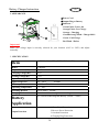
1
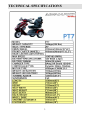
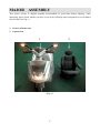
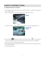
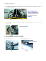
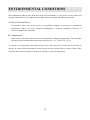
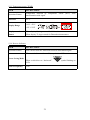
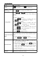
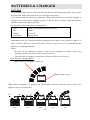
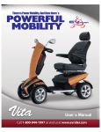
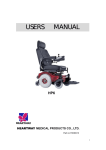
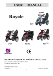
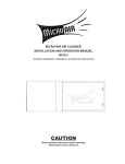
CONTENTS 1. Technical Specification…………….................................…………….3 2. M a j o r A s s e m b l y … … … … … … … … … … … … … … … … … … … … … . . 4 3. Safety Instruction……………………………………………………....5~8 4. E n v i r o n m e n t C o n d i t i o n … … … … … … … … … … … … … … … … … … . . 9 5. Wa r r a n t y … … … … … … … … … … … … … … … … … … … … … … … … . . 1 0 6. Assembly Instruction…………………………………………………..11~12 7. Adjustment For Seating Comfort……………………………….……..13~15 8. Specification Of Control Panel…..………………………….…………16~32 9. Battery Charger Instruction ……………………………………………33~36 9-1. Appearance…………………………………...............................35 9-2. Specification……………………………………………….……..35 9-3. Charger Instruction………………………………………………..36 9-4. LED indication…………………..……………………………….36 9-5. Troubleshooting………………………………………………….36 9-6. Caution…………………………………………………………...36 10. Battery Warning……………………………………………...……………42 2 TECHNICAL SPECIFICATIONS 3 4 MAJOR ASSEMBLY Your power scooter is shipped partially disassembled for protection during shipping. After unpacking, please check whether you have received the following main components as our standard specification (See Fig.1). 1. Scooter (without seat) 2. Captain Seat 1 2 (Fig. 1) 5 SAFETY INSTRUCTION OPERTATION OF SCOOTER 1. To prevent injury to yourself or others, always ensure that the power is switched off when getting on or off of the scooter. 2. Always check that the drive wheels are engaged (drive mode) before driving. Engaged (Fig.2) 3. Always check you have selected the correct” forward or reverse” button when about to drive. Selected driving direction. (Fig.3) SPEED 4. Press the button and allow the driving at LOW speed as shown on the control Panel until you are familiar with the scooter. Set the speed control according to your driving ability. 5. Always reduce your speed when making sharp turns. 6. Do not switch off the power when the scooter is still moving forward. This will bring the chair to an extremely abrupt stop. 7. Use gel/dry batteries only. 6 Ramps and Curbs 1. Also check that ramp surface is roughened to prevent slipping. Never drive across a slope or turn sharply on a slope. When driving up or down ramps, be sure to check that the angle of the slope is less than 10 degrees (slopes about 1/6). (Fig.4) (Fig.5) 2. When driving up curbs, always check the height of the curb to ensure that it does not exceed 120mm height. Maximum height 120mm (Fig.6) Transferring at Free-Wheel Condition (1) Turn off the power (2) Disengaged the motor Disengaged Position. (Fig.7) (Fig.8) 7 (3) The function of the Micro-switch Brake System in the scooter. When transferring at free-wheel condition, a brake system will appear if the transferring speed is more than 30% of the scooter’s maximum speed. (Fig.9) General 1. Always use a seat belt, and keep your feet on the scooter all the time. 2. Do not over load the scooter with it’s maximum weight capacity of 160kg (352lbs) 3. Do not attempt to lift or move a power scooter by any of its removable parts. Personal injury and damage to the power chair may result. 4. Never try to use your scooter beyond its limitations as described in this manual. 5. Do not operate your vehicle if it is not functioning properly. 6. Do not connect any electrical or mechanical device to the scooter. Failure to obey this instruction may result in injury and will void the warranty. 7. Never use electronic radio transmitters such as CB, walkie-talkies, portable computers or cellular phones while using the vehicle without first turning the scooter off. Use While Under The Influence Of Medication Or Alcohol 1. Check with your physician if you are taking any medication that may affect your ability to operate your power scooter safely. 2. Do not operate your scooter while you are under the influence of alcohol, as this may impair your ability to operate your power scooter in a safe manner. Electromagnetic interference (EMI) from Radio Wave Sources The rapid development of electronics, especially in the area of communications, has saturated our environment with electromagnetic (EM) radio waves that are emitted by television, radio and communication signals. These EM wave are invisible and their strength increases as one approaches the source. All electrical conductors act as antennas to the EM signals and, to varying degrees, all power wheelchairs and scooters are susceptible to electromagnetic interference(EMI). The interference could result in abnormal, unintentional movement and/or erratic control of the vehicle. The United States Food and drug 8 Administration (FDA) suggests that the following statement be incorporated to the user’s manual for all power wheelchairs like the PT7. Power wheelchairs and motorized scooters (in this section, both will be referred to as powered wheelchairs) may as susceptible to electromagnetic interference (EMI), which is interfering electromagnetic energy emitted from sources such as radio stations, TV stations, amateur radio (HAN) transmitter, two-way radios and cellular phones. The interference (from radio wave sources) can cause the powered wheelchair to release its brakes, move by itself or move in unintended directions. It can also permanently damage the powered scooter’s control system. The intensity of the EM energy can be measured in volts per meter (V/m).Each powered scooter can resist EMI up to a certain intensity. This is called “immunity level”. The higher the immunity level, the greater the protection. At this time, current technology is capable of providing at least 20 V/m of immunity level, which would provide useful protection against common sources of radiated EMI. Following the warnings listed below should reduce the chance of unintended brake release or powered scooter movement that could result in serious injury: 1. Do not turn on hand-held personal communication devices such as citizens band (CB) radios and cellular phones while the powered scooter is turned on. 2. Be aware of nearby transmitters such as radio or TV stations and try to avoid coming close to them. 3. If unintended movement or brake release occurs, turn the powered scooter off as soon as it is safe. 4. Be aware that adding accessories or components, or modifying the powered scooter, may make it more susceptible to interference from radio wave sources (Note: It is difficult to evaluate the effect on the overall immunity of the powered scooter). 5. Report all incidents of unintended movement or brake release to the powered scooter manufacturer, and note whether there is a radio wave source nearby. TURN OFF YOUR POWERED SCOOTER AS SOON AS POSSIBLE WHEN EXPERIENCING THE FOLLOWING: ‧ Unintentional scooter movements ‧ Unintended or uncontrollable direction. ‧ Unexpected brake release The FDA has written to the manufacturers of power scooters asking them to test new products to be sure they provide a reasonable degree of immunity against EMI. The FDA requires that a powered wheelchair should have an immunity level at least 20 V/m, which provides a reasonable degree of protection against more common sources of EMI. The higher the immunity level, the greater the protection. Your powered scooter has an immunity level of 20 V/m which should protect against common sources of EMI. 9 ENVIRONMENTAL CONDITIONS Environmental conditions may affect the safety and performance of your power scooter. Water and extreme temperatures are the main elements that can cause damage and affect performance. A) Rain, Sleet and Snow If exposed to water, your power scooter is susceptible to damage to electronic or mechanical components. Water can cause electronic malfunction or promote premature corrosion of electrical components and frame. B) Temperature Some of the parts of the power scooter are susceptible to change in temperature. The controller can only operate in temperature that ranges between 18℉(-8℃) and 122℉ (50℃). At extreme low temperatures, the batteries may freeze, and your power scooter may not be able to operate. In extreme high temperatures, it may operate at slower speeds due to a safety feature of the controller that prevents damage to the motors and other electrical components. 10 WARRANTY Quality/ Warranty Declaration Products are to be fit for purpose and of excellent quality and performance. For valid warranty claims Heartway will, at their discretion, replace/ repair/ refund items mutually agreed to be defective. Heartway’s warranty as following: (1) Frame: two year limited warranty (2) Electronic Components and Charger: one year limited warranty. (3) Controllers: one and half year limited warranty (4) Batteries: not warranted. (5) Consumables (wheel tires, arm pads, and seat cushions): not warranted. Any damage or defect of any nature occurring from the misuse of the product is not to be covered. The warranty is to start from the date of arrival of our products. 11 ASSEMBLY INSTRUCTION It is very easy to assemble your PT7 scooter. Please follow the procedure below . 1. Tiller Positioning Press down the lever, fold the tiller up to vertical position and let it lock into your preferred position. (See Fig 2) Always apply the force at this position when adjusting the angle. Lever (Fig.9) (Fig.10) Gently push the lever downward 2. Installing the Seat Put the seat axle into the seat post and let it lock automatically. (See Fig 11) (Fig.11) 6. Installing the Batteries (you can omit this step if your scooter already assembled with the batteries) 12 Release the screw nuts with your hand. Lift off the shroud from the base frame gently (Fig.12) (Fig.13) Connected ﹢/ ﹣pole (Red is positive, black is negative) Connect each battery harness ring terminal to the batteries terminal posts. Observing battery positive and negative polarity color coding (Fig.13) 13 ADJUSTMENTS FOR SEATING CONFORT A. Armrest Position Adjustment Turn the round plate and adjust to your position. Anticlockwise will move the armrest upward and clockwise will be downward (Fig.14) B. Seat Rotation and Position Adjustment B-1: Seat Rotation Adjustment → press down the seat rotation lever → rotate your seat by clockwise or counter-clockwise direction. → let the lever lock into the corresponding notch. Note: There is a lock in 90° position whenever you turn by clockwise or counter-clockwise direction. (Fig.15) (Fig.16) 14 B-2: Seat Position Adjustment → lift up the seat position lever → slide your seat backward or forward to your desired position → let the lever lock into your preferred position.(See Fig 16) Note: The distance of adjustment from backward to forward is 150mm. (Fig 17) C. Backrest Angle Adjustment → lift up the lever located at the left side of the seat → adjust the backrest position to fit what is most comfortable for you from 105° to 135°. (See Fig 12) Backrest angle adjustment (Fig.18) 15 D. Headrest Height Adjustment → press the button and lift up or down the headrest to your desired position → let the button lock into the corresponding notch. (See Fig 13) Press the button (Fig 19) 16 OPERATION AND CONTROL PANEL SCOOTER CONTROL PANEL (LCD) SPECIFICATIONS FOR:JSC501(LCD) PREPD CHK BY APPR TEST DESN NAME: Updated Functions New Spec. REVISION RECORD 070829 Scooter Control Panel (LCD) 061012 DWG NO: DATE PRE CHK JSC501 P 17 DATE INDEX 1. A P P E A R A N C E … … … … … … … … … … … … … … … … … … … … … . . 1 8 2. FUNCTIONS…………………………………………………………..19~20 2-1. Function Descriptions……………………………………………….19 2-2. Button & LED………………………………………………………20 3. Usage Conditions………………………………………………………20 4. Characteristics Test…………………………………………………….21 5. OPERATING INSTRUCTION………………………………………..21~32 5-1. Speed Sensor and Display…………………………………………..21 5-2. High / Low / Turn Speed……………………………………………22 5-3. Power Indication……………………………………………………23~24 5-4. Clock………………………………………………………………..25 5-5. Odometer …………………………………………………………..25 5-6. Headlight Control…………………………………………………26 5-7. Back-up Lamp Control…………………………………………….27 5-8, 9, 10 Indicators and Parking-Lamp Control………………………28 5-11 Malfunction Message…………………………………………….2 9 5-12. Power On Self Test………………………………………………29 5-13. Temp er ature meter (TEMP)……………………………………30 5-14. Reverse Indicator………………………………………………30 5-15. Adjust Buttons…………………………………………………31 5-16. LCD Backlight…………………………………………………32 6. S y s t e m C o n f i g u r a t i o n … … … … … … … … … … … … … … … … … … 3 2 7. C i r c u i t D i a g r a m … … … … … … … … … … … … … … … … … … … … 3 2 18 1. APPEARANCE LCD(Liquid Crystal Display)Scooter Control Panel, TN Mode LCD ADJ Function LED Indication 19 2. FUNCTIONS 2-1 Function Descriptions FUNCTION SPECIFICATION 1 7 Segment display (2.5 digits +1 decimal) + “km/h / mph” symbol 2 3 Speed Sensor High / Low / Turn Indicated as “H” and “L” symbols Speed Battery remaining capacity and charging indicator Power Indicator (6 squares + Battery Icon) 4 Clock Hour / Minute / Second display and setting 5 Odometer ODO (99999 km max), TRIP (99.9 max) 6 Main-Beam (Headlight) “Power-saving” mode, Blue LED 7 Back-up Lamps “Brake / Reverse” modes, Orange LED 8 Right-Indicator Flash mode, Green LED 9 Left-Indicator Flash mode, Green LED 10 Parking Lamp Including “Reverse Mode”, left- indicator and right-indicator flashing simultaneously, Red LED 11 Malfunction Message Malfunction code: 7 Segment display (1digit ) + Warning symbol + Red LED 12 Power-on Scan All LED turn on 13 Temperature (TEMP) Gauge “°C / °F” modes 14 Reverse Light “Reverse” symbol flashing 20 2-2 Button & LED FUNCTION SPECIFICATION “MODE” switch Buttons Function set Left-Indicator control Right-Indicator control Parking Light control Headlight control High / Low speed switch Back-up lamps control Horn LED Indicators Left-Indicator (Green) Right- Indicator (Green) Parking (Red) Headlight (Blue) Warning (Red) Back-up lamp (Amber) LCD Backlight Illumination: 700 mcd min (Orange color) LOGO Backlight Blue color Connecter CON1: 20PIN 3. Usage Conditions ITEM SPECIFICATION Voltage DC 24 V Operation Voltage DC 16 ~32 V Storage Temperature -40°C ~ 90°C Operation Temperature -25°C ~ 55°C Meter Angle at Handle Cover 30° of elevation while scooter assembly (LCD orientate to six o’clock) 21 4. Characteristics Test General Characteristic Performance Test (20 ± 5℃) Hardware Circuit: ITEM Lowest Voltage SPECIFICATION Operation Consuming Current (VB = 24.0V) RESULT (n = ) 16V max V Dynamic: 200 mA max -- Backlight and LED light status Static: 5 mA max -- Key OFF status mA mA 5. OPERATING INSTRUCTION 5-1. Speed Sensor and Display ITEM SPECIFICATION Operation Features Speed detection by speed sensor from transaxle with conversion at 1400rpm equal to 60km/h. Tolerance 15~20% Digits range ≤ 19.9: 0~19.9 > 19.9: displayed by integer “20~199” (199 max) Display Switch Button Initial setting at km/h, switch to MPH by SET buttons 22 MODE and 5-2. High / Low / Turn Speed ITEM SPECIFICATION (1) Switch High / Low speed by pressing button Operation Features once. (TRN as control signals) Press one time: High-speed <<--->> Low-speed (with memory storage). (2) Take exterior turn-switch as determinant signal (TRN as control signals). SPEED "H"symbol means “High Speed”: SPEED Symbols on LCD "L"symbol means “Low Speed”: SPEED "L"symbol flashing means “Turn Speed”: Flicker Frequency 1 sec. 23 SPEED 5-3. Power Indication ITEM Battery Remaining Capacity SPECIFICATION Remaining Capacity (%) Voltage (V) 100 (6) > 25.42 85 (5) ≦ 25.42 70 (4) ≦ 25.12 55 (3) ≦ 24.78 40 (2) ≦ 24.42 30 (1) ≦ 23.88 Scale Bar and 20 Flicker Frequency Operation Characters Low-power Warning Flashing Warning LED Flashing 2 sec. (1) Scale status only decrease, won’t increase. (2) When the remaining capacity was less than 30%, warning sound (“Be-Be” two short sounds) act at 5 seconds intervals. While (a) Key Off (b) Charging Mode (c) Sleep Mode, warning sound released. 24 ITEM SPECIFICATION Remaining Voltage Capacity (%) (V) 40 (2) Charge Indication Scale Bar < 25.44 55 (3) > 25.44 70 (4) > 26.18 80 (5) > 26.92 90 (6) > 28.5 100 (7) Increase Frequency Operation Character Remarks 0.5 sec. (1) Scale status only decrease, won’t increase. (2) Take the PIN3(CH3) of charger as determinant signal, enter「Charging Mode」when CH3 grounding (L), not only “KEY ON” or “KEY OFF”. Above scale bar status only for reference, must take the indicator of charger as the precise diagnosis. 25 5-4. Clock ITEM SPECIFICATION ±2 sec. Tolerance (per day) 『Hour:Min』mode :『AM 12:00』 Initial Setting Value Display range : AM12:00 ~ PM11:59 『Hour : Min』Setting AM PM (12-Hour format) : m ile km When『Hour』is between 1 and 9 o’clock, displayed at 1~9. 5-5. Odometer ITEM SPECIFICATION Operation Features Display Button Odometer detected by the signal of Opto Coupler then converts into distance. Switch 「km/h」 means the odometer displayed as kilometer. 「mph」 means the odometer displayed as mile. (1) Display Range:00000~99999 Accumulative Display [ODO] AM PM : m ile km (2) Once the total mileage up to 99999km or 62149mile (99999÷1.609mile), the counter will restart from “00000”. (1) Display Range:00.0~99.9 TRIP Counter AM PM : m ile km (2) When over 99.9km, display stop counting (won’t restart from “00.0”). Operation status (1) Odometer indication display on ODO mode when Power On, then switch to TRIP mode after 5 seconds. (2) TRIP can be reset to “00.0”. 26 5-6. Headlight Control ITEM Operation Feature SPECIFICATION Take exterior headlight switch as determinant signal. (1) Switch on/off the head light by pressing button once, then LED will turn on/off simultaneously. (2) LCD backlights turn on / turn off with head light. Power Saving Mode When motor stop, the modulation down to 30% (Headlight) When motor act, 100% output power (Headlight) Usage Condition While (a) KEY OFF (b) Power-Saving mode (c) Sleep mode , all functions closed. (1) 2.2V>WIP>2.8V ( 100% Full-power ) Determinant Condition Remarks (2) 2.2V<WIP>2.8V ( 100% Full-power ) (3) Full / Half power switch at real time. (4) The determination of “Reversing Mode” need to consider the motor direction and panel setting. (1) Loop Load: 24V/50W max (2) With “short circuit” and “overload” protection 27 5-7. Back-up Lamp Control ITEM SPECIFICATION Take exterior back-up lamp switch as determinant signal. Operation Feature (1) Switch on/off the head light by pressing button will turn on/off simultaneously. once, then LED (2) LCD backlights turn on / turn off with head light. (Control Mode) When motor changes from act (go forward) to stop, the lamp reinstated after flashing for 3 sec. Brake-lamp Mode Reversing-lamp Mode Determine as “Reversing Mode”, back-up lamp keep flashing. Reverse warning sound can be set by panel ( Turn on / Turn off) Usage Condition While (a) KEY OFF (b) Charging Mode (c) Sleep Mode, all functions closed. * Brake-lamp & Reversing-lamp Mode won’t be limited by Back-up lamp switch on or off. Flicker Frequency 1 sec. (1) 2.2V>WIP>2.8V ( 50% Half-power ) (2) 2.2V<WIP>2.8V ( 100% Full-power ) Determinant Condition Remarks (3) Full / Half power switch at real time. (4) The determination of “Reversing Mode” need to consider the motor direction and panel setting. (1) Loop Load : 24V/50W max (2) With “short circuit” and “overload” protection 28 5-8, 9, 10. Indicators and Parking-Lamp Control ITEM SPECIFICATION Operation Feature Take exterior left-right indicators and parking-lamps switch as the determinant signal. Press button left-indicator Control Mode (Left-direction lamp) (Right-direction lamp) Press flashing, and warning turn off, sound act. again to turn off left-indicator. Press button left-indicator Press once, the right-indicator and once, the right-indicator and and flashing, warning turn off, sound act. again to turn off left-indicator. (Parking lamp) Press button once, turn on, right-left indicators and flashing , warning sound act . Press turn off the Parking lamp function. again to Usage Condition While (a) KEY OFF (b) Charging Mode (c) Sleep Mode, all functions closed. Flicker Frequency 1 sec. Warning Frequency One short “Bi” sound per second Sound Determinant Condition Left-Right indicators have priority to Parking lamp. <Ex.> If “Parking lamp” turned on already, now you start “Right indicator” function, the flashing indicator lamps will change from both side (left & right) to right side, and the “Parking lamp” function will be closed. Remarks (1) Load circuit for left-direction light: 24V/50W max (2) Load circuit for right-direction light: 24V/50W max (3) With “short circuit” and “overload” protection 29 5-11. Malfunction Message ITEM SPECIFICATION Operation Feature Usage Condition Take the connector pin (KEY) of controller as determinant signal, then converts it into digital code. When the controller send out an error message, red LED flashing with controller signal at same time, the “Error message code” will show on LCD. mphkm/ h Flicker Frequency 1 sec. Controller Message message code symbol (Flicker) 1 2 3 4 5 6 7 8 9 -2 3 4 5 6 7 8 9 -On On On On On On On On LED (Flicker) Flashing, opposite controller message. Status Battery needs charge soon. Low-voltage, needs charge now Over-voltage Over-current to Park Brake lost or faulted Accelerator not align center Accelerator broken or faulted Motor broken or faulted Others 5-12. Power On Self Test ITEM Initial Status SPECIFICATION When scooter power on, the control panel will go through a self-test routine; the backlight and all LCD segments will be tuned on for 3 seconds, then switch automatically to the general operation mode (ODO). 30 5-13. Temperature meter (TEMP) ITEM SPECIFICATION Operation Feature Temperature detected by temperature sensor (NTC) from transformation with signal. Tolerance ± 2°C Display Range -20°C ~50°C -4°F ~122°F Display Button AM PM : m ile km Switch When display °C, degree stand for Celsius thermometer When display °F, degree stand for Fahrenheit thermometer 5-14. Reverse Indicator ITEM Operation Feature SPECIFICATION Take exterior forward / backward switch as determinant signal. When switch direct to “forward”, no symbol on LCD. Power Saving Mode When switch direct to “backward”, LCD. Flicker Frequency 1 sec. 31 symbol flashing on 5-15. Adjust Buttons ITEM Button SPECIFICATION “MODE” Function set switch General Display Press Mode (TRIP) SET for 3 seconds to reset TRIP at “00.0”. Press MODE and SET simultaneously for more than 2 seconds. to enter “Setting Mode”, then 『Hour:MIN』start flashing. (1) When『Hour』flashing: Press SET to increase of number, then press MODE to enter “Setting Mode” of 『MIN』. Setting Mode (2) When『MIN』flashing: Press SET to increase of number, then press MODE to enter “Setting Mode” of 『km/h & mph』. (3) When 『km/h』 or 『mph』flashing Press SET press .MODE to choose “km/h” or “mph” type, then to enter “Setting Mode” of 『°C / °F』 (4) When『°C』or『°F』flashing Press SET to choose °C or °F . Under setting mode, if below situations happened, will auto save the last setting value then escape to general operation Escape from Setting mode. (1) No any operation of ADJ button for 20 sec. Mode (2) Press MODE and SET at same time for more than 2 sec. (1) 『Hour:Min』,『km/h』or『mph』,『°C』or『°F』 offer Cyclical Switch function. (2) When adjusting 『Hour:Min』, press Operation Status Remarks SET to increase number, if press SET for more than 2 seconds, the number will increase continuously until button released, setting value with Cyclical Switch function (only 2 seconds from 0 to 9). * If『Hour』less than 10, the denary “0” doesn’t display.。 Button tones: one short “Bi” sound 32 5-16. LCD Backlight ITEM LCD Backlight SPECIFICATION When pressing MODE and SET buttons, the backlight will be turned on voluntarily and turned off No any operation of ADJ button more than 5 sec. 6. System Configuration ITEM SPECIFICATION Controller Ds162K01 Series Charger CTE 8A Battery WP12280 *2 WigWag CTE Bulb 24V / 50W max Tire-Diameter Circumference Tire diameter circumference of ____ mm (Series connection) NCW-K001 7. Circuit Diagram 33 BATTERIES & CHARGER BATTERY We recommend that you use deep-cycle batteries that are sealed and maintenance- free for your power scooter. Both sealed lead-acid ( SLA) and gel cell are deepcycle batteries and are similar in performance. Deep-cycle batteries are specially designed to provide power, drain down, and then accept a relatively quick recharge. Lead-acid batteries should be charged as often as possible. Specification of the battery that we recommend: Type: Size: Voltage: Amp Hours: Deep –cycle sealed lead-acid or gel cell 80AH 12V each 80 amp hours Depending on the use, terrain and driving conditions, the batteries will provide a range of 32 miles of travel. However, even if the power scooter is not in use, we recommend that the batteries be charged periodically. Note: →Do not use any automotive batteries. They are not designed to handle a long, deep discharge and also are unsafe for use in power scooter. →The useful life of a battery is quite often a reflection of the care it receives. Note: Display a charging battery Display battery recharging is in process. Battery capacity icon When battery charging is in progress the LED display (increases from the lowest scale to the highest scale in a repeat action.) Battery capacity display method: 100% 80% 60% 40% 34 20% (voltage >28.19V) (voltage > 27.82V) (voltage >27.45V) (voltage > 25.71V) (voltage < 25.71V) * Recharge battery only when the key is in off position. When indicator is showing low status, this confirms battery needs recharge. Note: →Always charge your batteries in well ventilated areas. →The charger is intended for indoor use only. Protect from moisture. →For maximum performance , it is recommended that you replace both batteries at the same time if the batteries are weak. →If the vehicle will not be used for a long period of time, arrange to have the batteries recharged at least once every month to avoid deterioration of the batteries.. According to the battery type and condition of the batteries, they usually can be fully charged in 4-10 hours. This will be indicated when the status light in the battery charger side panel turns green. Charging the battery longer will not harm the battery. We recommend that you charge the batteries for 8 to 10 hours after daily use. 35 8A Battery Charger Instruction 1.APPEARANCE cPower Cord dOutput Plug to Battery eIndicator : Green Flash : Power On Orange Flash : Pre Charge Orange : Charging Green&Orange Flash : Charged 80% Green : Full Charge Red Flash:Defect e c d Important! Make sure voltage input is correctly selected for your location (110V or 220V) and adjust manually. 2. SPECIFICATION Item BATTERY CHARGER (SWITCHING MODE) Model 4C24080A Output Current(DC) 8A±5% Charging Voltage(DC) 28.8V Floating Voltage(DC) 27.6V Input Current (AC) 3.8A max. Input Voltage(AC) 100 ~ 240 V Efficiency AC-DC Operating Temperature 0°C ~ 40°C Switching Method SWITCHING MODE Charging Method Constant current two stage constant voltage Battery Application 24V Lead Acid Rechargeable Battery (26Ahr ~ 75Ahr) 50/60Hz 85% min 1.Short Circuit Protection 2.Reverse Power Protection 3.Overheat Protection 4.Charging Plug Protection Output Detection 36 Operating Humidity 20% ~ 85 % Measure L 185mm×W 130mm×H 195mm Weight 1.7K g Color Blue 3. CHARGER OPERATING INSTRUCTION (1)Make sure the battery charger output voltage is the same as the connecting battery. (2)Plug in the power cord. LED indicates green flash when AC power on. (3)Connect the battery charger to the battery. (4)Start charging ; please refer to 4. LED INDICATION 4. LED INDICATION (1)Green Flash:Power on (2)Orange:Charging (3)Orange Flash:Pre charge (4)Green&Orange Flash:Charged 80%。 (5)Green:Full charged(Floating charge)。 (6)Red Flash:Defect 5. TROUBLE SHOOTING (1) If green indicator is off: ․Check AC input. If it works normally, the battery charger may be defect. (2) If green indicator keeps flashing , can’t turn to charging indication: ․Check if the battery connect successfully. ․Check if the output connection is short or open. ․If the battery connection is normally , the battery charger may be defect. (3) If red indicator keeps flashing : ․Check if the battery connection is reversed. ․Check if the output connection is short or open. ․Check if the environment temperature is too low (0oC) ․If the red indicator still keeps flashing , the battery charger may be defect . (4) Charging indicator (orange) can’t turn to green: ․The battery might defect , please stop charging and have the battery be repaired. (5) If the charging indicator (orange) turns green (fully charged) immediately: ․The battery may be in well-charged condition ․If the battery is not fully charged, the battery may be defect . 6. CAUTION (1) Before using the battery charger, read all instructions and cautionary markings. (2) Use the battery charger in a well-ventilated area (3) To avoid the risk of injury, charge only lead-acid or gel cell type rechargeable batteries. (4) Please turn off the power after charging 37 9. EMC statements This portion of the content will provide the user with basic information that describes the problems with EMI, known sources of EMI, protective measures either to lessen the possibility or exposure or to minimize the degree of exposure, and suggested action should unexpected or erratic movement occur. Caution: It is very important that you read this information regarding the possible effects of electromagnetic interference on your electric P17RT WHEELCHAIR. ■ ELECTROMAGNETIC INTERFERENCE (EMI) FROM RADIO WAVE SOURCES Powered vehicle may be susceptible to electromagnetic interference (EMI), which is interfering electromagnetic energy (EM) emitted from sources such as radio stations, TV stations, amateur radio (HAM) transmitters, two-way radios, and cellular phones. The interference (from radio wave sources) can cause the powered vehicle to release its brakes, move by itself, or move in unintended directions. It can also permanently damage the powered vehicle’s control system. The intensity of the interfering EM energy can be measured in volts per meter (V/m). Each powered vehicle can resist EMI up to a certain intensity. This is called its “immunity level”. The higher the immunity level the greater the protection. At this time, current technology is capable of achieving at least a 20 V/m immunity level, which would provide useful protection from the more common sources of radiated EMI. This powered vehicle model as shipped, with no further modification, has an immunity level of 20 V/m without any accessories. There are a number of sources of relatively intense electromagnetic fields in the everyday environment. Some of these sources are obvious and easy to avoid. Others are not apparent and exposure is unavoidable. However, we believe that by following the warning listed below, your risk to EMI will be minimized. 38 The sources of radiated EMI can be broadly classified into three types: 1. Hand-held portable transceivers ( transmitter-receivers with the antenna mounted directly on the transmitting unit. Examples include: citizens band (CB) radios, “ walkie talkie”, security, fire, and police transceivers, cellular telephones and other personal communication devices. Note: some cellular telephones and similar transmit signal while they are ON, even when not being used; 24 2. Medium-range mobile transceivers, such as those used in police cars, fire trucks, ambulances and taxis. These usually have the antenna mounted on the outside of the vehicle; and 3. Long-range transmitters and transceivers, such as commercial broadcast transmitter (radio and TV broadcast antenna towers) and amateur (HAM) radios. Note: Other types of hand-held devices, such as cordless phones, laptop computers, AM/FM radios, TV sets, CD player, and cassette players, and small appliances, such as electric shavers and hair dryers, so far as we know, are not likely to cause EMI problems to your powered vehicle. ■ POWERED VEHICLE ELECTROMAGNETIC INTERFERENCE (EMI) Because EM energy rapidly becomes more intense as one moves closer to the transmitting antenna (source), the EM fields from hand-held radio wave sources ( transceivers) are of special concern. It is possible to unintentionally bring high levels of EM energy very closer to the powered vehicle’s control system while using these devices. This can affect powered vehicle movement and braking. Therefore, the warnings listed below are recommended to prevent possible interference with the control system of the powered vehicle. ■ WARNINGS Electromagnetic interference (EMI) from sources such as radio and TV stations, amateur radio (HAM) transmitters, two-way radios, and cellular phones can affect powered vehicles and motorized wheelchair. Following the warnings listed below should reduce the 39 chance of unintended brake release or powered vehicle movement, which could result in serious injury. 1. Do not operate hand-held transceivers-receivers), such as citizens band (CB) radios, or turn ON personal communication devices, such as cellular phones, while the powered vehicle is turned ON; 2. Be aware of nearby transmitters, such as radio or TV stations, and try to avoid coming close to them; 3. If unintended movement or brake release occurs, turn the powered vehicle OFF as soon as it is safe; 4. Be aware that adding accessories or components, or modifying the powered vehicle, may make it more susceptible to EMI ( Note: There is no easy way to evaluated their effect on the overall25immunity of the powered vehicle); and 5. Report all incidents of unintended movement or brake release to the powered vehicle manufacturer, and note whether there is a source of EMI nearby, ■ IMPORTANT INFORMATION 1.20 Volts per meter ( V/m) is a generally achievable and useful immunity level against EMI ( the higher the level, the greater the protection); 2.This product has an immunity level of 20 V/m without any accessories and connected to it. 40 Assembling drawing 1 FRONT TILLER COVER 21 LOCATOR 35 SIDE COVER R 2 TILLER FRAME 22 SPEED METER 36 REAR COVER 3 BUZZER 23 FRONT HUB 37 PLUG(R,L) 4 RUBBER DUST COVER 24 FRONT TYRE 38 DISK BRAKE SET 5 TILLER RAM MECHANISM 25 BEARING 39 TRANSAXLE 6 HANDEL CAP 26 FRONT AXLE 40 SUSPENSION BRACKET 7 HANDEL GRIP 27 CHARGER 41 REAR HUB 8 BRAKE LEVER 28 FR COVER 42 REAR TYRE 9 REAR VIEW MIRROR 29 FORK 43 BATTERY CAP 10 REAR TILLER COVER 30 SPEED SENSOR 44 SIDE COVER L 11 CONTROL PANEL 31 MAIN FRAME 45 FLOOR 12 FR SWITCH 32 REAR FENDER 46 REAR SUSPENSION 13 POTENTIOMETER COMBINATION 33 REAR BASKET 47 RELEASE LEVER 34 BATTERY 14 WIGWAG 48 REAR BUMPER 15 WIGWAG PAD 49 LAMP BASE 16 FRONT BASKET 50 REAR INDICATOR 17 FF COVER 51 LAMP CAP 55 18 FRONT BASKET CAP 52 SEAT SLIDING POST 53 SEAT BASE 19 HEADLIGHT 54 54 SEAT SLIDING RAIL 20 HEADLIGHT BRACKET 55 CAPTAIN SEAT ASM 12 13 15 50 53 11 51 49 14 1 10 48 52 3 27 9 2 47 8 32 7 5 4 6 46 31 39 17 38 16 34 36 37 35 30 18 40 41 33 42 29 20 21 45 22 23 26 19 24 25 43 28 44 41 PT7 Assembling drawing 1 FRONT TILLER COVER 21 TURNING COUPLING 35 SIDE COVER R 2 TILLER FRAME 22 SPEED METER 36 REAR COVER 3 BUZZER 23 FRONT HUB 37 PLUG(R,L) 4 RUBBER DUST COVER 24 FRONT TYRE 38 DISK BRAKE SET 5 TILLER RAM MECHANISM 25 BEARING 39 TRANSAXLE 6 HANDEL CAP 26 FRONT AXLE(R,L) 40 SUSPENSION BRACKET 7 HANDEL GRIP 27 CHARGER 41 REAR HUB 8 BRAKE LEVER 28 FR COVER 42 REAR TYRE 9 REAR VIEW MIRROR 29 SUSPENSION SPRING 43 BATTERY CAP 10 REAR TILLER COVER 30 SUSPENSION ARM(R,L) 44 SIDE COVER L 11 CONTROL PANEL 31 MAIN FRAME 45 FLOOR 12 FR SWITCH 32 REAR FENDER 46 REAR SUSPENSION 13 POTENTIOMETER COMBINATION 33 REAR BASKET 47 RELEASE LEVER 34 BATTERY 14 WIGWAG 48 REAR BUMPER 15 WIGWAG PAD 49 LAMP BASE 16 FF CAP 50 REAR INDICATOR 51 LAMP CAP 17 FF COVER 55 18 FRONT BUMPER 52 SEAT SLIDING POST 53 SEAT BASE 19 HEADLIGHT 54 54 SEAT SLIDING RAIL 20 HEADLIGHT BRACKET 55 CAPTAIN SEAT ASM 12 13 15 50 53 11 56 STEM 51 49 14 1 57 FRONT BUMPER BRACKET 10 48 52 3 9 2 47 8 32 5 16 4 27 7 6 46 31 56 39 38 34 36 37 20 40 41 35 29 30 21 42 26 19 25 17 22 18 57 33 23 45 28 43 24 42 44 PF7 WARNING!! 1) Please beware once the bi-bi sounds alarm to indicate the status of low battery. Conservatively speaking, the mobility is able to reach the maximum traveling distance up to 10 kilometer once the bi-bi sounds exist. Please understand we don’t recommend the user to continue riding once the status of low battery is shown. 2) Once the bi-bi sounds exist, which means there is only 30% of battery energy left. Please take actions to recharge the batteries immediately. 3) We strongly recommend that the user must recharge the battery whenever the status of low battery is alarming. Otherwise, it will seriously cause the battery to over-discharging status and damage the life of battery. The consequence of the status of the battery over-discharging will result in damage to battery recharge -performance. The battery recharge-performance will decline by 15% whenever the over-discharging occurs. 43