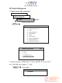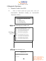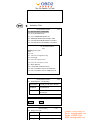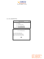
1
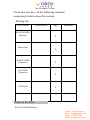
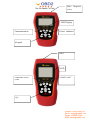
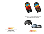
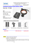
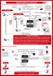
MST-100 Kia and Honda Scanner User’s Manual
Preface
Thank you for purchasing this MST-100 KIA SCANNER from Shenzhen
Zeus Technology co,ltd.
Read this document carefully so that you can use this device correctly and
safely.
After you have read this document, store it away carefully so that it is
available any time you need it.
For Safe Usage
Pls make sure you fully understand the meanings of these warnings and
cautions before reading the rest of this document.
WARNING
Always observe the following rules. Failure to do so can result in heat
generation, fire, blowout, or electrical shock.
·Do not disassemble or alter this device
·Do not connect this tester to anything with a voltage exceeding the
ratings of this device.
UOBD2.COM contact us
Email: [email protected]
Skype: UOBD2.COM
MSN: [email protected]
CAUTION Indicates an item for which incorrect
handling can lead to injury or damage to property. Under certain
conditions, more serious consequences may result.
·Do not leave this device in any location subject to excessive heat for
example in direct sunlight or inside a car on a sunny day.
·Do not touch any metal parts when connecting the device leads to to
measurement position, even when within the ratings range.
·Do not work anywhere that water could come in contact with the
equipment.
·Do not drop this tester or subject it to a strong impact.
This could cause the liquid crystal leak from inside the tester.
A rash may result if the liquid crystal comes into contact with the
skin.
If this happens, wash the skin with plenty of running water, then seek
medical attention.
·Block the wheels of the vehicle with chocks before carrying out work
such as connecting the tester cable.
Failure to do so could result in an accident.
·Do not pass the cable for this tester over the engine compartment while
the engine is running.
UOBD2.COM contact us
Email: [email protected]
Skype: UOBD2.COM
MSN: [email protected]
An accident may result in cable, test lead, or clothing becomes caught
in a belt or pulley.
·When working anywhere not be easily visible, for example under the
vehicle, always remove the key from the ignition to ensure the vehicle is
not moved.
Failure to do so could result in an accident.
·Do not work connect the scanner cables etc. while the vehicle is
running.
Doing so could result in an accident.
·When working near the engine compartment, be careful of the engine
and other high-temperature parts.
High-temperature parts can cause burns.
Table of Contents
Safety Before Use
I. Before Use
Product Configuration
UOBD2.COM contact us
Email: [email protected]
Skype: UOBD2.COM
MSN: [email protected]
Check that you have all the following standard
components before using this scanner.
·Packing list
Part Name
Illustration
KIA SCANNER
Interface
Main cable
OBD II 16PIN
Connector
KIA 20PIN
Connector
USB Cable
Qty
Remarks
1
1
1
1
1
Names of the Parts
KIA SCANNER Interface
UOBD2.COM contact us
Email: [email protected]
Skype: UOBD2.COM
MSN: [email protected]
DB15 Diagnostic
socket
LED Display
Communication
Power indicator
Keypad
DB15
LED
COMMUMICATION
LAMP
POWER LIGHT
键盘
UOBD2.COM contact us
Email: [email protected]
Skype: UOBD2.COM
MSN: [email protected]
Keypad instruction:
F1,F2,F3,F4: Function key
Shift:
▲▼
◀▶
Esc:
Enter:
Note:
·During Diagnosis, this scanner can be connected to the vehicle with the
datalink cable to run off the vehicle battery, no need other power supply
or battery.
·When the scanner is not connected to the vehicle, it can be supplied
with power via USB cable connecting to PC, or external 12V power
cable.
·It is normal for the interface to heat up during diagnosis.
Connection
This section explains how to connect the scanner to a vehicle or PC.
1. Connecting to the Vehicle
Use the main cable to connect the scanner to the vehicle (main cable
side to vehicle must be connected with 16pin or 20pin connector
according to the vehicle model).
Check the position of the vehicle-side datalink connector and choose
UOBD2.COM contact us
Email: [email protected]
Skype: UOBD2.COM
MSN: [email protected]
proper connector (16pin or 20pin)
Connected to vehicle side datalink connector
(DLC)
CAUTION
·When connecting the datalink cable to the scanner interface and the
vehicle side datalink connector, gently insert it gently straight into the
connector.
Insert the cable at a slant can break the connector pins.
·when connecting the datalink cable to the interface, make sue the
connector is in the right direction.
If you connect it the wrong way up or insert it at an angle, there is a
risk of damaging the connector terminal and causing a malfunction of the
vehicle or infter.
2. Connecting to a PC
3. Use a USB cable to connect the interface to a PC.
UOBD2.COM contact us
Email: [email protected]
Skype: UOBD2.COM
MSN: [email protected]
It is necessary to connect to PC in the following cases:
·When diagnosing the vehicle with PC version
·When updating the MST-100 software
CAUTION
·When connecting a USB cable to the interface and the PC, gently insert
the cable straight into the connector.
Inserting the cable at a slant can break the connector pins.
II Basic Operations
Starting and Ending
1. Starting
·Connect the interface and vehicle side datalink connectors
with the datalink cable.
Reference: Page () Connecting to the Vehicle (Chapter I Before
Use/Connecting)
·Turn the vehicle ignition switch ON.
·After connecting the interface to vehivle, the interface will be
automatically ON. After the opening screen is displayed, the display
automatically switches to main menu.
UOBD2.COM contact us
Email: [email protected]
Skype: UOBD2.COM
MSN: [email protected]
1.
2.
3.
4.
Kia GENERAL
VEHICLE DIAGNOSIS
SYSTEM SETUP
S/W DOWNLOAD
VIEW VERSION
1/4
2. Ending
· Turn the vehicle ignition switch OFF.
·
Disconnect the datalink cable from the vehicle side datalink
connector, the interface will be automatically OFF.
Main Menu
It displays four menu titles
Vehicle diagnosis
UOBD2.COM contact us
Email: [email protected]
Skype: UOBD2.COM
MSN: [email protected]
Pls ref. Chapter III Vehicle Diagnosis
2.1 System Setup Basic setup: setup buzzer ON/OFF
Language option
Keypad Operation: [▲ ▼] Select item, [◀ ▶] Change item, [ESC]
Cancel, [ENTER] Save.
[ENTER]
Datetime setup:
DATE:
TIME:
Keypad Operation: [◀ ▶] Select item, [▲ ▼] Change item, [ESC]
Cancel, [ENTER] Save.
3. S/W Download:
It must be connected to a PC to do software updating.
1.1 Use USB cable to connect the interface to a PC.
Run MST100_PcClient.exe on PC, click [UPDATE], will verify the
the S/N autmatically. After that, the software will be downloaded to PC,
and update the interface software.
4. View Version:
Display interface S/N, S/W version and H/W version.
Note: Here the S/W means the interface itself, not the diagnosis software.
UOBD2.COM contact us
Email: [email protected]
Skype: UOBD2.COM
MSN: [email protected]
III Vehicle Diagnosis
1. Vehicle model and system select
Main menu
Vehicle diagnosis
KIA
V25.00
V25.00
Vehicle model select:
Enter
VEHICLE DIAGNOSIS
01.
02.
03.
04.
05.
06.
07.
08.
09.
10.
1/25
CARENS
CARNIVAL/SEDONA
CEE’D
CERATO/FORTE
ENTERPRISE
JOICE
K2500/K2900
MOHAVE/BORREGO
OPIRUS/AMANTI
OPTIMA/MAGENTIS
VEHICLE DIAGNOSIS
25/25
21. SORENTO R(XM)
22. YN
23. SOUL
24. CADENZA (VG)
25. SPORTAGE (SL SLE)
Keypad Operation: [◀ ▶] Page UP/Down, [▲ ▼] UP/Down, [ESC]
Exit, [ENTER] Enter.[◀ ▶]上下页翻
Enter
Year select:
SPORTAGE (SL SLE)
1/4
01. 2011MY
UOBD2.COM contact us
Email: [email protected]
Skype: UOBD2.COM
MSN: [email protected]
Enter
System select:
2011MY
01.
02.
03.
04.
05.
06.
07.
08.
09.
10.
1/14
4 WHEEL DRIVE (4WD)
AHLS
AUTOMATIC TRANSAXLE
ANTI-LOCK BRAKE SYSTEM
BODY CONTROL MODULE
ELEC. POWER STEERING
ENGINE (GASOLINE)
ENGINE (DIESEL)
FULL AUTO AIRCON
IMMOBILIZER
Enter
ENGINE (GASOLINE)
01.
02.
03.
04.
05.
06.
Enter
1/6
LEAD 2.0L ALL
LEAD 2.4L ALL
UNLEAD 2.0L EOBD
UNLEAD 2.0L GEN
UNLEAD 2.4L EOBD
UNLEAD 2.4L GEN
Diagnostic connector suggest
LEAD 2.0L ALL
1/6
01. OBD-II 16PIN CONNECTOR
Enter
Diagnosis function
LEAD 2.0L ALL
01.
02.
03.
04.
05.
1/5
DIAGNOSTIC TROUBLE CODES
ERASE
CURRENT DATA
ACTUATION TEST
ECU INFORMATION
[Procedure 1∶Model and system select submenu
enter/exit process]
UOBD2.COM contact us
Email: [email protected]
Skype: UOBD2.COM
MSN: [email protected]
2. Diagnostic Functions:
2.1
Diagnostic Trouble Codes (DTC)
Refer to Vehicle model and system select, select [01.
2.2
DIAGNOSTIC TROUBLE CODES] [01. DIAGNOSTIC
TROUBLE CODES]
LEAD 2.0L ALL
01.
02.
03.
04.
05.
Enter
1/5
DIAGNOSTIC TROUBLE CODES
ERASE
CURRENT DATA
ACTUATION TEST
ECU INFORMATION
Read diagnostic trouble codes
DIAGNOSTIC TROUBLE CODE
1/16
P0100 MAF CIRCUIT MALFUNCTION
P0101 AFS-RANGE/PERFORMANCE
P0102 MAF CIRCUIT LOW INPUT
2.2. Erase DTC
P0103 MAF CIRCUIT HIGH INPUT
P0104
Select [02. Erase]
P0105 MAP SENSOR CIRCUIT MAL.
LEAD 2.0L ALL
1/5
P0106 MAP SNSR CIR.R/P PROBLEM
01. DIAGNOSTIC TROUBLE CODES
P0107 MAP SNSR CIR.LOW INPUT
02. ERASE
P0108 MAP SNSR CIR.HIGH INPUT
03. CURRENT DATA
P0109
04. ACTUATION TEST
05. ECU INFORMATION
Enter
Erase all the DTCs read
LEAD 2.0L ALL
2/5
CLEAR DIAGNOSE FAULT CODE
Eras success
OK
UOBD2.COM contact us
Email: [email protected]
Skype: UOBD2.COM
MSN: [email protected]
2.3 Current Data
LEAD 2.0L ALL
01.
02.
03.
04.
05.
Enter
1/5
DIAGNOSTIC TROUBLE CODES
ERASE
CURRENT DATA
ACTUATION TEST
ECU INFORMATION
Current data option
DS SELECT ID
• ABTTERY VOLTAGE
• IGNITION VOLTAGE
ENGINE SPEED
TARGET IDLE SPEED
MAP SENSOR VOLTAGE MAP
INTAKE MANIFOLD PRESS
WATER TEMP. SENSOR
WATER TEMPERATURE
INTAKE AIR TEMPERATURE
SELECT
2/09
SLT ALL
Keypad Operation: 按键操作
ACTUATION TEST
LEAD 2.0L ALL
01.
02.
03.
04.
05.
1/5
DIAGNOSTIC TROUBLE CODES
ERASE
CURRENT DATA
ACTUATION TEST
ECU INFORMATION
UOBD2.COM contact us
Email: [email protected]
Skype: UOBD2.COM
MSN: [email protected]
Enter
Actuation Test
ACTUATION TEST
1/20
01. DIAGNOSTIC LAMP(MIL)
02. FUEL PUMP RELAY
03. A/C COMPRESSOR RELAY
04. IMMOBILIZER INDICATOR LAMP
05. FAN MOTOR HIGH SPEED CONTRO
06. FAN MOTOR LOW SPEED CONTROL
07. MAIL RELAY
ACTUATION TEST
08. CANISTER PURGE VALVE
1/20
09. OIL CONTROL VALVE-INTAKE BA
01. diagnostic light
10. OIL CONTROL VALVE-EXHAUST B
02. FPR
03. The A/C compressor relay
04. Fixet light
05. Fan motor speed control
06. Fan motor low speed control
07. MAIL RELAY
08. CANISTER PURGE VALVE
09. OIL CONTROL VALVE-INTAKE BA
10. OIL CONTROL VALVE-EXHAUST B
ACTUATION TEST
01. DIAGNOSTIC LAMP(MIL)
1/20
DURATION
UNTIL [STOP] KEY PRESS
METHOD
ACTIVATION
CONDITION
IG. KEY
RUNNING
ON,
ENGINE
PRESS [START], IF YOU ARE READY
START
STOP
driven testing
02. Diagnostic light
1/20
Time
Click [STOP]
Methord
activate
running
IG. Star key, star engine
UOBD2.COM contact us
Email: [email protected]
Skype: UOBD2.COM
MSN: [email protected]
2.5. ECU INFORMATION
LEAD 2.0L ALL
01.
02.
03.
04.
05.
1/5
DIAGNOSTIC TROUBLE CODES
ERASE
CURRENT DATA
ACTUATION TEST
ECU INFORMATION
ECU INFORMATION
CAL NUM: D23234267890
ECU S/W NUM: E23234267890
BOOT S/W NUM: F23234267890
OK
UOBD2.COM contact us
Email: [email protected]
Skype: UOBD2.COM
MSN: [email protected]