1
JTLS Document 17
JTLS
Version Description Document
March 2008
U.S. Joint Forces Command
Joint Warfighting Center
116 Lake View Parkway
Suffolk, VA 23435-2697
JOINT THEATER LEVEL SIMULATION
(JTLS 3.3.0.0)
March 2008
JTLS Document 17
ABSTRACT
This JTLS Version Description Document (VDD) describes Version 3.3.0.0 of the configured
software suite identified as the Joint Theater Level Simulation (JTLS). JTLS 3.3.0.0 is a Major
release.
As a Major release, JTLS 3.3.0.0 includes a modified and enhanced Standard Database, as well as
extensive model functionality changes implemented as Enhancement Change Proposals (ECPs).
These ECPs are described in Chapter 2. Chapter 3 of this document describes the code modifications
that represent corrections to Software Trouble Reports (STRs). The remaining outstanding STRs are
described in Chapter 4.
This publication is updated and revised for each version release of the JTLS model. User corrections,
additions, or constructive recommendations for improvement must include justification and be
referenced to specific sections, pages, and paragraphs. Submissions must be written in Model Change
Request (MCR) format and forwarded to:
JTLS Configuration Management Agent
JFCOM/JWFC
116 Lake View Parkway
Suffolk, VA 23435-2697
Copyright 2008, ROLANDS & ASSOCIATES Corporation
JTLS 3.3.0.0
iii
Version Description Document
JTLS Document 17
March 2008
[Blank Page]
Version Description Document
iv
JTLS 3.3.0.0
March 2008
JTLS Document 17
TABLE OF CONTENTS
1.0 INTRODUCTION
1.1 SCOPE .......................................................................................................................... 1-1
1.2 INVENTORY OF MATERIALS ................................................................................. 1-1
1.2.1 Obsolete/Outdated Documents ............................................................................ 1-1
1.2.2 Unchanged Documents ........................................................................................ 1-1
1.2.3 Updated Documents ............................................................................................. 1-2
1.2.4 New Documents ................................................................................................... 1-2
1.2.5 Released Databases .............................................................................................. 1-3
1.3 INTERFACE COMPATIBILITY ................................................................................ 1-4
1.3.1 Support Software ................................................................................................. 1-4
1.3.2 HLA Compliance ................................................................................................. 1-5
1.3.3 JTLS Operational Interface (JOI) ........................................................................ 1-6
1.3.4 JTLS Air Tasking Order Translator (ATO-T) ..................................................... 1-6
1.4 INSTALLATION CONSIDERATIONS ...................................................................... 1-7
1.5 DATABASE MODIFICATIONS ................................................................................. 1-7
1.5.1 Graphic Symbols Update .................................................................................... 1-7
1.5.2 Database Upgrade ................................................................................................ 1-8
1.5.3 Standard Database Data Elements ....................................................................... 1-9
1.5.4 Standard Database Changes ............................................................................... 1-20
1.6 NSTALLATION NOTES ........................................................................................... 1-22
1.6.1 Installation Instructions ...................................................................................... 1-22
1.6.2 Oracle Compatibility and Installation ................................................................ 1-23
2.0 ENHANCEMENT CHANGE PROPOSALS
2.1 JTLS-0030 FRIENDLY NAVAL GUNFIRE SUPPORT ............................................ 2-1
2.1.1 Summary of Model Change Request ................................................................... 2-1
2.1.2 Design Summary .................................................................................................. 2-1
2.2 JTLS-0064 KNOTS AS NAVAL DEFAULT SPEED UOM ...................................... 2-3
2.2.1 Summary of Model Change Request ................................................................... 2-3
2.2.2 Design Summary .................................................................................................. 2-3
2.3 JTLS-0126 NAVAL MINE WARFARE ...................................................................... 2-3
2.3.1 Summary of Model Change Request ................................................................... 2-3
2.3.2 Design Summary .................................................................................................. 2-4
2.4 JTLS-0132 PERCEIVED NAVAL COURSE AND SPEED ....................................... 2-5
2.4.1 Summary of Model Change Request ................................................................... 2-5
2.4.2 Design Summary .................................................................................................. 2-6
2.5 JTLS-0239 MULTIPLE TARGETABLE WEAPON HULL HITS ............................. 2-6
2.5.1 Summary of Model Change Request ................................................................... 2-6
2.5.2 Design Summary .................................................................................................. 2-7
2.6 JTLS-2005-1480 LIFEBOAT REPRESENTATION ................................................... 2-8
JTLS 3.3.0.0
v
Version Description Document
JTLS Document 17
March 2008
2.6.1 Summary of Model Change Request ................................................................... 2-8
2.6.2 Design Summary .................................................................................................. 2-9
2.7 JTLS-2005-1537 ELS SCENARIO DATA CONSTRUCTION ................................ 2-10
2.7.1 Summary of Model Change Request ................................................................. 2-10
2.7.2 Design Summary ................................................................................................ 2-11
2.8 JTLS-2006-1646 PROVIDE TADIL-J DATA ........................................................... 2-12
2.8.1 Summary of Model Change Request ................................................................. 2-12
2.8.2 Design Summary ................................................................................................ 2-13
2.9 JTLS-2006-1889 ENTITY VIEWER ......................................................................... 2-14
2.9.1 Design Summary ................................................................................................ 2-14
2.10 JTLS-2007-2001 MAGICALLY EXPEND WEAPONS ......................................... 2-14
2.10.1 Summary of Model Change Request ............................................................... 2-14
2.10.2 Design Summary .............................................................................................. 2-15
2.11 JTLS-2007-2048 TRANSPARENCY SLIDER ....................................................... 2-15
2.11.1 Summary of Model Change Request ............................................................... 2-15
2.11.2 Design Summary .............................................................................................. 2-15
2.12 JTLS-2007-2050 INTERACTIVE EVENT RECORD AND REPLAY ................. 2-16
2.12.1 Summary of Model Change Request ............................................................... 2-16
2.12.2 Design Summary .............................................................................................. 2-16
2.13 JTLS-2007-2069 JAVA 6.0 SUPPORT ................................................................... 2-18
2.13.1 Summary of Model Change Request ............................................................... 2-18
2.13.2 Design Summary .............................................................................................. 2-19
2.14 JTLS-2007-2086 JTLS SYMBOL DATABASE INTEGRATION ....................... 2-19
2.14.1 Summary of Model Change Request ............................................................... 2-19
2.14.2 Design Summary .............................................................................................. 2-19
2.15 JTLS-2007-2122 CHANGE COMBAT SYSTEM MAINTENANCE TIME .......... 2-20
2.15.1 Summary of Model Change Request ............................................................... 2-20
2.15.2 Design Summary .............................................................................................. 2-20
2.16 JTLS-2007-2177 EXPAND COMMAND LEVEL REPRESENTATION .............. 2-21
2.16.1 Summary of Model Change Request ............................................................... 2-21
2.16.2 Design Summary .............................................................................................. 2-21
2.17 JTLS-2007-2181 PROPERLY REPORT JCATS-OWNED SUPPLIES ................. 2-23
2.17.1 Summary of Model Change Request ............................................................... 2-23
2.17.2 Design Summary .............................................................................................. 2-23
2.18 JTLS-2007-2188 REFLECT EXTERNAL AIR WEAPON EXPENDITURES ...... 2-23
2.18.1 Summary of Model Change Request ............................................................... 2-23
2.18.2 Design Summary .............................................................................................. 2-23
2.19 JTLS-2007-2189 SSL AND AUTHENTICATION FOR APACHE ........................ 2-24
2.19.1 Summary of Model Change Request ............................................................... 2-24
2.19.2 Design Summary .............................................................................................. 2-24
2.20 JTLS-2007-2218 DUAL AIR-TO-AIR AND AIR-TO-GROUND WEAPONS ..... 2-25
2.20.1 Summary of Model Change Request ............................................................... 2-25
2.20.2 Design Summary .............................................................................................. 2-25
Version Description Document
vi
JTLS 3.3.0.0
March 2008
JTLS Document 17
2.21 JTLS-2007-2219 JMRM ROUNDS CONVERSION ............................................... 2-27
2.21.1 Summary of Model Change Request ............................................................... 2-27
2.21.2 Design summary .............................................................................................. 2-27
2.22 JTLS-2007-2286 PROVIDE JOI TIME LATE OBJECT COUNTS ....................... 2-27
2.22.1 Summary of Model Change Request ............................................................... 2-27
2.22.2 Design Summary .............................................................................................. 2-27
2.23 JTLS-2007-2289 SDC IMPROVEMENTS .............................................................. 2-28
2.23.1 Summary of Model change Request ................................................................ 2-28
2.23.2 Design Summary .............................................................................................. 2-28
3.0 SOFTWARE TROUBLE REPORTS
3.1 INTRODUCTION ........................................................................................................ 3-1
3.2 ERRORS CORRECTED FOR THIS RELEASE ......................................................... 3-1
4.0 REMAINING ERRORS
4.1 INTRODUCTION ........................................................................................................ 4-1
4.2 REMAINING ERRORS ............................................................................................... 4-1
4.2.1 JTLS-0639 Error Determining When Engineering Task Completed .................. 4-1
4.2.2 JTLS-0695 Shadow Distance Of Zero Overriding Protection Radius ................. 4-1
4.2.3 JTLS-0696 Missions Ignoring Assigned Altitude on Egress ............................... 4-1
4.2.4 JTLS-0697 Missions On The Ground With Invalid Destination ......................... 4-2
4.2.5 JTLS-0698 Cannot Re-Activate Destroyed Targets ............................................ 4-2
4.2.6 JTLS-0699 Targets That Require An Owner Are Disassociated ......................... 4-2
4.2.7 JTLS-0700 GIAC Not Displaying Current Runway Length ............................... 4-2
4.2.8 JTLS-0701 Air Movement Report Does Not Consider Hold Points ................... 4-2
4.2.9 JTLS-0702 Mission Waiting For Delayed Mission ............................................. 4-2
4.2.10 JTLS-0703 Periodic Report Other Side Airbases Lists No Activity ................. 4-2
4.2.11 JTLS-0704 Immediate Cancel Of Air Mission in Delay Status ........................ 4-3
4.2.12 JTLS-0705 Missions Launching With Fewer Aircraft Than Available ............. 4-3
4.2.13 JTLS-0843 Error 427 ......................................................................................... 4-3
4.2.14 JTLS-0846 Naval Unit Distance Calculation .................................................... 4-3
4.2.15 JTLS-0865 Incorrect External Program Order .................................................. 4-4
4.2.16 JTLS-0869 Continue Engage Determination ..................................................... 4-4
4.2.17 JTLS-0870 Number of Air-to-Air Combat Kills Allowed ................................ 4-4
4.2.18 JTLS-0871 AC Mission Weapon Drop Determination ..................................... 4-4
4.2.19 JTLS-0906 Change ADA pE To Per-Element pE ............................................. 4-4
4.2.20 JTLS-0907 Scud-Like SSM Representation ...................................................... 4-5
4.2.21 JTLS-0908 Naval IADS Link Representation ................................................... 4-5
4.2.22 JTLS-0909 Display Moderate And Severe Attrition Level ............................... 4-5
4.2.23 JTLS-0910 HRU Patrol Intel Reports ................................................................ 4-5
4.2.24 JTLS-0911 Fire Artillery Wait Time Between Missions ................................... 4-6
4.2.25 JTLS-0929 Ship Changes Sides ......................................................................... 4-6
4.2.26 JTLS-0934 HRU Overwatch .............................................................................. 4-6
JTLS 3.3.0.0
vii
Version Description Document
JTLS Document 17
March 2008
4.2.27 JTLS-0942 Air Transport Cannot Combine Wet And Dry Supplies ................. 4-6
4.2.28 JTLS-0948 Lanchester Double Kills ................................................................. 4-7
4.2.29 JTLS-0949 Destroyed Target SITREP Strength Incorrect ................................ 4-7
4.2.30 JTLS-0950 JTLS Radius Of Effects .................................................................. 4-7
4.2.31 JTLS-0952 Air Report ....................................................................................... 4-7
4.2.32 JTLS-0953 All Sides Informed About Supply Dump Error .............................. 4-7
4.2.33 JTLS-0954 Multiple Supply Storage Targets .................................................... 4-7
4.2.34 JTLS-0955 Air Lift Drop Report Message ........................................................ 4-8
4.2.35 JTLS-0956 MPP Messages For Canceled Missions In Error ............................ 4-8
4.2.36 JTLS-0957 Can’t Take Control Of Unowned Runways .................................... 4-8
4.2.37 JTLS-0958 Withdrawing Units Cannot Destroy Supply Targets ...................... 4-8
4.2.38 JTLS-0959 Logistics Report Problem ............................................................... 4-8
4.2.39 JTLS-0960 Can’t Magic Move Airbase To Existing Airbase Location ............ 4-8
4.2.40 JTLS-0961 Group Ground Move Delayed To Lead Unit .................................. 4-9
4.2.41 JTLS-0962 Pass Unit Intelligence Does Not Include Update Information ........ 4-9
4.2.42 JTLS-0963 IMT Supply Category Line Disappears When Value Is Zero ......... 4-9
4.2.43 JTLS-0964 Reporting Bridge Damage .............................................................. 4-9
4.2.44 JTLS-0965 Error In Time Report For SET SP CONVOY DELAYS ............. 4-10
4.2.45 JTLS-0966 Incorrect Mission Report Locations .............................................. 4-10
4.2.46 JTLS-0967 Fire Mission Not Deleted From GENIS ....................................... 4-10
4.2.47 JTLS-0968 Inconsistency Between Regular Run And Pusher ........................ 4-10
4.2.48 JTLS-0969 Changing Mission On Alert .......................................................... 4-10
4.2.49 JTLS-0970 Availability Of Aircraft ................................................................. 4-11
4.2.50 JTLS-0971 Ship Continuous Tracking Not Working ...................................... 4-11
4.2.51 JTLS-0972 Air Mission Find In Middle Of Ocean .......................................... 4-11
4.2.52 JTLS-0973 Periodic Report Air Supplies And Fuel Not Correct .................... 4-11
4.2.53 JTLS-0974 Submarine Detection By Ground Sensors .................................... 4-11
4.2.54 JTLS-0975 GDS Target Update Error ............................................................. 4-11
4.2.55 JTLS-0976 Manual Pairing And Protection Radius ........................................ 4-11
4.2.56 JTLS-0977 Slightly Inaccurate Runway Length Sometimes Used .................. 4-12
4.2.57 JTLS-0978 Air Missions Don't Completely Comply With Egress .................. 4-12
4.2.58 JTLS-0979 Halted Helo Squadrons Show Mission As MOVING .................. 4-12
4.2.59 JTLS-0980 SVP Warning 22 ........................................................................... 4-12
4.2.60 JTLS-0981 Formation With No Posture .......................................................... 4-12
4.2.61 JTLS-0982 GIAC Shows HRU Mission Moving After Move Complete ........ 4-13
4.2.62 JTLS-0983 IMT/GIAC Show Insert/Extract Mission Flying .......................... 4-13
4.2.63 JTLS-0984 IMT Doesn’t Add Unit Names ..................................................... 4-13
4.2.64 JTLS-0985 PSYOP Results Multiplier ............................................................ 4-13
4.2.65 JTLS-0987 Set Periodic Report Times ............................................................ 4-13
4.2.66 JTLS-0988 Can’t Repair Naval Catapults ....................................................... 4-14
4.2.67 JTLS-0989 Controller Damaged Aircraft Not In Periodic Reports ................. 4-14
4.2.68 JTLS-0993 Weapons Report on Mission Report ............................................. 4-14
4.2.69 JTLS-0994 HRU Creation Target Requirements Assessed Incorrectly .......... 4-14
Version Description Document
viii
JTLS 3.3.0.0
March 2008
JTLS Document 17
4.2.70 JTLS-0999 Cancel Naval Mission Fails When A Unit Is Specified ................ 4-14
4.2.71 JTLS-1010 Controller Cannot MM NEUTRAL Unit Onto Formation ........... 4-14
4.2.72 JTLS-1017 Airlift Mission Problem ................................................................ 4-15
4.2.73 JTLS-1260 EMCON Order Problem Subordinates of Embarked Units .......... 4-15
4.2.74 JTLS-1328 SAM/AAA Initial Issue ................................................................ 4-15
4.2.75 JTLS-1341 Assign Multi Attack Order ............................................................ 4-15
4.2.76 JTLS-1351 Air Missions Refuel And Fly At Zero Altitude ............................ 4-16
4.2.77 JTLS-1364 ROE Setting Unstable ................................................................... 4-16
4.2.78 JTLS-1368 Orbiting OAS Assign Target ........................................................ 4-16
4.2.79 JTLS-1375 Orbit Location In Ingress Route ................................................... 4-16
4.2.80 JTLS-1376 Fuel Chits ...................................................................................... 4-16
4.2.81 JTLS-1377 Attack Posture Heading Home ...................................................... 4-16
4.2.82 JTLS-1378 Mission Refuel Chit Retrieval Button Does Not Work ................ 4-17
4.2.83 JTLS-1379 Improve Mission Splitting Capability ........................................... 4-17
4.2.84 JTLS-1380 Intercept Stopped for Refuel Chit Time ........................................ 4-17
4.2.85 JTLS-1381 Mission Stops Moving After Break-off Intercept ......................... 4-17
4.2.86 JTLS-1382 TBMCS ATO ID Problems .......................................................... 4-17
4.2.87 JTLS-1383 Alert Missions Display On COP ................................................... 4-17
4.2.88 JTLS-1384 Area, Target, And Unit Report Documentation ............................ 4-17
4.2.89 JTLS-1387 TBMCS Not Updating ATO Change Missions ............................ 4-18
4.2.90 JTLS-1390 Orbiting OAS ................................................................................ 4-18
4.2.91 JTLS-2005-1455 Changing Support Unit Via Naval Move Incorrect ............ 4-18
4.2.92 JTLS-2005-1456 Improper Formation Arrive Time Message ........................ 4-18
4.2.93 JTLS-2005-1457 Target Auto Assign Errors In Orbiting OAS ...................... 4-18
4.2.94 JTLS-2005-1458 CAS Damage Errors From Orbiting OAS .......................... 4-18
4.2.95 JTLS-2005-1459 Delay Order Not Executed Properly ................................... 4-19
4.2.96 JTLS-2005-1460 Ship Heading Inconsistency ............................................... 4-19
4.2.97 JTLS-2005-1463 Units in Combat While Embarked ...................................... 4-19
4.2.98 JTLS-2005-1464 Location Fields Allow Invalid Location Formats ............... 4-19
4.2.99 JTLS-2005-1466 Incoming Messages Not In Correct Order ........................... 4-19
4.2.100 JTLS-2005-1468 Perceived Aircraft Vectors Point In Wrong Direction ..... 4-19
4.2.101 JTLS-2005-1469 Shooting Side Has No Perception Of Shot Missile .......... 4-20
4.2.102 JTLS-2005-1471 Utilities Should Alter Group When Row Is Edited .......... 4-20
4.2.103 JTLS-2005-1475 Improper Depiction Of Unit Transported By Convoy ...... 4-20
4.2.104 JTLS-2005-1476 Aircraft Orders Allowed After JCATS Has Control ........ 4-20
4.2.105 JTLS-2005-1478 Order Lines Change Position on Map .............................. 4-20
4.2.106 JTLS-2005-1598 Strip Alert Missions Unusable In Quick Manual Pair ...... 4-21
4.2.107 JTLS-2007-2053 Red Hat Linux 3.0 Does Not Execute JTLS Components 4-21
APPENDIX A. ABBREVIATIONS AND ACRONYMS ....................................................... A-1
APPENDIX B. COMBAT SYSTEM CATEGORY DEFINITIONS........................................B-1
JTLS 3.3.0.0
ix
Version Description Document
JTLS Document 17
March 2008
APPENDIX C . VERSION 3.3 STANDARD DATABASE CHANGES..................................C-1
C.1 GENERAL MODIFICATIONS ...................................................................................C-1
C.2 NEW SDBOIF SCENARIO .........................................................................................C-2
C.3 COMBAT SYSTEM UPGRADES ..............................................................................C-2
C.4 SUPPORTING EXISTING COMBAT SYSTEMS .....................................................C-7
C.5 REMAINING ENHANCEMENTS .............................................................................C-8
C.6 VERSION 3.3.0.0 STANDARD DATABASE CHANGES ........................................C-8
Version Description Document
x
JTLS 3.3.0.0
March 2008
JTLS Document 17
1.0 INTRODUCTION
1.1 SCOPE
This JTLS Version Description Document (VDD) describes Version 3.3.0.0 of the configured
software suite identified as the Joint Theater Level Simulation (JTLS). JTLS 3.3.0.0 represents the
follow-on capability to the JTLS 3.2 series of releases.
JTLS 3.3.0.0 is a Major release that includes the Web Hosted Interface Program (WHIP), as well as
an updated Standard Database, named sdboif33, that includes a new and more realistic scenario based
on Operation Iraqi Freedom. Database modifications that were accomplished to upgrade the previous
JTLS Standard Database to this current version are summarized in this chapter. Detailed descriptions
of Enhancement Change Proposals (ECPs) implemented for this release are provided in Chapter 2.
The code maintenance modifications that represent corrections to Software Trouble Reports (STRs)
are described in Chapter 3 of this document. The remaining outstanding STRs are described in
Chapter 4.
The JTLS 3.3.0.0 release executes on the SUN/SPARC Solaris and the Red Hat Linux operating
systems.
1.2 INVENTORY OF MATERIALS
This section lists documents and software relevant to JTLS. JTLS documents can be obtained by
contacting the Configuration Management Agent (CMA) at the address listed in the Abstract on
Page iii of this document. DoD Military Standards can be obtained through the appropriate military
channels.
1.2.1 Obsolete/Outdated Documents
No documents have been removed from the JTLS documentation suite for this release.
1.2.2 Unchanged Documents
The model enhancements implemented for JTLS 3.2.0.0 are included in JTLS 3.3.0.0 and are
incorporated within the documentation provided for this release:
a.
b.
c.
d.
e.
JTLS ATOG User’s Guide (JTLS Document 02, Version 3.2.0.0)
JTLS ATOT User’s Guide (JTLS Document 03, Version 3.2.2.0)
JTLS Director’s Guide (JTLS Document 07, Version 3.2.0.0)
JTLS PPS User’s Guide (JTLS Document 13, Version 3.2.0.0)
JTLS Executive Overview (JTLS Document 08, Version 3.2.1.0)
JTLS 3.3.0.0
1-1
Version Description Document
JTLS Document 17
March 2008
1.2.3 Updated Documents
The documents listed in this section have been updated for JTLS 3.3.0.0 to reflect functional
enhancements or requirements to the JTLS system.
a.
b.
c.
d.
e.
f.
g.
h.
i.
j.
k.
l.
JTLS Analyst’s Guide (JTLS Document 01, Version 3.3.0.0)
JTLS Controller’s Guide (JTLS Document 04, Version 3.3.0.0)
JTLS Data Requirements Manual (JTLS Document 05, Version 3.3.0.0)
JTLS DDS User’s Guide (JTLS Document 06, Version 3.3.0.0)
JTLS Installation Manual (JTLS Document 09, Version 3.3.0.0)
JTLS WHIP Training Manual (JTLS Document 10, Version 3.3.0.0)
JTLS Player’s Guide (JTLS Document 12, Version 3.3.0.0)
JTLS Standard Database Description (JTLS Document 14, Version 3.3.0.0)
JTLS Software Maintenance Manual (JTLS Document 15, Version 3.3.0.0)
JTLS Technical Coordinator’s Guide (JTLS Document 16, Version 3.3.0.0)
JTLS Entity Level Server User’s Guide (JTLS Document 19, Version 3.3.0.0
JTLS Version Description Document (JTLS Document 17, Version 3.3.0.0)
1.2.4 New Documents
JTLS 3.3.0.0 includes the Entity Level Server, a program designed to independently model the
movement of entities represented by aggregate JTLS units. The JTLS ELS User’s Manual (JTLS
Document 19, Version 3.3.0.0), which describes the functional requirements and user procedures
implemented for the JTLS Entity Level Server, is provided with this release. [Change this section:
ELS is included from JTLS 3.2, but no new documents have been added.]
The JTLS Version 3.3.0.0 may be delivered either on a CD, or as a set of compressed tar files to be
downloaded. Either method includes the complete suite of software executable code and command
procedures. The following software components are included in this release:
a.
b.
c.
d.
e.
f.
g.
h.
i.
j.
k.
l.
m.
n.
Combat Events Program (CEP)
Information Management Tool (IMT)
Message Data Parser (MDP)
Scenario Initialization Program (SIP)
Interface Configuration Program (ICP)
Interface Configuration Program Login (IPCLogin)
Order Preprocessor Program (OPP)
Reformat Spreadsheet Program (RSP)
Database Development System (DDS)
Terrain Modification Utility (TMU)
Lanchester Development Tool (LDT)
ATO Generator Program (ATOG)
ATO Translator Program (ATOT)
ATO Retrieval Program (ATORET)
Version Description Document
1-2
JTLS 3.3.0.0
March 2008
JTLS Document 17
o.
p.
q.
r.
s.
t.
u.
v.
w.
x.
Convert Location Program (XCONVERT)
Count Critical Order Program (CCO)
Graphical Database Program (GDP)
HLA Interface Program (HIP)
After Action Review Client (AARC)
Scenario Data Client (SDC)
Order Entry Client (OEC)
Order Verification Tool (OVT)
JTLS Object Distribution Authority (JODA)
Web-Hosted Interface Program (WHIP) and its component programs:
1. Apache Server (APACHE)
2. JTLS XML Serial Repository (JXSR)
3. Order Management Authority (OMA)
4. Synchronized Authentication and Preferences Service (SYNAPSE)
5. Web Services Manager (WSM)
6. XML Message Service (XMS)
7. Total Recall Interactive Playback Program (TRIPP)
y. Entity Level Server (ELS)
z. JTLS Operational Interface (JOI)
[v3.2 programs removed: Template Building Tool (TBT), Message Processor Program (MPP)]
Instructions for installing JTLS 3.3.0.0 are provided in the JTLS Installation Manual. It is not
necessary to install any previous version of JTLS prior to installing JTLS 3.3.0.0. No other upgrade
beyond installation of the compressed tar files (or CD) is required. The software that is provided is a
complete release that includes all files and code required to execute JTLS.
1.2.5 Released Databases
This release includes two sample unclassified databases.
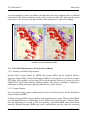
The scenario developed as Standard Database Operation Iraqi Freedom and named sdboif is a
large-scale, seven-sided scenario database reflecting the approximate starting positions of units
involved in the March 2003 invasion of Iraq. This example scenario was developed using unclassified
data sources and as a result is not completely accurate. Discrepancies with actual units and their
locations are not detrimental to the intended purpose of this database, which is to provide a
recognizable and realistic scenario that demonstrates the simulation capabilities and supports JTLS
training.
The scenario blank32 is the sdboif database with all force structure data removed. It can be used as the
foundation to build your own database.
JTLS 3.3.0.0
1-3
Version Description Document
JTLS Document 17
March 2008
1.3 INTERFACE COMPATIBILITY
1.3.1 Support Software
JTLS 3.3.0.0 requires the following versions of support software, including operating systems,
compilers, scripting utilities, database tools, transfer protocols, and display managers.
a. Operating system for the model (one of the following):
1. Solaris 8 for use on Sun/SPARC Workstations
2. Solaris 9 for use on Sun/SPARC Workstations
3. Red Hat Linux Enterprise Edition Version 4.0 (ES), 32-bit or 64-bit architecture.
Some JTLS components will not execute under Red Hat Linux Enterprise
Edition Version 3.0 (ES). Therefore, model support for this OS version has been
discontinued. However, Linux Enterprise Edition 3.0 (WS) may be used on
client workstations to execute the WHIP.
b. Operating system for workstations (one of the following):
1. Solaris 8 for use on Sun/SPARC Workstations
2. Solaris 9 for use on Sun/SPARC Workstations
3. Red Hat Linux Enterprise Edition Version 3.0 (WS)
4. Red Hat Linux Enterprise Edition Version 4.0 (WS), 32-bit or 64-bit architecture.
5. Windows 2000, XP Professional, or Vista
Although Solaris 8 and Solaris 9 are fully supported to operate JTLS
workstations, the Java-based Web-Hosted Interface Program (WHIP) is
noticeably more efficient on Linux-based or Windows-based operating system
machines.
c. Operating system for Support Software, such as HIP, SIP, etc:
1. Solaris 8 for use on Sun/SPARC Workstations (excepting all HLA programs)
2. Solaris 9 for use on Sun/SPARC Workstations
3. Red Hat Linux Enterprise Edition Version 4.0 (ES)
d. Java Version 1.5 or later is required for all platforms. Java 1.5 or 1.6 may be used to
support WHIP workstations.
e. JTLS database tools require the use of an Oracle database server and the Oracle Form/
Reports Developer 6i client/server runtime (with patchset 18 or later). Refer to Section
1.6.2, Oracle Compatibility and Installation of this chapter for additional installation
details.
f. Windows software, X11R5 server, Motif 1.2 Library, Motif Window Manager: These
items are included as part of Solaris 8 or 9 and Linux 4.0.
g. Adobe Acrobat Reader Version 4.0.5 or later, is required to read the delivered JTLS
documentation. The JTLS 3.3.0.0 tar file (or CD) includes the freeware version of Acrobat
Reader.
Version Description Document
1-4
JTLS 3.3.0.0
March 2008
JTLS Document 17
h. TCP/IP is required for inter-process communication between the JODA data server and all
user interface programs. The version of TCP/IP included with Solaris 8 or 9, and Red Hat
Linux ES/WS 4.0 is sufficient.
i. The Perl script language is used by the JTLS system and game setup scripts. The version
of Perl included with Solaris 8 or 9, or Red Hat Linux ES/WS 4.0 is sufficient. The Perl
program is typically located in the /usr/bin directory. If Perl is installed in a another
location, a link should be created from the /usr/bin directory to this program.
j. KDE Desktop support has been added to JTLS Version 3.3.0.0. Support of the GNOME
desktop is continuing, and use of the KDE environment is optional. Details regarding the
installation and use of KDE are provided in Section 4.4.3.2 of the JTLS Installation
Manual.
k. SIMSCRIPT II.5 (SIMSCRIPT to C) translator/compiler: SIMSCRIPT is required for
recompiling JTLS code. It is not necessary to have a SIMSCRIPT compiler to execute
JTLS, because all JTLS software executables are statically linked with the SIMSCRIPT
libraries. The compiler is needed only if you are a U.S. Government organization that can
obtain source code and plan to re-compile JTLS SIMSCRIPT code. To obtain a
SIMSCRIPT compiler, contact CACI Inc. The following SIMSCRIPT II.5 versions are
recommended for each platform:
1. 32-bit SUN Solaris: version 3.0.3
2. 32-bit Red Hat Linux: version 3.4
3. 64-bit Red Hat Linux: version 3.5
l. ANSI C Compiler: It is not necessary to use a C compiler to execute JTLS. This compiler
is needed only if you are a U.S. Government organization that can obtain source code and
plan to re-compile any JTLS software program. If you need a C compiler, the following
versions will suffice:
1. SUN Solaris: ANSI C 5.2 or later
2. Linux: C Compiler as delivered with Red Hat Linux ES 4.0
m. C++ Compiler: It is not necessary to use a C++ compiler to execute JTLS. This compiler
is needed only if you are a U.S. Government organization that can obtain source code and
intend to re-compile any of the JTLS HLA software programs. If you need a C++
compiler, these versions are sufficient:
1. SUN Solaris: ANSI C++ 5.2 or later
2. Linux: C++ Compiler delivered with Red Hat Linux ES 4.0
1.3.2 HLA Compliance
The JTLS 3.3.0.0 release is fully High Level Architecture (HLA) compliant, and includes all the
programs required to run JTLS in an HLA mode on any operating system listed in Item c of Section
1.3.1, Support Software.
The HLA RTI (Run Time Infrastructure) executive program (rtiexec) recommended for use with this
release is RTI-NG-Pro-v4.0. However, this program is not included in the JTLS 3.3.0.0 delivery.
Users may obtain a full installation package of this RTI software from the vendor, Raytheon Virtual
JTLS 3.3.0.0
1-5
Version Description Document
JTLS Document 17
March 2008
Technology Corporation, by contacting their Web site at http://www.virtc.com. For information about
executing the HLA RTI Executive and other HLA-related software, refer to the appropriate HLA
documentation and user guides.
1.3.3 JTLS Operational Interface (JOI)
JTLS exercises conducted by the United States Government have required data feeds to real-world
Control, Communications, Computers, and Intelligence (C4I) systems. The JOI is designed to
provide a configuration-managed capability to covey current JTLS force status information to these
systems. This capability allows all JTLS Units and Air Missions to be passed via OTH-Gold message
format to the US Global Command Control System (GCCS) or to any other system that accepts OTHGold messages by means of a TCP/IP socket connection.
The JOI is a JTLS Object Distribution Authority (JODA) client that has the capability to easily start
and stop the feed of these OTH-Gold messages according to the status of the JTLS game and is able
to alter the naming data passed to the real-world systems. Consequently, any database object naming
errors can be corrected independently of the model to allow the exercise audience to view correct
names while monitoring the real-world system that is populated by the JOI. The JOI has a complete
checkpointing capability and can be restarted from any of its checkpoint files without losing
information.
Chapter 15 of the JTLS Technical Coordinator’s Guide describes procedures for using the JOI and
how the program obtains information required to properly fill the OTH-Gold messages. Information
about operating the Global Command and Control System (GCCS) is not included. The content and
format specifications of each message file that the JOI accesses are described in Chapter 34 of the
JTLS Software Maintenance Manual.
1.3.4 JTLS Air Tasking Order Translator (ATO-T)
The ATO-T executes in two modes, named basic and advanced for the purpose of this description.
The ATO-T requires libraries from Simscript and Oracle to run in either mode. The basic mode of the
ATO-T reads and processes Air Tasking Orders in USMTF format, as well as Air Mission data
prepared using an Excel spreadsheet and delivered in comma-delimited format. The output from the
the ATO-T at the basic level consists of ASCII order files that may be read into the CEP using the
READ ORDER FILE order.
The advanced ATO-T mode reads Air Tasking Orders and Air Mission data in the same formats as the
basic mode. However, this mode writes the orders directly to Oracle tables for error checking and for
input directly to the CEP using the Order Entry Client (OEC). Each order written into the Oracle
tables specifies a time the order is scheduled for submission to the CEP. The OEC continuously
monitors the Oracle tables and performs a final error verification at this specified time before
submitting the order.
Version Description Document
1-6
JTLS 3.3.0.0
March 2008
JTLS Document 17
The Simscript and Oracle library support required by both ATO-T modes are obtained separately. The
Simscript support is now provided with each JTLS release. The necessary Simscript libraries are
released in the bin_support directory for 32 bit Linux. To run the basic mode, users must obtain,
install, and configure the most current Oracle Runtime client from Rolands & Associates
Corporation. To run the advanced mode, users must have access to an Oracle server configured for
iAS.
1.4 INSTALLATION CONSIDERATIONS
The procedures for installing JTLS 3.3.0.0 depend on the hardware configuration provided at the
installation site. All installation considerations are addressed in the JTLS Installation Manual.
1.5 DATABASE MODIFICATIONS
This release includes a completely new demonstration database, named sdboif, that provides
enhanced, realistic support of real-world operations. Additionally, significant database changes were
implemented in conjunction with the upgrade from JTLS Version 3.1.0.0 to Version 3.2.0.0. The
following sections provide a detailed description of these changes. Data parameter adjustments
implemented for JTLS 3.3.0.0 are described in Appendix C, VERSION 3.3.0.0 STANDARD
DATABASE CHANGES, Section C.6.
1.5.1 Graphic Symbols Update
Updating the graphic symbol definitions for your JTLS scenario is required before the database is
upgraded to Version 3.2. To upgrade the symbol file for a scenario, use this procedure to run the
JSyms application and resave the symbols:
1. Run JSyms for the scenario by typing this command: jsyms <scenario_name>.
2. Before JSyms starts, this dialog message appears: "Your symbol files need to be
upgraded. Select File Save to upgrade." At this point, you will not need to make any
modifications to the symbol file. JSyms will perform the upgrade when the symbols are
saved. You can bypass the upgrade process by exiting JSyms without saving.
3. Select File > Save and exit JSyms.
Note: JTLS 3.2 graphic symbols have an Organization Type field that is not present in Version 3.1.
After this required upgrade process is complete, each symbol will be assigned a default
Organization Type of UNK.
JTLS 3.3.0.0
1-7
Version Description Document
JTLS Document 17
March 2008
1.5.2 Database Upgrade
The generic JTLS database upgrade feature of the Database Development System (DDS), known as
the JTLS Database Modify process, is accessed by a sequence of three JTLS Menu options: 1.
Prepare or Alter a Scenario Database > 1. Access the Database Development System Menu > 2.
Access an Existing Database. This upgrade feature must be used to upgrade the JTLS Standard
Database from Version 3.1 to Version 3.2.0.0
Oracle Database Server version 9.2.0.8 or later must be used to execute the
Database Modify process while upgrading the JTLS Standard Database from
any previous version to Version 3.3.0.0. The modification process will fail if
performed using earlier Oracle DB versions.
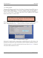
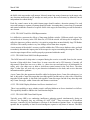
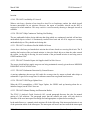
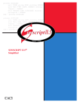
When the user selects and accesses a database that does not conform to the Standard Database 3.2
format, a Warning dialog box (Figure 1.1) queries the JTLS user to begin the upgrade process.
Figure 1.1 Starting the Database Upgrade
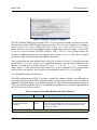
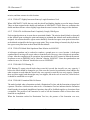
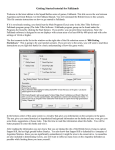
Selecting the Yes option executes a separate process, entitled Modifying Your JTLS Database, that
determines the existing format of the selected database, begins the upgrade, and displays its progress
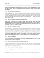
The database upgrade is successfully completed when the message shown in Figure 1.2 is displayed.
The terminal window should then be closed.
Version Description Document
1-8
JTLS 3.3.0.0
March 2008
JTLS Document 17
Figure 1.2 Database Upgrade Completed
The JTLS Database Modify process for the JTLS 3.1 series of releases includes an interactive feature
that requires user input while the upgrade process executes. This interactive upgrade process must be
used to modify your scenario database from JTLS version 3.0 or earlier to JTLS Version 3.3.0.0.
Ensure that you review the corresponding database modification section of Chapter 1 of the JTLS
Version Description Document for JTLS versions 3.1.0.0, 3.1.1.0, or 3.1.2.0, which describes the
interactive modification process for the upgrade from Version 3.0 to 3.1. This process requires
specific user input, which is described and illustrated in detail.
After your database has been modified from Version 3.0 or earlier to Version 3.3.0.0 and downloaded
to ASCII files, a successive scenario load is required to properly create the check constraints in the
database to include the new illegal character set ( space, ", #, &, @, /, {, }, <, >, ’ ). Unit names,
Target names, or other object names that contain any of these characters will be automatically
removed from your database. These symbols are incompatible with the JTLS 3.3.0.0 WHIP.
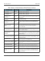
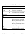
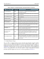
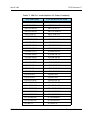
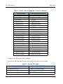
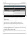
1.5.3 Standard Database Data Elements
The ECPs implemented for JTLS 3.3.0.0 have required the addition, deletion, or modification of
various data parameters in the JTLS Standard Database. The description and use of these variables to
suppoer the functional changes are described in Chapter 2 of this document and summarized below in
Table 1. Detailed descriptions of the new or modified data parameters are provided in Appendix B of
the JTLS Data Requirements Manual.
Table 1.Summary of Standard Database OIF Data Elements
VARIABLE NAME
CHANGE
DESCRIPTION
JTLS-0097 Guided Missiles Close To Shore
TW TERRAIN EFFECT
PERCENT
Added
This parameter represents the percentage of the value of TT SHIP
DETECTION MODIFIER that should be applied to the Targetable
Weapon’s Probability of Hit when the weapon is aimed at a ship
located close to shore.
JTLS-0126 Naval Mine Warfare
JTLS 3.3.0.0
1-9
Version Description Document
JTLS Document 17
March 2008
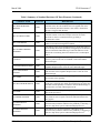
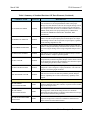
Table 1.Summary of Standard Database OIF Data Elements (Continued)
VARIABLE NAME
CHANGE
DESCRIPTION
AC WATER MINEFIELD
CLEAR TIME
Deleted
An aircraft’s ability to clear mines will instead be determined by its
AC MINE CLEAR CAPABILITY.
AC LAND MINEFIELD
CLEAR TIME
Deleted
An aircraft’s ability to clear mines will instead be determined by its
AC MINE CLEAR CAPABILITY.
SUP TIME TO LAY
MINEFIELD
Deleted
The time to lay a minefield will instead be a combination of SUP
MINE LAY PREPARE TIME and the time required to emplace each
individual mine.
SUP TIME TO CLEAR
MINEFIELD
Deleted
No replacement concept.
SUP MFT NDT KILLS BY
MINEFIELD
Deleted
Damage caused by minefields uses revised Naval Damage logic
developed to support JTLS-0239 Multiple Targetable Weapon Hull
Hits.
LOAD ASSIGNMENT
ARRAY
Modified
A new Mine Laying row is added to this array and the former Mining
row is designated as the Mine Clearing row. The database
modification procedure copies the current Mining mission data to the
new row of this table.
TW TIME PER ROUND
Modified
This attribute of the Targetable Weapon permanent entity has
different meanings and relationships to other attributes for various
types of Targetable Weapons.
TW DZ EMPLACE
MODIFIER
Added
If Targetable Weapon I is a mine being laid or emplaced in Depth
Zone J, this data parameter is used to modify or alter the TW TIME
PER ROUND data used to represent the baseline time to emplace the
Targetable Weapon.
MFT TERRAIN ELIGIBILITY
Added
This attribute of the Minefield Type permanent entity indicates
whether the Minefield Type represents a LAND, WATER, or ANTIINVASION minefield.
MFT DEPTH TYPE
Added
This attribute of the Minefield Type permanent entity indicates the
depth setting options for this Minefield Type.
MFT MAX CABLE LENGTH
Added
This attribute of the Minefield Type permanent entity represents the
maximum length that the attached mine can be positioned above its
anchor or base.
MFT MINIMUM DEPTH
Added
This attribute of the Minefield Type permanent entity represents the
minimum depth at which mines in the minefield can be placed.
MFT MAXIMUM DEPTH
Added
This attribute of the Minefield Type permanent entity represents is
the maximum depth at which mines in the minefield can be placed.
Added
This attribute of the Minefield Type permanent entity represents the
maximum value, after all modifiers have been applied, that can be
used to randomly determine whether a mine within a minefield of
this type is detected.
MFT MAX PROB MINE
DETECT
Version Description Document
1-10
JTLS 3.3.0.0
March 2008
JTLS Document 17
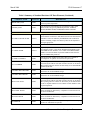
Table 1.Summary of Standard Database OIF Data Elements (Continued)
VARIABLE NAME
CHANGE
DESCRIPTION
Added
This attribute of the Minefield Type permanent entity represents the
maximum value, after all modifiers have been applied, that can be
used to randomly determine whether a mine within a minefield of
this type is triggered and detonates.
MFT NO DETECT TIME
Added
This attribute of the Minefield Type permanent entity represents the
maximum amount of time that can elapse between successful
detections of mines in a minefield of this type during a
reconnaissance search.
MFT LANE WIDTH
Added
This attribute of the Minefield Type permanent entity represents the
width of a cleared lane through the minefield.
MFT DZ MINE TRIGGER
MODIFIER
Added
This attribute of the compound Minefield Type, Depth Zone entity is
used to modify the baseline probability of triggering an encountered
mine in a minefield of Minefield Type I when the difference in the
depth of the encountering Naval Unit and the mine is within Depth
Zone J.
TG DEPTH
Added
This attribute of a Target temporary entity holds the depth of the
explosive portion of the mine for WATER or ANTI-INVASION
Minefield Targets.
TG TARGETABLE WEAPON
Added
This attribute of the Target temporary entity holds the name of the
Targetable Weapon used to create the water Minefield Target.
EE TG TARGETABLE
WEAPON
Added
This attribute of the a Create Target External Event temporary entity
holds the name of the Targetable Weapon used to create the water
Minefield Target.
MSC NAME
Added
This attribute of the Mine Search Capability permanent entity holds
the text name of the capability.
MFT MAX PROB MINE
TRIGGER
MSC MFT DZ PROB DETECT Added
This attribute of the Mine Search Capability, Minefield Type, and
Depth Zone compound entity holds the probability that an object that
uses Mine Search Capability I can detect a mine in Minefield Type J
when the mine is located within Depth Zone K.
SSL NAME
Added
This attribute of the Ship Speed Level permanent entity holds the text
name of the speed level
SSL MINIMUM SPEED
Added
This attribute of a record held by the Ship Speed Level permanent
entity holds the slowest speed at which the other data held for this
entity applies.
SSL MINE DETECT
MODIFIER
Added
This variable attribute of a speed record held by a Ship Speed Level
permanent entity holds the modifier to the probability of detecting a
mine for a ship whose speed is within the Ship Speed Level.
SSL MINE TRIGGER
MODIFIER
Added
This attribute of a speed record held by a Ship Speed Level
permanent entity holds the modifier to the probability of triggering a
mine for a ship whose speed is within the Ship Speed Level.
JTLS 3.3.0.0
1-11
Version Description Document
JTLS Document 17
March 2008
Table 1.Summary of Standard Database OIF Data Elements (Continued)
VARIABLE NAME
CHANGE
DESCRIPTION
SSL PROB HIT MODIFIER
Added
[A new SSL entity is introduced to support this design. JTLS-0239
Multiple Targetable Weapon Hull Hits uses the same SSL concept
and describes the new speed record attribute SSL PROB HIT
MODIFIER. The description of this new attribute is contained within
JTLS-0239 Multiple Targetable Weapon Hull Hits.]
SUP MINE LAY PREPARE
TIME
Added
This attribute of the Ship Unit Prototype permanent entity holds the
time a ship of this SUP must remain after it has arrived in the mined
hex, before it can begin to lay mines.
SUP MINE SEARCH
CAPABILITY
Added
This attribute of the Ship Unit Prototype (SUP) permanent entity
holds the MSC NAME of a Mine Search Capability that should be
used for Naval Units that use this SUP.
SUP MINE CLEAR
CAPABILITY
Added
This attribute of the Ship Unit Prototype (SUP) permanent entity
holds the MCC NAME of the Mine Clear Capability that a Naval
Unit using this SUP.
SUP SHIP SPEED LEVEL
Added
This attribute of the Ship Unit Prototype permanent entity holds the
name of the SSL entity that is used to define the effect of speed on the
probability that the ship will detect mines or trigger mines.
SUP MFT PROB MINE
TRIGGER
Added
This attribute of the compound Ship Unit Prototype, Minefield Type
entity is the baseline probability that a ship using Ship Unit Prototype
I will trigger an encountered mine in Minefield Type J.
Added
This attribute of the Mobility Counter-Mobility Prototype permanent
entity holds the default speed that a ship will assume when in enters
the hex where it has been ordered to lay mines, and is also the
maximum speed at which a ship whose Faction uses the MCP may
lay mines.
Added
This attribute of the Mobility Counter-Mobility Prototype permanent
entity holds the default speed that a ship will assume when in enters
the hex where it has been ordered to perform an exploration search
for mines.
Added
This attribute of the Mobility Counter-Mobility Prototype permanent
entity holds the default speed that a ship will assume when in enters
the hex where it has been ordered to perform a reconnaissance search
for mines.
MCP DEFAULT CLEAR MINE
Added
SPEED
This attribute of the Mobility Counter-Mobility Prototype permanent
entity holds the default speed that a ship will assume when in enters
the hex where it has been ordered to clear mines, whether a number
of lanes or all mines.
MCC NAME
This attribute of the Mine Clear Capability permanent entity holds
the text name of the capability.
MC DEFAULT LAY MINE
SPEED
MCP DEFAULT EXPLORE
MINE SPEED
MCP DEFAULT RECON
MINE SPEED
Added
Version Description Document
1-12
JTLS 3.3.0.0
March 2008
JTLS Document 17
Table 1.Summary of Standard Database OIF Data Elements (Continued)
VARIABLE NAME
CHANGE
DESCRIPTION
Added
This attribute of the compound Mine Clear Capability, Minefield
Type, Depth Zone entity holds the number of mines that a ship whose
Ship Unit Prototype uses Mime Clear Capability I can clear in one
day in a minefield of Minefield Type J when the difference in the
depth between the Naval Unit and the mine is within Depth Zone K.
IIP VISUAL MSC ENTITY
Added
This attribute of the Intel Information Prototype (IIP) permanent
entity holds the MSC NAME of the default Mine Search Capability
that will be used by objects that use this IIP when they are conducting
visual detections of mines within a minefield.
SB MFT PROB MINE
TRIGGER
Added
This attribute of the Small Boat, Minefield Type compound entity is
the baseline probability that a Small Boat of type I will trigger an
encountered mine (cause it to explode) in Minefield Type J.
SB SHIP SPEED LEVEL
Added
This attribute of the Small Boat permanent entity holds the name of
the SSL entity that is used to define the effect of speed on the
probability that the Small Boat will detect mines or trigger mines.
AC MINE SEARCH
CAPABILITY
Added
This attribute of the Aircraft Class permanent entity holds the MSC
NAME of a Mine Search Capability that should be used for Air
Missions that have these type of aircraft.
AC MINE CLEAR
CAPABILITY
Added
This attribute of the Aircraft Class permanent entity holds the MCC
NAME of the Mine Clear Capability that an Air Mission with this
type of aircraft should used when it is assigned a mine clearing
mission.
AC MINE EXPLORE AREA
Added
This attribute of the Aircraft Class permanent entity holds the area
that this aircraft can explore for mines per day.
AC MINE RECON AREA
Added
This attribute of the Aircraft Class (AC) permanent entity holds the
area that this aircraft can recon for mines per day
MCC MFT DZ MINE CLEAR
RATE
JTLS-0132 Perceived Naval Course and Speed
IIP SURFACE VECTOR TIME
Added
After a Naval surface vessel (or surfaced submarine) has been
located, this duration represents the period of time that must elapse
before the observing Faction can reliably perceive the vessel’s
Course and Speed.
IIP SUBSURFACE VECTOR
TIME
Added
After a submerged submarine has been located, this duration
represents the period of time that must elapse before the observing
Faction can reliably perceive the vessel’s Course, Speed and Depth.
JTLS-0239 Multiple Targetable Weapon Hull Hits
TW AREA OR POINT WPN
Deleted
Targetable Weapon lethality data are currently held within a new
Surface Kill Lethality entity. This attribute is not needed to
distinguish area or point damage against surface objects.
TW MAX NUMBER HULL
HITS
Added
This attribute of the Targetable Weapon permanent entity holds the
maximum number of hull hits that can be caused by one submunition
of this weapon.
JTLS 3.3.0.0
1-13
Version Description Document
JTLS Document 17
March 2008
Table 1.Summary of Standard Database OIF Data Elements (Continued)
VARIABLE NAME
CHANGE
DESCRIPTION
TW SEARCH RADIUS
Added
This attribute of the Targetable Weapon permanent entity represents
the maximum distance that the Targetable Weapon can adjust its
aimpoint location.
SURFACE KILL LETHALITY
Added
This variable holds the names of the three lethality sets to be used by
a Targetable Weapon with this assigned Surface Kill Lethality.
SKL NAME
Added
This attribute of the SURFACE KILL LETHALITY permanent
entity holds the text name of the specific SURFACE KILL
LETHALITY.
SKL AREA KILL
LETHALITY INDEX
Added
This variable holds the name of the AREA KILL LETHALITY set to
be used by a Targetable Weapon with this assigned SURFACE KILL
LETHALITY.
SKL POINT KILL
LETHALITY INDEX
Added
This variable holds the PKL NAME of the POINT KILL
LETHALITY set to be used by a Targetable Weapon with this
assigned SURFACE KILL LETHALITY.
SKL PROB HIT LETHALITY
INDEX
Added
This variable holds the PHL NAME of the PROB HIT LETHALITY
set to be used by a Targetable Weapon with this assigned SURFACE
KILL LETHALITY.
PHL NAME
Added
This attribute of the PROB HIT LETHALITY permanent entity holds
the text name of the specific PROB HIT LETHALITY.
Added
This array is accessed using the PROB HIT LETHALITY INDEX of
the SURFACE KILL LETHALITY of the Targetable Weapon that is
being assessed and the Target Category of the targeted entity. The
Probability of Hit is obtained from the array entry that corresponds to
the Target Subcategory of the entity that is being hit.
Modified
This array is accessed using the POINT KILL LETHALITY INDEX
of the SURFACE KILL LETHALITY of the Targetable Weapon that
is being assessed and the Target Category of the targeted entity. The
Probability of Hit is obtained from the array entry that corresponds to
the Target Subcategory of the entity that is being hit.
AKL TGC LETHAL AREA
ARRAY
Modified
This array is accessed using the AREA KILL LETHALITY INDEX
of the SURFACE KILL LETHALITY of the Targetable Weapon that
is being assessed and the Target Category of the targeted entity. The
Lethal Area is then obtained from the entry in the array
corresponding to the Target Subcategory of the entity that is being hit
SUP NUMBER
COMPARTMENTS
Modified
This attribute of the Ship Unit Prototype entity holds the number of
independent watertight compartments into which the ship is divided.
PHL TGC PROB HIT ARRAY
PKL TGC PROB KILL
ARRAY
Version Description Document
1-14
JTLS 3.3.0.0
March 2008
JTLS Document 17
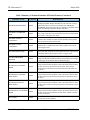
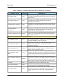
Table 1.Summary of Standard Database OIF Data Elements (Continued)
VARIABLE NAME
CHANGE
DESCRIPTION
Modified
This attribute of the Targetable Weapon permanent entity and for airto-air and surface-to-air weapons holds the index to the proper
damage array that should be used when assessing the damage caused
by weapon detonation. For air burst, surface burst, and sub-surface
burst weapons it holds the name of a SURFACE KILL LETHALITY
INDEX which points to the proper damage arrays AREA KILL
LETHALITY, PROB HIT LETHALITY and POINT KILL
LETHALITY.
Modified
This attribute of the Targetable Weapon permanent entity holds the
distance from the weapon impact point at which objects are subject
to the damage effects of the weapon after weapon impact, regardless
of which damage algorithm is used.
TW NUMBER MUNITIONS
Modified
This attribute of the Targetable Weapon permanent entity holds the
number of independent damage calculations that should be executed
when assessing the damage from a single Targetable Weapon of this
type.
TW PRECISION GUIDED
Modified
This attribute of the Targetable Weapon permanent entity is used to
indicate whether a weapon is precision-guided.
TW WC FACTOR
Modified
This variable attribute of the Targetable Weapon, Weather condition
compound entity holds the Targetable Weapon weather factors which
are the multipliers applied to the probabilities of hit when the weapon
is used during the specified weather condition.
TW DAY NIGHT FACTOR
Modified
This attribute of the Targetable Weapon permanent entity is a
multiplicative factor designed to adjust probabilities of hit when the
weapon is used during night conditions.
Modified
This attribute of the WEAPON DELIVERY CAPABILITY entity
holds the factor used to calculate the probability that the Weapon
Delivery Capability has no effect on the delivery capability of the
weapon.
TW LETHALITY INDEX
TW RADIUS OF EFFECTS
WDC DELIVERY FACTOR
JTLS-0245 Submarine Detection After Missile Firing
Added
This attribute represents the remaining detection time required to
localize a submarine after it fires a missile, if a passive sonar is within
range of the firing location.
IIP SUB FIRING
LOCALIZATION DIST
Added
This attribute represents the maximum distance allowed between a
detecting passive sonar and the firing location of a submarine
launched missile that results in a reduction in the amount of coverage
time needed to detect the firing submarine.
IIP SUB DETECTION TIME
REDUCTION
Added
This attribute holds the fraction by which a submarine’s remaining
required coverage time is reduced if a submarine launched cruise
missile is detected at the launch location.
IIP SUB FIRING
LOCALIZATION TIME
JTLS 3.3.0.0
1-15
Version Description Document
JTLS Document 17
March 2008
Table 1.Summary of Standard Database OIF Data Elements (Continued)
VARIABLE NAME
CHANGE
DESCRIPTION
IIP MAX RANGE FOR
REDUCTION
Added
This attribute represents the maximum distance between a detected
submarine-launched cruise missile and the submarine from which it
is launched, within which the detecting force can estimate the
approximate location of the submarine at the time of the launch.
TW DEPTH FIRING
CAPABILITY
Added
This attribute represents the depth areas from which this submarinelaunched weapon can be fired.
TW FIRING NOISE LEVEL
Added
This attribute represents amount of noise generated by the launching
mechanism of the missile.
TW FIRING NOISE TIME
Added
This attribute represents amount of time that the noise generated by
the launching mechanism of the missile affects the total noise made
by the submarine that fired the missile
JTLS-2005-1480 Lifeboat Representation
SUP LIFEBOAT HUP
Deleted
Multiple lifeboat types are possible for a single Ship Class.
SUP MEAN LIFEBOAT
DEPLOY TIME
Deleted
Individual lifeboat type deployment time are held in a new Small
Boat attribute, SB MEAN DEPLOY TIME.
SUP AVERAGE TIME TO
SINK
Modified
The average time required to sink a ship of this SUP type. Formerly
interpreted as the mean of an exponential distribution, this parameter
represents the mean of a normal distribution with standard deviation
equal to 0.25 of the specified mean.
SB AMPHIB CAPABLE
Added
Small Boats may be used during Amphibious Operations if this
attribute is set to YES. If it is set to NO, boats of this type cannot be
used for amphibious pickup or assault.
Added
When a ship is in the process of sinking, the Small Boat type (SB)
specified by this data parameter is used along with the HUP to create
lifeboats for the ship’s personnel, personnel from embarked
squadrons, and personnel from carried units.
SB MEAN DEPLOY TIME
Added
A random process determines the time interval between the
deployments of individual lifeboats using Small Boats of this type.
This deployment interval is selected from an exponential distribution
with a mean equal to the value of this data parameter
SUP SIMULTANEOUS
LIFEBOATS
Added
When a ship is in the process of sinking, this value determines the
number of lifeboat deployment efforts that can be in progress at any
specific time.
HUP LIFEBOAT TYPE
[JTLS-2005-1537 ELS Scenario Data Construction. These database parameters are added to the Combat System (CS)
table in the DDS and are used to automatically create ELS templates.]
CARRY_FLAG
Added
This Boolean value indicates whether this CS type can carry other
CSs while moving.
LIFT_FLAG
Added
This Boolean value indicates whether this CS type must be carried
while moving.
Version Description Document
1-16
JTLS 3.3.0.0
March 2008
JTLS Document 17
Table 1.Summary of Standard Database OIF Data Elements (Continued)
VARIABLE NAME
CHANGE
DESCRIPTION
PROTECTED_FLAG
Added
This Boolean value indicates whether this CS type is intended to be
placed in protected positions.
PUBLISH_FLAG
Added
This enumerated value indicates the circumstances under which
entities of this CS type are published by the ELS: ALWAYS,
NEVER, DISMOUNTED, and DISMOUNTED.COLUMN
JTLS-2006-1646 Provide TADIL-J Data
UT LINK-16 BLOCK START
Deleted
A Squadron is allowed to have a set of individual blocks of Link-16
Track Numbers to allocate to individual Aircraft in the missions that
it launches. These are defined by the MISSION Link-16 BLOCK
structure. Defining a single start and stop value for the Squadron is
no longer appropriate.
UT LINK-16 BLOCK END
Deleted
Removed for the same reason.
AC USMTF NAME
Deleted
Replaced by the AC REAL WORLD DATA OBJECT attribute. The
new attribute points to a new REAL WORLD DATA (RWD) entity.
Each RWD has four attributes, one of which is the RWD USMTF
NAME. The Aircraft obtains any defined USMTF Name from the
referenced RWD data parameter.
AC LINK16 CAPABLE
Added
This flag specifies whether an Aircraft of this type is capable of
providing Link-16 updates on air detections it performs.
UT JU NUMBER
Added
This text representation of an Octal Integer is converted to an integer
when read by the CEP. It is the unit reference for Link-16 Air Track
data reporting when air contacts are detected by an Air Search Radar
operated by the unit.
TG LINK16 BLOCK START
Added
This is the first Track Name in a block of Link-16 Track Names
allocated to an Air Search Radar Target
TG LINK16 BLOCK END
Added
This is the final Track Name in a block of Link-16 Track Names
allocated to an Air Search Radar Target
MLB OCTAL TEXT
Added
This text representation of an Octal Integer is converted to an integer
when read by the CEP. It is the unit reference for Link-16 Air Track
data reporting when air contacts are detected by an Air Mission that
is Link-16 capable and has received a block of Track Numbers from
its parent Squadron.
MLB START TRACK
Added
This is the first Track Name in one of the blocks of Link-16 Track
Names available for allocation by a Squadron to each Aircraft in its
air search Air Missions.
MLB END TRACK
Added
This is the last Track Name in one of the blocks of Link-16 Track
Names available for allocation by a Squadron to each Aircraft in its
air search Air Missions.
TW TADIL ID
Added
This is the unique name of the Targetable Weapon that is used by
certain U.S. and Allied C4I systems.
JTLS 3.3.0.0
1-17
Version Description Document
JTLS Document 17
March 2008
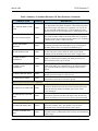
Table 1.Summary of Standard Database OIF Data Elements (Continued)
VARIABLE NAME
CHANGE
DESCRIPTION
AC REAL WORLD DATA
OBJECT
Added
This name references one of the REAL WORLD DATA (RWD)
entity objects defined in the database.
RWD NAME
Added
This is the name of one of the REAL WORLD DATA (RWD) objects
defined in the database.
RWD USMTF NAME
Added
This is the United States Message Text Format (USMTF) text name
of the AIRCRAFT CLASS entity that references this RWD.
RWD TADIL ID
Added
This is the TADIL-J/Link-16 text name of the AIRCRAFT CLASS
entity that references this RWD.
RWD TADIL MODEL
Added
This is the TADIL-J/Link-16 text Model Number of the AIRCRAFT
CLASS entity that references this RWD.
JTLS-2006-1654 Model Anti-Radiation Missiles
TW GUIDANCE TYPE
Added
This attribute of the Targetable Weapon permanent entity represents
the type of guidance used by the weapon.
ACP POST ATTACK SEARCH
TIME
Added
This attribute of the AIR CONTROL PROTOTYPE entity represents
the duration of time a fire control sensor will remain active after it is
automatically Turned On as a result of a close weapon impact.
Added
This attribute of the AIR CONTROL PROTOTYPE entity represents
the duration of time a fire control sensor will remain active after no
Cruise Missiles or non-friendly detected Air Missions are present in
its coverage area
Added
This attribute of the AIR CONTROL PROTOTYPE entity represents
the average duration of time a fire control sensor achieves the
TURNED ON state after it is automatically Turned On by the
occurrence of events in the game, instead of being ordered to become
active.
SLP EMISSION TEST
DURATION
Added
This attribute of the SUSTAINMENT LOGISTICS PROTOTYPE
entity represents the mean duration of time a SENSOR SITE target
will turn on to confirm proper operation after completing repair or
movement
ST SUPPRESSION TIME
Added
This attribute of the SENSOR TYPE entity is the average duration of
time a SENSOR SITE target of this type will shut down if fired upon
by a weapon with a TW GUIDANCE TYPE of ARM.
JT SUPPRESSION TIME
Added
This attribute of the JAMMER TYPE entity represents the average
duration of time a JAMMER target of this type will shut down if fired
upon at by a weapon with a TW GUIDANCE TYPE of ARM.
ACP POST DETECT SEARCH
TIME
ACP FIRE CONTROL
RESPONSE TIME
JTLS-2006-1658 Model Tactical TLAM
TW PROB BDA
Deleted
Version Description Document
Replaced by TW SENSOR TYPE, which holds the name of a valid
Sensor Type.
1-18
JTLS 3.3.0.0
March 2008
JTLS Document 17
Table 1.Summary of Standard Database OIF Data Elements (Continued)
VARIABLE NAME
CHANGE
DESCRIPTION
TW SENSOR TYPE
Added
This attribute of the Targetable Weapon permanent entity holds the
ST NAME of the SENSOR TYPE that this weapon uses to perform
BDA or RECCE.
TW SUBMUNITION TW
Added
This attribute of the Targetable Weapon permanent entity holds the
TW NAME of the Targetable Weapon that represents the
submunition for this weapon.
TW PROB LOSE GUIDANCE
Added
This attribute of the Targetable Weapon permanent entity holds the
probability per 100 km traveled that this weapon will lose guidance
control.
TW MAX SPREAD
ALTITUDE
Added
This attribute of the Targetable Weapon permanent entity holds the
maximum altitude that this weapon will use when determining
weapon spread for damage calculations.
TW ADV CAPABILITY FLAG Modified
This variable attribute of the Targetable Weapon permanent entity
holds a series of text flags that indicate the advanced capabilities of
this Targetable Weapon.
JTLS-2007-2177 Expand Command Level Representation
UT COMMAND LEVEL
Deleted
This unit parameter was formerly specified for land-based units only
and excluding Naval units. Command Level is instead assigned to
units, ships and HRus by their unit prototypes.
TW LETHALITY INDEX
Deleted
This element is replaced by new TW AIR AIR LETHALITY, TW
SURFACE AIR LETHALITY, and TW SURFACE KILL
LETHALITY parameters.
HUP COMMAND LEVEL
Modified
This database parameter was formerly a Foreign Key to the hardcoded Command Level lookup table. The Foreign Key currently
points to a new Command_Level table.
Modified
The mean time required to assemble a single railcar if the type
specified by the Supply Movement Asset (SMA) by the Faction that
owns this SMA on the rail network specified for this SMA. Formerly
an array, this single data value is Faction-specific.
SMA ASSEMBLY TIME STD
DEV
Modified
The standard deviation of the time required to assemble a single
railcar if the type specified by the Supply Movement Asset (SMA) by
the faction that owns this SMA on the rail network specified for this
SMA. Formerly an array, this single data value is Faction-specific.
CL NAME
Added
This attribute names a unit’s Command Level entity.
CL OTH GOLD NAME
Added
This name of the Command Level or Command Echelon is required
by Over The Horizon - Gold (OTH-GOLD) messages.
Added
The Command Level that a detached unit, created by detaching a
percentage of a parent unit or detaching a specific list of Combat
Systems and Supplies from a parent unit, should automatically
assume.
SMA ASSEMBLY TIME
MEAN
CL LOWER LEVEL
JTLS 3.3.0.0
1-19
Version Description Document
JTLS Document 17
March 2008
Table 1.Summary of Standard Database OIF Data Elements (Continued)
VARIABLE NAME
CHANGE
DESCRIPTION
CL ICON ECHELON
Added
This Command Echelon parameter defines the echelon symbols to be
placed in the icon as displayed on the Web Hosted Interface
Program Map Component.
TUP COMMAND LEVEL
Added
A unit using this TUP will assume this name of the Command Level
upon initialization
SUP COMMAND LEVEL
Added
A unit using this SUP will assume this name of the Command Level
upon initialization.
AB FIRING OBJECT
Added
This attribute names the owner of the Combat System that fired the
weapon.
AB FIRING SYSTEM
Added
This attribute references the Combat System that fired the weapon.
TW TYPE IMPACT
Modified
This attribute of the Targetable Weapon permanent entity holds the
identifier of the primary warfare area for which this weapon is used.
TW AIR AIR LETHALITY
Added
This attribute of the Targetable Weapon permanent entity holds the
identifier of the lethality data set that should be used if the weapon is
fired as part of an Air-to-Air engagement.
TW SURFACE AIR
LETHALITY
Added
This attribute of the Targetable Weapon permanent entity holds the
identifier of the lethality data set that should be used if the weapon is
fired by an Air Defense (SAM/AAA) site.
Added
This attribute of the Targetable Weapon permanent entity holds the
identifier of the lethality data set that should be used if the weapon is
fired by a Surface-to-Surface Missile (SSM) site, dropped on a
surface object by an Air Mission or fired at a surface by a High
Resolution Unit (HRU).
Added
This attribute of the Targetable Weapon permanent entity holds the
number of rounds or bullets to be represented by a single weapon of
this Targetable Weapon type. This parameter is not used by JTLS and
is of interest only for databases to be used for interaction with other
external models.
TW SURFACE KILL
LETHALITY
TW NUMBER ROUNDS
1.5.4 Standard Database Changes
The new JTLS 3.3 Standard Database based on Operation Iraqui Freedom (sdboif33) includes
extensive data item modifications implemented since the Standard Database (SDB) version 3.1
(sdbv31) release. If you have used sdbv31 as a basis for your existing scenarios, evaluating the
modifications included in sdboif is advised. A total of 99 Combat Systems, which are described in
APPENDIX B. of this document, are represented in sdboif. Reviewing your existing SDB-derived
databases and upgrading them to the new data standard is strongly recommended. The detailed
procedures required to upgrade sdbv30 or sdbv31 to sdboif are provided in APPENDIX C.
Version Description Document
1-20
JTLS 3.3.0.0
March 2008
JTLS Document 17
JTLS 3.3 includes significant functional changes that affect data. Significant adjustments to your
database are required to allow this model version to function properly. The Modify program that is
applied when DDS is executed will coorectly structure your database structurally to be compatible
with JTLS 3.3, but acceptable results will not be obtained from the model without changing your data.
The algorithms for calculating damage against surface and subsurface objects have changed. Naval
mine warfare has been completely modified with significant data requirements. New sets of Ship Unit
Prototypes using the 99 Combat Systems and multiple TW SSMs have been added for the first five
countries. Additional country sets will continue to be added and be available with the 3.3 interim
releases.
Sdboif33 contains significant changes that include:
•
New and revised Targetable Weapons (1082 total)
•
Specific torpedo weapons
•
New and more specific anti-ship missiles
•
New and more specific anti-tank missiles
New anti-radiation missiles
•
New artillery weapons
•
New naval gun weapons (burst and single round)
•
New surface-launched rockets and missiles
•
New air-launched rockets
•
New aerial gun bursts
•
New cluster munitions
•
New air-launched non-anti-ship bombs and missiles
•
New water mines
•
New Probability of Hit data and Probability of Kill data for all weapons used against all
appropiate Target categories
•
New Area Lethality sets that are based on the previous Area Lethality data sets
•
New Supply Categories (249 total)
•
New Combat Arms and Supply Type Target Subcategories
•
New Unit Of Measure (UOM) data for new Targetable Weapons
•
New Calibers
•
New Combat System Can Fire data
•
New Target Subcategories
JTLS 3.3.0.0
1-21
Version Description Document
JTLS Document 17
March 2008
•
New and modified existing Target Type Groups (TTGs)
•
New multi-use aerial guns and rockets (Air-to-Air and Air-to-Surface)
•
Weapon load and load assignment changes for new weapons
•
SSM and SSM-TW changes
•
All of new data required to support the water mine capability
•
NEW_NAVY_CSP replaced NAVY_CSP
•
All previous Ship Unit Prototypes (SUP) are removed
•
New SUPs for United States, United Kingdom, Australia, Iran-Iraq, and Russia
•
New Lifeboat data with new SUPs
Additional data items to support other planned 3.3 Naval improvements (Submarines) have been
postponed to an Interim release.
New data items were added to support the TADIL-J link to real-world Command and Control
systems, but are typically not used within the model. Data items were also added to enhance the
connection to JCATS through the Joint Multi-Resolution Model (JMRM). A separate section exists in
the DDS for JMRM related data. Most of these data items do not affect JTLS as executed in a
standalone mode.
Data development that remains to be accomplished includes:
•
As new data is used and results are observed, adjustments and corrections will be required.
Minimal testing has been accomplished to confirm the correctness of these new data.
•
Completely new Area Lethality data sets
•
New TW RADIUS OF EFFECTS based on new Area Lethality data
•
New Area Lethality terrain modifiers by Combat System
•
Lethality for runway-specific weapons, such as BAP100-9, JP233, BLU107.DURANDAL
•
New lethalities for HRU weapons
•
A complete revision of aircraft weapon loads and weapon load assignments, beginning with
the most commonly used aircraft
•
New TW weather modifier data
1.6 NSTALLATION NOTES
1.6.1 Installation Instructions
The JTLS Installation Manual (included in the documents compressed tar file that is part of this JTLS
release) provides detailed instructions for installing a new version of JTLS.
Version Description Document
1-22
JTLS 3.3.0.0
March 2008
JTLS Document 17
1.6.2 Oracle Compatibility and Installation
This release of JTLS requires a complete installation of Oracle Forms/Reports Developer 6i client/
server runtime.
Developer 6i is the final version of the client/server development and deployment of Oracle Forms,
Reports, and Graphics. Oracle Corporation will provide only limited support for this Developer
version until January 2008, and Oracle10g will become the final certified database server compatible
with Developer 6i. Beginning with the release of JTLS 3.1.0.0, Oracle 10g iAS EE (Internet
Application Server Enterprise Edition) has been implemented to deploy JTLS database applications,
such as DDS Forms. The compatible database server version is Oracle 10gR2 Standard Edition One
or newer. Database server requirements that are updated prior to a future JTLS release will be
described in the appropriate JTLS Version Description Document.
Utilizing the framework of iAS EE, which includes Forms Services, Reports Services, Portal, Single
Sign-On, Java, and other components, will enable the delivery of JTLS-specific data from a central
location. This also allows the development of more scalable JTLS database applications, such as the
SDR and AAR.
Currently, the following combinations of Forms 6i runtime and the Oracle Server are approved for use
with JTLS:
a. Oracle Database Server 9.2.0.8 or later (10gR2 Standard Edition One is recommended)
b. Forms 6i client/server runtime (with patchset 18 or later) for Solaris and/or Linux
c. iAS EE 10.1.2.0.2 full stack (optional)
Refer to Chapter 6 of the JTLS Installation Manual for additional details regarding the Oracle Forms/
Reports Developer 6i client/server custom runtime installation.
JTLS 3.3.0.0
1-23
Version Description Document
JTLS Document 17
Version Description Document
March 2008
1-24
JTLS 3.3.0.0
March 2008
JTLS Document 17
2.0 ENHANCEMENT CHANGE PROPOSALS
INTRODUCTION
JTLS 3.3.0.0 is a Major JTLS release that includes the implemented Enhancement Change Proposals
(ECPs) summarized in this chapter.
2.1 JTLS-0030 Friendly Naval Gunfire Support
2.1.1 Summary of Model Change Request
Previous versions of this design addressed the limitation that Direct Support could be provided for a
Supported Unit only if the user was allowed appropriate Command Authority. This problem was
corrected, but the design was subsequently expanded to include the capability to provide Direct
Support to units belonging to other Force Sides. This ECP properly implements the capability to
provide Direct Support to any Friendly side land-based unit (ARU only) in the game.
2.1.2 Design Summary
This design modifies several basic aspects of the combat model logic, including:
•
changing the acceptance criteria for the Direct Support (DS) Order,
•
accounting for any Force Side Relationship (FSR) change that affects either unit in an
existing DS relationship,
•
accounting for a ROE change for either unit,
•
accounting for any Side change by either unit, and
•
ensuring that AAR records are correctly provided and maintained.
Providing the DS if and when the Supported Unit enters Lanchester Combat was not modified as part
of this ECP.
The requirement that the Firing Unit must be either a Land Combat unit or a Naval unit, over which
the ordering Player has command authority, was not changed. Most other characteristics of the order
were unchanged. Examples include the ability to schedule the DS relationship in the future, the ability
to cancel future scheduled DS relationships, and others.
The Supported Unit can now be either a same side unit or a unit on any Force Side that the Firing Side
considers to be Friendly. The restriction that Naval Units and HRUs cannot be the Supported Unit
remains in place. These two types of units do not participate in Lanchester Combat as do the other
types of units. Additionally, since different Sides are now allowed, ROEs must be considered. An
JTLS 3.3.0.0
2-1
Version Description Document
JTLS Document 17
March 2008
ENEMY ROE behaves as expected, and prevents any DS relationship from being ordered, or from
continuing if the ROE is changed after the order has been accepted.
Another unchanged restriction requires that a unit can provide Direct Support to only one Supported
Unit at a time. However, a Supported Unit can benefit from the Direct Support of more than one
Firing Unit. If a current supporting relationship is identified when the order is received, but must be
canceled, the Player still receives a message describing the situation.
At the time that an ordered DS relationship is to begin (not the order receipt time), the model
conducts a series of checks to assess the order’s validity. These include:
• The Firing Unit’s Side must have a Friendly relationship to the Supported Unit’s Side.
• Neither unit can have a Ground ROE of Combat Approved against the other unit’s
Side.
• The Firing Unit cannot be supported by another unit.
• The Supported Unit cannot be supporting another unit.
Note that the Supported Unit’s FSR is not checked, according to the concept that the ordering side
knows its own FSR regarding the supported side, but does not know the actual FSR held by another
side regarding the ordering Side. This is not true for the ROE.
The JTLS ROE order allows a wide range of flexibility. For, example, a single Side A unit can have
Weapons Free ROE against Side B while Side A has a Friendly FSR to Side B. This allows
representation of ’rogue’ units and of other special tactical circumstances. Therefore, if a unit
currently in Direct Support of a foreign unit has its Ground ROE changed to Combat Approved, the
DS relationship will be terminated, regardless of the current FSR. The Air-to-Air and Surface-to-Air
ROEs will not considered, since Direct Support is exclusively a ground operation.
Correspondingly, if a unit on Side B that supported by a unit on Side A has its Ground ROE changed
to Combat Approved against Side A, the Side A unit will cancel its Direct Support. The Supporting
Unit is assumed to have knowledge of such a serious action. This theater-level modeling assumption
considers a situation that rarely occurs.
For both inappropriate ROE situations, the DS relationship will be terminated whether or not combat
actually occurs. None of the scheduled future DS relationship startups will be canceled due to ROE
changes. ROE will be verified at the time the relationship is scheduled to begin. The ROEs may
change several times before the Supported Units enters any Lanchester combat.
If a unit providing Direct Support changes Sides, its DS is canceled, whether the Supported Unit is on
the same Side as the defecting unit, or is on a Friendly Side. To establish a Direct Support
relationship, the ordering Player must have Command Authority over the Firing Unit. When that unit
changes Sides, this authority no longer resides with the original ordering Player and must be reestablished by another Player who has received Command Authority over the unit.
Version Description Document
2-2
JTLS 3.3.0.0
March 2008
JTLS Document 17
If a Supported Unit changes Sides, no action immediately occurs. The Firing Side may not know that
the Side change has occurred. If assistance to the Supported Unit is needed because it is in combat,
the model will verify whether the current FSR allows the support.
Finally, AAR Record keeping will record initial DS orders, and also any changes to DS relationships
or to scheduled DS relationships due to FSR or ROE changes. The complete design for this ECP lists
all individual AAR items that are recorded and the circumstances under which each is recorded.
2.2 JTLS-0064 Knots As Naval Default Speed UOM
2.2.1 Summary of Model Change Request
Current JTLS versions use Kilometers Per Day as the default Unit of Measure (UOM) for Naval
Speed in the Naval Move order and all orders that include this field. This design establishes Knots as
the Naval Speed default UOM.
2.2.2 Design Summary
Modifying the default UOM specification for the speed field in the XML file that defines the structure
of the Naval Move order template is not sufficient for a robust implementation of this design. A
complete solution involves allowing greater flexibility for developers to specify Units of Measure
(UOMs) for order fields of all types. These modifications will be consistent with the conversion
requirements to support the CEP and other processes.
2.3 JTLS-0126 Naval Mine Warfare
2.3.1 Summary of Model Change Request
The intent of this ECP is to represent the capabilities of Naval Mines in greater detail, including
modeling the laying, detecting, and clearing of mines in a more realistic manner. Specific issues to be
addressed included making the time to lay and clear minefields dependent upon the minefield type
and representing minefields deployed at different water depths.
JTLS represents both Land and Water Minefields. These are modeled as Targets that are created in
various ways (2 Controller orders, 6 Players orders, and database entries) and interact with objects in
the game (Ships, Land units, convoys, etc.). While the ECP specifically addressed Naval Mine
Warfare, it was logical that the enhancements for Naval mines and minefields be applied to Land
objects in order to achieve a consistent minefield representation.
JTLS 3.3.0.0
2-3
Version Description Document
JTLS Document 17
March 2008
2.3.2 Design Summary
To fully understand everything that was done under this complex ECP, refer to the Design Description
Document. It required a large number of database changes. Almost 40 new data items were added,
and 5 obsolete ones were deleted. The database changes affected 8 individual data structures:
Minefield Type (MFT), Target (TG), Targetable Weapon (TW), Ship Unit Prototype (SUP), Mobility
Counter-Mobility Prototype (MCP), Intelligence Info Prototype (IIP), Small Boat (SB), and Aircraft
Class (AC). Also, 3 completely new data structures were added: Mine Search Capability (MSC),
Mine Clear Capability (MCC), and Ship Speed Level (SSL). Finally, a new Air Mission Type, for
which Aircraft Loads must be defined, was added. Mine Laying missions are now distinguished from
Mine Clearing missions instead of both mission types being described as simply Mining Missions.
When a Minefield Target is created, it inherits most of the data defining it its database Minefield Type
(MFT). The MFT data structure now allows the database builder to describe minefields in more detail
and in a more realistic manner than was possible before the change. For example, a minefields is no
longer simply a Land or Water minefield. It can now be an Anti-Invasion minefield, designed to
hinder Amphibious Operations by attriting the invading forces, including their Small Boats.
Minefields Types (MFTs) now have a depth restriction attribute: Surface, Bottom, or Variable.
Surface minefields are always at zero depth. Variable depth minefields deployed at a Player-ordered
depth between the MFT Minimum and Maximum depth values. Finally, Bottom minefields can be
laid from the bottom up to the MFT maximum cable length of the minefield type. The depth zone
(DZ) within which a minefield exists affects the emplacement time, the probability of detecting each
mine in it, the time it takes to clear it and finally the probability that a mine a ship encounters will be
triggered (actually detonate). As a consequence of the addition of depth, it is now possible to have
two minefields of the same type in the same hex, providing the two are deployed at different depths.
How minefields are detected, reported, updated, and swept have changed. A minefield is no longer
either detected or not detected. Now, a Side’s perception of a minefield includes how many mines
have been detected, and how many mines in which Lanes of the minefield have been detected. The
concept of a Minefield Target having Lanes that can be all or partially cleared, and can be used by
ships traversing the minefield is implemented as part of this ECP. Every MFT has a defined Lane
Width, and has six lanes, equating to the six Hex Side directions. Minesweepers can still be ordered to
clear an entire hex of foreign mines. But now they can also be ordered to clear a path through a known
minefield in the hex. Ships that have knowledge of the minefield and its lanes can then use cleared
Lanes to traverse the minefield, and therefore have less chance of encountering a mine.
Minefields can be detected in various ways by various assets. Each asset that can detect a minefield or
can update knowledge of individual mines in a known minefield now accesses one of the new Mine
Search Capability (MSC) data structures. Each MSC has a list of individual mine probabilities of
detection by Minefield Type and Depth Zone. Visual detection of Surface mines depends on the IIP
Visual MSC accessed by the search platform. Similarly, Air Mission detection depends on the MSC
used by the Aircraft Class. And finally Ships use the MSC accessed by their Ship Class (the SUP).
Version Description Document
2-4
JTLS 3.3.0.0
March 2008
JTLS Document 17
Analogous to the Mine Search Capability data is the Mine Clear Capability (MCC) data. For a Ship
Class or Aircraft Class to be able to clear mines, it must access an MCC. Then, the MCC MFT DZ
MINE CLEAR RATE specifies the number of mines per day (of the MFT and in the DZ) the ship or
air mission can clear. Other new Aircraft Class (AC) data specify how big an area a mission can
search when it is on an Exploration (look for new minefields) mission, and how large an area it can
search when told to Recon (detect and report new mines in) known foreign Minefield Targets.
Another new data structure is the Ship Speed Level (SSL). Each Ship Class (the SUP) and Small Boat
type (the SB data) points to an SSL in the database. The SSL data specifies how the speed of the ship
or boat affects its ability to detect mines, the chance that it will encounter mines in a minefield it is
transiting through, and finally the probability that a mine it does encounter will actually be triggered
and damage the ship. In another part of the database, default mining operation speeds are held. The
Mobility Counter-Mobility Prototype (MCP) data now has the default speeds for ships that are:
Laying minefields, Exploring for new minefields, Recon of existing minefields, and Clearing mines.
These defaults can, of course, be over-ridden by Player orders. A ship that triggers a mine in a
previously unknown field will report the field, and then slow to its MCP-specified mine recon speed.
When a ship goes through the hex containing a minefield, it may "encounter" one or more of the
mines in the minefield. Different algorithms are used depending upon whether or not the ship know
about the minefields, and whether it knows about any cleared (completely or partially) lanes through
the it. For example, a ship would encounter more mines when transiting North-South through an
unknown field than it would if the field were know, and the North-South lanes were cleared. Finally, if
a ship does encounter a mine, and the mine does detonate, then damage is assessed against the ship.
This is done differently in this JTLS release, but the change is not covered by this ECP. Refer to ECP
JTLS-0239, Multiple Targetable Weapon Hull Hits for descriptions of how that is now done.
2.4 JTLS-0132 Perceived Naval Course and Speed
2.4.1 Summary of Model Change Request
JTLS object attributes are displayed on Player WHIPs only as they are perceived by a particular Force
Side and therefore may not reflect ground truth. For Naval units, such as ships and submarines,
perceivable attributes are initially limited to location, strength, posture, and specific information
pertaining to on-board targets, on-board squadrons, or lifted units.
For previous JTLS versions, Course, Speed, and Depth for detected Naval units were not perceivable
by a foreign Force Side and, consequently, were not displayed. The detecting Side should be
realistically capable of ascertaining these attributes after a suitable time has elapsed. This model
enhancement expands the perceived attribute list for Naval units to include Course, Speed, and Depth,
displays these vector attributes on the WHIP, and forwards them to C4I systems linked to JTLS.
JTLS 3.3.0.0
2-5
Version Description Document
JTLS Document 17
March 2008
2.4.2 Design Summary
Two new Intelligence Information Prototype (IIP) data parameters, IIP SURFACE VECTOR TIME
and IIP SUBSURFACE VECTOR TIME, were established within the model to define when an
observing object perceives Course, Speed, and Depth of a detected surface or subsurface Naval unit.
Two vector times were required to represent the inherent differences in tracking surface and
subsurface vessels. The existing Update Data entity, the data structure that holds perceived object
attributes to be reported, was modified to include the Course, Speed, and Depth attributes. The CEP
was modified to use the surface or subsurface IIP parameter as a mean of an exponential draw to
determine when an Update Information event should be scheduled to report the vector attributes from
the Update Data entity to the detecting Side. Refer to the JTLS Analyst’s Guide, Section 9.4.2, for a
detailed description of this process.
A new Depth field was added to the SITREP window displayed on the WHIP. The existing Course
and Speed fields were previously not filled for foreign Side Naval units. A Current Depth column was
added to the Naval Unit IMT. The CEP was modified to pass all three perceived vector attributes to
the JODA for the SITREP, IMT, and to display a Course and Speed vector attached to the detected
Naval unit’s map icon. The vector attributes currently appear on the WHIP SITREP and map at a time
after the Naval unit is detected or re-detected, based on the IIP vector times. Note that actual ground
truth vector data are used for own-side Naval units.
To support this enhancement, all directional attributes passed to the JODA, such as course, heading,
direction, and orientation, were reviewed across object types (Airbases, Ground units, Squadrons,
Naval units, etc.) for consistency. The JODA and CEP were modified as appropriate to eliminate
redundancy and confusion. Refer to Table 7 of the JTLS 3.3.0.0 design document JTLS-0132
Perceived Naval Course and Speed for a list of the revised direction attributes used by JODA objects.
2.5 JTLS-0239 Multiple Targetable Weapon Hull Hits
2.5.1 Summary of Model Change Request
This ECP provides significant enhancements to representing the damage caused by JTLS Targetable
Weapons (TWs). The original specific situation addressed involved one TW hitting a ship to cause at
most either one Hull Hit (for an Area TW), or at most one hit per TW NUMBER MUNITIONS (for a
Point TW). This methodology created several issues, including:
•
Inconsistent damage for a TW between Land and Sea victim objects. Multiple
submunitions designed to cause multiple hull hits made some TWs unrealistically
effective against land targets.
•
Damage was not always accurately represented because each submunition was assessed
separately. The Probability of Kill (PK) for a submunition is a combined Probability of Hit
(PH) and PK value. The difference between modeling individual PH-PK assessments and
Version Description Document
2-6
JTLS 3.3.0.0
March 2008
JTLS Document 17
determining one PH followed by multiple PK assessments for weapon hits needed to be
reevaluated. This is particularly important for representing powerful weapons, for which a
hit, even with a low PH, would cause most submunitions to inflict damage.
•
Area weapons did not use TW NUMBER MUNITIONS and could cause only one hull hit,
regardless of warhead size and type. If these weapons were not precision-guided, all the
weapons deployed in one pass could cause only one hull hit.
A new methodology, including numerous database structure changes, was required to allow the
database developer to indicate the level-of-damage potential of a weapon used against a ship without
causing negative affects on other aspects of the model. The multiple hull hit situation and the overall
TW surface and subsurface damage algorithm was considered. Changes to Air-Air and Surface-Air
TW algorithms were not included.
2.5.2 Design Summary
This major enhancement allows a TW to cause primary (Point effects) and secondary (Area effects)
damage, which required many database structure changes and significant algorithm modifications.
Refer to the corresponding JTLS design document for a complete description.
The SURFACE KILL LETHALITY (SKL) data structure provides the principal support for the
design concept that all weapons capable of causing damage use a Primary Damage algorithm to inflict
this damage. Additionally, a weapon that also has an assigned Area Kill Lethality data set also inflicts
collateral damage to all objects within the area of effects by means of a Secondary Blast Damage
algorithm. Targeting options include Land Units, Ships, Unowned Targets, Associated Targets, Land
Unit Owned Targets, HRU Owned Targets, Ship Owned Targets, DMPIs, and Locations. Damage
algorithms have unique characteristics for assessing each object type.
Each TW retains the characteristic of accessing a TW LETHALITY INDEX, which points to an AAL
or SAL for Air-Air and Surface-Air weapons respectively. With this enhancement, the index also
points to an SKL for sea/land weapons. The SKL subsequently specifies which PKL and possibly
AKL data the TW uses. Thus, the data parameter TW AREA OR POINT WPN is no longer needed
and has been removed.
All weapons that cause sea/land damage must have an SKL that has a specified PKL data set. Thus,
all damage-causing weapons will apply a Primary Damage algorithm. If the weapon also has
associated Area Kill data, a Secondary Blast Kill algorithm is also executed, which computes the
secondary effects of the weapon on other objects within the area of impact. Specifying an SKL set but
not an AKL set is allowed, but a specified AKL set without an SKL set is not allowed. Therefore, a
weapon cannot be defined as causing collateral damage only. However, defining an SKL that has
neither SKL nor AKL data, which causes no explicit damage on impact is possible. This SKL would
be used, for example, for Nuclear, Chemical, and Leaflet weapons.
JTLS 3.3.0.0
2-7
Version Description Document
JTLS Document 17
March 2008
Each SKL also points to another new data structure, the PROBABILITY HIT LETHALITY (PHL),
which holds PH data for victim Target Category and Subcategory combinations. Upon weapon
impact, a single random number is drawn to determine whether a hit occurs, using PH data. A hit or
miss also depends on whether the weapon is Precision Guided. Weather, Day/Night, and Weapon
Delivery Capability now modify the PH, not the PK. Hit probability also depends upon the weapon’s
TW SEARCH RADIUS. Only objects within this distance of the aim point are vulnerable. If a hit
occurs, each sub-munition is assessed separately, using the PK data.
After primary damage, if any, is processed and if the SKL has AKL, collateral damage is assessed.
The algorithm for assessing collateral damage acts differently depending on whether the TW hit or
missed. For a Hit, the impact point is the victim location; for a Miss, it is randomly determined within
TW SEARCH RADIUS of the ordered aim point. In either case, eligible objects within TW
EFFECTS RADIUS of the actual impact point are susceptible to collateral damage. Eligible objects
for collateral damage are Combat Systems that have a CSP CS EQUIVALENT TARGET
CATEGORY of Combat Arms or Supply Type, and Supplies that do not represent Combat Systems
and have an SLP SC EQUIVALENT TARGET CATEGORY set to Combat Arms or Supply Type.
The ship damage algorithms behave differently. For a targeted Ship, the model uses the PH value for
that unit’s Ship Unit Prototype (SUP) to determine whether the weapon hit or missed it. For a hit, the
model conducts TW MAX NUMBER HULL HITS random draws using the PK value for the SUP to
determine the number of hull hits and the level of damage the ship received.
Ships have watertight compartments. Objects on the ship (Combat Systems, supplies, targets, small
boats, catapults, assigned squadrons, and embarked units) are assigned to compartments. When a ship
receives a hull hit, a compartment is automatically damaged. Damage is assessed against all objects
determined to be in that compartment. Even if the PK for the SUP is zero, damage can occur to
shipboard objects such as owned targets and embarked assets, depending upon TW TYPE IMPACT.
Due to the complexity of this enhancement, reviewing the complete JTLS design document is
recommended.
2.6 JTLS-2005-1480 Lifeboat Representation
2.6.1 Summary of Model Change Request
High Resolution Units (HRUs) in JTLS have for quite a while had the capability to travel across water
terrain as well as land terrain hexes. They can be deployed from ships and recover to different ships
by using the Coalition Support order. Additionally, HRUs can be picked up from water hexes by
helicopters that have been assigned an Insert / Extract mission. Using HRUs to represent personnel to
be rescued when an air mission crashes was implemented a few years ago. The general data parameter
DOWNED AIRCREW HUP determines the type of the High Resolution Unit Prototype (HUP) that is
used to represent the downed aircrew. When an air mission is either shot down or crashes for some
Version Description Document
2-8
JTLS 3.3.0.0
March 2008
JTLS Document 17
other reason, the model randomly determines whether an aircrew HRU should be created. If the
random draw is favorable, the model automatically creates the HRU. If the aircraft crashed over water
and the assigned HUP has an organic small boat, the HUP is "magically" provided the small boat and
the HRU is placed in the water. Once created, the HRU is an independent JTLS object and can move
independently, be rescued by other ships, or be lifted to safety by Insert / Extract missions. It was a
logical follow-on to this concept to use the HUP/HRU structures to model lifeboat generation for
sinking ships.
JTLS-2005-1538 Improved Naval Damage was implemented for JTLS 3.1.0.0 provided the
foundation necessary to represent the deployment of lifeboats. As a result of JTLS-2005-1538, ships
in JTLS do not sink instantaneously. Rather, after suffering its last allowable hull breach a ship
assumes an INCAPABLE posture, it stops moving, and a sinking event is scheduled for a random,
database-dependent, time in the future. The purpose of this release’s ECP, JTLS-2005-1480, is to
deploy personnel, along with some supplies and combat systems, onto lifeboats while a ship is
sinking in a manner similar the model creates a downed aircrew. Other ships or aircraft can then be
ordered to move to the area and rescue these personnel. Although realistically personnel could be
"rescued" by enemy or suspect assets, this is not provided for within this design. That capability must
be postponed until a JTLS capture-and-surrender model is implemented. The same limitation exists
for the current representation of downed aircrews.
2.6.2 Design Summary
This change allows a sinking ship to attempt to deploy lifeboats holding some or all of the people on
board. These include ships company, personnel in embarked squadrons, and people in land units
embarked for amphibious operations. The time it takes a ship to sink is random, as is the time to begin
the abandon ship process and also the time for each lifeboat to be put in the water. The ship may have
one or several types of lifeboats aboard, each with its own capacity and average deployment time. The
ship’s crew may have the ability to deploy boats one at a time, or several simultaneously.
When a ship does not have any small boats assigned to it in the database, no HRUs representing
lifeboats can be created, and all hands are lost when it sinks. However, assigning small boats to the
ship class is not sufficient to allow survivors of a sinking. To be used as a lifeboat, a carried boat type
must be specified as the HUP LIFEBOAT TYPE for some HUP. The HUP structure now specifies
both which small boat type it uses if an HRU is dispatched by Player order on a tactical mission, and
also which small boat type is uses if it is to represent a lifeboat. Either or both of these can be NONE.
Also, a new SUP parameter specifies the number of simultaneous deployments of lifeboats that a ship
can conduct. If this parameter is set to zero, there will be no lifeboats, even if the ship has many small
boats on board. The larger the value, the faster boats are deployed. So, if lifeboats are possible for the
ship based on these criteria, then the model plays the role of the ship’s Captain and determines when
the abandon ship process should start. This decision may be a good or a bad one for the crew.
When the ship becomes INCAPABLE, the model randomly determines the actual sinking time based
on a random draw using the SUP AVERAGE TIME TO SINK. It then uses the number of people on
JTLS 3.3.0.0
2-9
Version Description Document
JTLS Document 17
March 2008
board, the number of lifeboats along with their capacities and load times, the number of simultaneous
launches allowed, and the value of the average time to sink for the ship class to compute when
abandon ship should start. The abandon ship time is computed so that if everything goes on schedule,
the last lifeboat leaves the ship just before it sinks. But since the time to start the abandon ship is
based on the database average time to sink, and the actual time to sink comes from a random draw,
some people may be left on board at sinking time and be lost, or alternatively all lifeboats may get
into the water long before the sinking. Of course if there are insufficient boats aboard, then some
people will always be lost when the ship sinks. Boats go into the water one at a time, represented by
HRUs of the type determined by the HUP associated with the small boat type.
The Player has the option to override the model-generated time for the abandon ship process to begin.
A new order, named ABANDON SHIP, allows the Player to specify exactly when the lifeboat
generation will start. This can be used to start the process immediately after the ship starts to sink, or
it can be used to delay the start of the process for as long as the Player desires. It can also be used after
the abandon ship process has started to delay or completely prevent additional lifeboat launches.
Lifeboats are deployed in the vicinity of the sinking ship. They are usually automatically moved with
the ship if the Controller Magic Move’s the ship. The exception is that if a Player is in the process of
rescuing them, they are not moved with the ship. Also, lifeboats automatically rejoin the ship if the
hull damage is magically repaired by a Controller before the actual sinking happens. If however the
ship stops sinking because a hull breach is automatically repaired by the model, the lifeboats stay in
the water. The idea is that the ship is assumed to be still in danger. Players can tell them to rejoin the
ship using the HRU REJOIN PARENT order, or leave them in the water until later.
Finally, lifeboats in the water of course stay in the game when the ship sinks. Their Parent Units
become the HHQ of the sunk ship, just as is the case with any HRU whose parent is destroyed. But if
the ship is resurrected with a REACTIVATE UNIT order, its lifeboats "jump" back on board. The
exception to this is that lifeboats that are in the process of being rescued (airlifted or sent HRU MOVE
orders, for example) do not jump back on board if the ship is reactivated.
2.7 JTLS-2005-1537 ELS Scenario Data Construction
2.7.1 Summary of Model Change Request
An extensive set of data files must be generated to utilize the JTLS Entity Level Simulation (ELS).
These files include a subset of the data held within the JTLS Combat Events Program (CEP) database
system, and a complete set of templates used exclusively by the ELS. The ELS requires these
templates to spatially lay out the command hierarchy and place the associated Combat Systems (CSs)
in geographic locations relative to their parent unit center. The ELS initiates the deaggregation of
theater-level units by breaking them down at the Unit Prototype level. For a typical JTLS scenario, the
number of Tactical Unit Prototypes, Ship Unit Prototypes, and High-resolution Unit Prototypes is too
large for a database builder to create a complete set of ELS templates in a reasonable amount of time.
Version Description Document
2-10
JTLS 3.3.0.0
March 2008
JTLS Document 17
An automated and straightforward method of creating and modifying templates must be developed to
support the simulation effort.
This design proposes a two-part method to construct the ELS-specific scenario data.
Part 1, Template Initialization, consists of a required subset of JTLS scenario data that will be
downloaded from the Oracle database, and a complete set of ELS Template files that may be created
using new options in the Scenario Verification and Initialization Program (SVP / SIP).
To construct Part 2,Template Customization, the ELS database builder may customize the Template
Files created in Part 1 by utilizing an editor accessed by means of a graphical user interface. This
graphical editor will provide the capability to manipulate the location, mounted status, and positional
priority for Combat System entities represented within ELS templates.
2.7.2 Design Summary
Implementation of this design is accomplished in several steps which involve changes to some
existing programs for Part 1, Template Initialization. A new component program must be created for
Part 2, Template Customization.
Template Initialization
For entity-level purposes, the ELS uses a subset of the data which are held by the Database
Development System (DDS) for the aggregate model. These data include the quantity and names of
the TUPs, SUPs, and HUPs, as well as the generic and CSP-specific names of all the Combat Systems
in the scenario. The DDS download of ELS data also contains Target information pertaining to the
number and types of Air Defense Targets, Aircraft Shelters, Surface-to-Surface Missiles, Runway
Targets (used for placing shelters), and Sensor Sites.
The ELS data subset is extracted from the DDS during the standard download from the system. They
may also be requested using an ELS-specific download from the DDS. An initial set of template files
may be created and verified for the ELS using portions of the Scenario Verification and Initialization
Program (SVP / SIP). During the creation process, the Combat System positions for the templates are
generated randomly to place all of the Combat System entities within the designated unit radius.
Every aggregate level Unit Prototype in the JTLS scenario will have a one-to-one relationship with a
single, top-level Template Object (TOB). The top-level TOB may be further deaggregated into
subordinate command levels, with at least one TOB at each level.
The separation of an aggregate Unit Prototype into its associated templates may be accomplished in
one of two ways. Database builders may directly specify a break-down of TUPs into subordinate unit
TUPs using the normal methods for creating and modifying TUPs in the DDS. Alternatively, the
templates may be automatically disaggregated into subordinates based on a specified number of
entities that are allowed for a given unit. Regardless of the method for disaggregation, template files
JTLS 3.3.0.0
2-11
Version Description Document
JTLS Document 17
March 2008
will be stored in a manner that allows several ELS database builders to independently manipulate
templates within a single scenario.
The consistency of templates and their associated database files may be verified using the SVP. For
automatically generated templates this is not a required step. However, when a database has been
changed such as changing the contents of a specific TUP, the associated templates may not be
consistent with the scenario data unless the templates are regenerated. The verification process checks
to see if all TUPs, SUPs, and HUPs have associated template files. It checks to see that the contents of
the templates are consistent with the scenario files in both the type and quantity of combat systems.
Template Customization
The ELS Template Builder (ETB) provides users the capability to edit the location offsets (relative
positions) of ELS template entities. This editor utilizes a graphical interface which allows the user to
visually select and modify the layout of entities with respect to their unit center. The editor interface
appears as three separate portions on the screen: a list of the template files with their breakdown into
subordinate templates, a list of the immediate subordinates (either templates or combat systems) for
the selected template, and a graphical layout editor for the selected template. In addition to the
template selection, the user may also modify templates based on the posture of the unit. Because the
ELS uses only four postures: Defend, Attack-Dismounted, Attack-Mounted, Move, the layout of
combat systems may be arranged in four uniquely different ways for each template. This editor also
allows the user to modify other attributes such as the mounting status of individual entities and the
priority of each position within a template.
2.8 JTLS-2006-1646 Provide TADIL-J Data
2.8.1 Summary of Model Change Request
This change includes model improvements that allow Link 16/TADIL-J data to be provided to
external programs via Network or Serial Feeds. The Maritime Working Group developed the original
design proposal in September 2005. However, the Link 11 data requirements currently defined were
transferred to a separate ECP.
The Global Command and Control System - Joint (GCCS-J) is designed to enable the command and
control of joint and coalition forces. Its Common Operational Picture (COP) correlates and fuses data
from multiple sensors and intelligence sources to provide warfighters the situational awareness
required for decisive action and response. This system is fielded at multiple sites worldwide, which
are networked within the Department of Defense classified private Intranet.
COP Master platforms on the GCCS-J and GCCS-M systems exchange track and other C2-related
data, such as Overlays and Position of Intended Movement Tracks (PIMTRACKS). This interface is
most often used within a Joint Task Force (JTF) environment in which the GCCS-M workstation is
Version Description Document
2-12
JTLS 3.3.0.0
March 2008
JTLS Document 17
used by the Maritime Component Commander (MCC) to exchange COP data with the Commander
JTF (CJTF) using a GCCS-J workstation.
Link-16 is a communications, navigation, and identification system intended to exchange surveillance
and C2 information among various C2 and weapons platforms. this system provides multiple access,
high capacity, jam-resistant, digital data, and secure voice Communication, Navigation, and
Identification (CNI) information to a variety of platforms. The Link-16/TADIL J segment allows
GCCS-J users access to this data and information.
Data are held within Link-16 messages. These are a series of predefined format (J series) messages
that can convey several types of data and voice transmissions. The messages are encrypted for
transmission and decrypted upon receipt. JTLS search, detection, classification, and tracking
algorithms accumulate data that can be utilized to develop Link-16 messages to update external
systems, such as GCCS, with simulated track data. This change adds that capability to JTLS.
2.8.2 Design Summary
Partial implementation of this ECP was delivered within JTLS Version 3.2. The ECP is complete with
this release. Foreign Air Tracks can be detected in JTLS and tracked by Air Missions carrying Air
Search Radars, and also by ground or ship-based Air Search Radar targets. When these tracks are
detected by Link-16 participants in JTLS, Link-16 track numbers are assigned, track data is
maintained and passed upward for use by external programs, and appropriate messages are generated.
Several JTLS data items must be set correctly to enable Units and Air Missions to be Link-16
participants. Aircraft types must be designated as Link-16 capable, Squadron Factions must have their
ACP AIR INFORMATION PROTOCOL set to "LINK-16", Squadrons must have blocks of Track
Numbers assigned for their detecting aircraft to use, Units operating air search radars must have a UT
JU NUMBER assigned, and the radar targets themselves must have blocks of track numbers.
The JTLS Operational Interface (JOI) is responsible for generating Link-16 messages in acceptable
formats for GCCS. With this release, JOI provides the following types of TADIL-J messages: Air
PPLI (Precise Participant Location and Identification, J2.2), Surface PPLI (J2.3), Air Track (J3.2),
Drop Track (J7.0), Air Platform Surface (J13.2), and Emergency Point (J3.1).
Real world Link-16 tracks that are detected by either an AWACS or an Air Search Radar Site are
assigned a Track Number from the detecting object’s available block of names. Track data are then
updated to a JTIDS Terminal located at the reporting unit. This unit may be a ship owning the radar,
the controlling unit for an Air Mission (its parent Squadron in JTLS) or a land unit owning a radar
site. The data are then passed to the TADIL-J segment of the COP to be made available to all
participants. In JTLS, the detecting object can be an AWACS Mission or a Target operated by a Unit
in the game. The reporting unit is either the launching Squadron for the mission or the operating unit
for the Air Search Radar target. JTLS track updates can be used to update the exercise COP while at
the same time real world tracks are being shown.
JTLS 3.3.0.0
2-13
Version Description Document
JTLS Document 17
March 2008
A JTLS Link-16 capable Squadron must have a set of blocks of track numbers (MLBs) to provide to
the mission aircraft. A detected aircraft is assigned a Track Name from the names between the start
and end of a Squadron block. Assigned Track Names are held by the CEP in a data set, which is
checked before assigning a new Track Name to ensure that the name is unique.
As the detected Air Track moves, its data are updated while remains detected. However, the track may
be covered by more than one sensor. Also, the track may extend beyond radar coverage, and return to
coverage range at a later time. The initially assigned name remains with the track until it escapes
coverage completely, even if tracking is passed to another Link-16 capable sensor.
Recall that a track is not lost immediately in JTLS when it extends beyond coverage. The data
parameter ACP DISTANCE TO LOSE AIR TRACK specifies the distance an air contact must travel
after escaping radar coverage before the track is actually dropped. If another Link-16 sensor assumes
the track before it has traveled this distance, then the Track Name remains the same, however, the
track data is revised to reflect the new object (Radar or AWACS) that is responsible for updates.
Regarding Prototype Owned Targets (POTs), the decision was to not include the option to assign
Link-16 Track Block Start and End values for POTs. However, the new MANAGE LINK-16
BLOCKS Order allows assignment, display, and/or changes to Track Block assignments and JU
NUMBERs for Squadrons, Units owning Targets, and for the Targets themselves. It can be used to
assign Link-16 participant data to targets created in the game from database POT definitions.
2.9 JTLS-2006-1889 Entity Viewer
2.9.1 Design Summary
This design describes a viewer for JTLS game entities. Originally named Java Virtual Battle Manager
(JVBM), this viewer is renamed Entity Viewer Interface (ENVI) and will fall under JTLS
configuration management. As such the ENVI will continue to be developed along with other JTLS
utilities. It leverages the same 3rd party graphic display libraries and receives its game data through a
connection to the EODA server. Additionally, this viewer is planned to incorporate an HLA interface,
Latitude/Longitude positioning of objects, a port to Linux and many other enhancements.
2.10 JTLS-2007-2001 Magically Expend Weapons
2.10.1 Summary of Model Change Request
A recent CEP enhancement allows a Controller to magically increase the weapons or fuel of an active
Air Mission. Specific weapons can be replenished, either individually or enmasse up to the original
weapon load. As a follow-on enhancement, JTLS users requested the capability to remove weapons
and/or fuel from an active Air Mission. Now, aircraft weapons and fuel can be magically expended as
well as replenished on a mission.
Version Description Document
2-14
JTLS 3.3.0.0
March 2008
JTLS Document 17
2.10.2 Design Summary
The existing Magic Air Ops order was modified to allow weapon and fuel expenditures. Four options
were added to the panel: Subtract Fuel, Deplete All Fuel, Subtract Weapons, and Expend All
Weapons. The Subtract options allow the player to specify the amount of fuel or quantity of each
weapon type to be removed (per aircraft) in the mission. The Deplete All and Expend All options
remove all fuel or weapons currently on-board every aircraft in the mission.
The underlying CEP software was modified to implement these options. After any weapons are
expended, the logic determines whether the mission should continue or not, based on the remaining
weapons needed to accomplish the mission type. For example, a CAP mission that no longer has any
air-to-air missiles will return home. If the fuel is reduced to near zero, the aircraft will crash (if fixed
wing) or land (if rotary wing). Magically expended weapons are not counted as "used" (i.e. not
considered dropped/fired). At the player’s option, the magically expended fuel or weapons can be restocked at the home base (or other specified unit) to keep logistics tracking in the model consistent.
2.11 JTLS-2007-2048 Transparency Slider
2.11.1 Summary of Model Change Request
To change the terrain transparency on the Map, the user must open the Preferences dialog, select the
Map node and then set the new transparency. It is desired to have this capability available on the Map
window.
2.11.2 Design Summary
Preferences are currently available in only one location, preferences manager. The intent of the
preferences manager is to provide a single consistent method for managing the preferences of the
various what components. Each preference category is presented as a single panel that can be
accessed by selecting the category in the preferences tree.
This design It is desirable to have preferences associated with a component accessible directly from
that component. This can be done by embedding the preference editor on the component.
JTLS 3.3.0.0
2-15
Version Description Document
JTLS Document 17
March 2008
A terrain transparency control was added to the button bar on the map component and was anchored
to the bottom. The slider is oriented vertically with a terrain icon and a label displaying the current
value above it. The user moves the slider and the terrain transparency is adjusted accordingly..
FIGURE 1. Terrain Transparency Slider
2.12 JTLS-2007-2050 Interactive Event Record and Replay
2.12.1 Summary of Model Change Request
Previous JTLS versions utilized the GENIS Data System (GDS) and the Graphical Interface
Aggregate Control (GIAC) Analyst Workstation (GAWS) to review portion of a previously executed
JTLS game. This capability was lost when JTLS evolved from this client-server system to the Web
Enabled JTLS Object Data Authority (JODA) platform. This design is intended to implement a
workstation recording and replay capability within this new system structure.
2.12.2 Design Summary
The event replay feature requires enhancements for most of the Web Services and the Web Hosted
Interface Program (WHIP).
A dedicated Logging JODA (Logging JODA) is the proposed process engine. This specialized JODA
saves information packets to various files as these packets arrive from the game’s Primary JODA.
Once the information is recorded, a JTLS user operating a specialized WHIP, named Total Recall
Interactive Playback Program (TRIPP) may recall a specified time period to replay the associated
Version Description Document
2-16
JTLS 3.3.0.0
March 2008
JTLS Document 17
recorded information. The requested replay period is not re-executed within the model, but the saved
data is instead resent to the TRIPP via the Replay Server, enabling users to review the recorded
situation. Figure 2 depicts this concept.
Primary
Logging
JODA
JODA
Data Save Files
Replay
Replay
XMS
JXSR
Replay Server
CEP
TRIPP
FIGURE 2. Replay System Concept
JTLS 3.3.0.0
2-17
Version Description Document
JTLS Document 17
March 2008
The TRIPP will appear much the same as a regular WHIP except that some functionality normally
provided to communicate with the model will not be presented to the user. This functionality includes
creating and sending orders, managing orders through the order group editor, and viewing messages
with the message browser.
2.13 JTLS-2007-2069 Java 6.0 Support
2.13.1 Summary of Model Change Request
The Java platform version used for JTLS development and execution must be upgraded from Java 5.0
to Java 6.0.
Version Description Document
2-18
JTLS 3.3.0.0
March 2008
JTLS Document 17
2.13.2 Design Summary
Version 6.0 of the Java Runtime Environment (JRE) platform was released in November 2006. This
release provides improvements that address several issues for the WHIP and GDP. Most notably, a
font management problem exists for the WHIP under Java 5.0 that is not present under Java 6.0. This
upgrade provides performance improvements and language features that will also be beneficial.
Java 6.0 will be delivered with JTLS 3.3 for Linux and Solaris.
Users will be required to install Java 6.0 in conjunction with the Microsoft Windows operating system
on client workstations to execute the JTLS 3.3 WHIP. JTLS 3.2 will continue to use Java 5.0 and
JTLS 3.3 will use Java 6.0. If both JTLS versions are used at an installation, each Windows
workstation will require both Java versions to be installed. Installing multiple versions of Java on a
single Windows machine is a common practice to support various Java programs that require different
runtime environments.
2.14 JTLS-2007-2086 JTLS Symbol Database Integration
2.14.1 Summary of Model Change Request
The old procedure used to add object symbols to a scenario database was error-prone and
cumbersome. Symbol loads to the database should be automatic and users’ actions should be limited
to creating a new symbol to be available to a database.
2.14.2 Design Summary
This enhancement was intended to solve problems that occurred when object symbols were created
and integrated to a JTLS database:
•
Saving the default symbols could overwrite one or more scenario symbols and the user
had to remember which scenarios were affected. If the user did not edit the default
symbols for a scenario, modifying symbols for multiple scenarios were difficult.
•
Applying symbols to the database was difficult. Previously, users could add, rename, or
delete symbols, which could create problems when symbols were loaded. A symbol that
was removed had to be set to NONE in the database.
These issues are addressed by implementing the concept of a symbol set that can be shared by several
scenarios and improving the symbol load scripts to automatically load when symbols have changed.
Additionally, restrictions are placed on symbol sets that are in use on the system. If a symbol set is
used by any scenario, symbols may not be deleted.
JTLS 3.3.0.0
2-19
Version Description Document
JTLS Document 17
March 2008
As part of the implementation, also the way the graphics symbol count read is modified. The symbol
count is no longer written in the record count ascii table, but directly read in from the graphics symbol
ASCII file.
2.15 JTLS-2007-2122 Change Combat System Maintenance Time
2.15.1 Summary of Model Change Request
A JTLS Controller can change the end-of-maintenance time for aircraft in a specific squadron using
the Change Maintenance Aircraft Time order. This order allows the Controller to increase or decrease
the duration of time one or more aircraft remain in maintenance at the squadron by specifying a new
end maintenance time. The specified time to end maintenance can be the current game time (i.e.,
ASAP) to force aircraft out of maintenance immediately. During exercises, a requirement may arise to
expedite other combat systems, as well as aircraft, through maintenance to meet mission tasking in
support of training objectives.
For previous JTLS versions, the ability to adjust maintenance times was available only for aircraft.
The Controller did not have the capability to change the repair times of other, non-aircraft Combat
Systems that were in maintenance. This enhancement has expanded the existing aircraft capability to
include all Combat System types within a unit.
2.15.2 Design Summary
The existing Change Maintenance Aircraft Time order was renamed as Change Maintenance Combat
System Time and modified to allow any combat system type to be selected for a specific unit.
Furthermore, two fields were added to the message generated by the Show Unit Combat Systems
order: Next Repair Time and Next Failure Time. The software was modified to permit the end
maintenance time to be changed for the selected Combat System type belonging to the selected unit.
Additional changes in the CEP were required to accommodate differences in the maintenance
processes between aircraft and non-aircraft combat systems. Previously, a Unit Repair event was
scheduled for each aircraft or group of aircraft that entered maintenance due to ground combat
damage or non-combat failure. An End Maintenance event was scheduled for aircraft that entered
post-flight maintenance only. The CEP was modified to allow aircraft to use the End Maintenance
event exclusively, regardless of the reason for entering maintenance. This change was necessary to
allow aircraft times to be adjusted independent of their maintenance source and to retain the existing
logic that reschedules the End Maintenance event when the Change Maintenance Combat System
Time order is sent.
Non-aircraft Combat Systems continue to use the Unit Repair event while only the next scheduled
repair time for a given Combat System type is retained for computational efficiency. (Note: Several
thousand Combat Systems are subject to maintenance in a typical JTLS scenario, and explicitly
tracking each system’s repair time is not feasible. Thus, only one Unit Repair event is scheduled for
Version Description Document
2-20
JTLS 3.3.0.0
March 2008
JTLS Document 17
each Combat System type per unit, regardless of the number in maintenance.) Unlike the aircraft End
Maintenance event, the Unit Repair event applies to a single Combat System entity (i.e. the next
individual tank scheduled to finish maintenance). Consequently, only one Combat System may be
adjusted at a time, while multiple aircraft may be adjusted simultaneously. New CEP logic was added
for non-aircraft Combat Systems to reschedule the Repair Unit event when the Change Maintenance
Combat System Time order is sent.
Further logic changes were required to ensure agreement between the Combat Systems IMT and the
Aircraft Availability IMT. The unit’s Combat Systems Array is adjusted for aircraft entering or
leaving maintenance, as well as other Combat Systems for any cause. The Multiple Maintenance Set
for aircraft is utilized for aircraft entering or leaving post-flight maintenance, in addition to other
maintenance causes, to ensure complete reporting to the JODA.
2.16 JTLS-2007-2177 Expand Command Level Representation
2.16.1 Summary of Model Change Request
JTLS previously represented 11 specific, Army-oriented, database independent, Command Levels;
"Squad" through "Army Group". When information is passed to real-world Command Control,
Communication, Computer Information (C4I) systems by the JTLS Operational Interface (JOI), a
Command Level must be assigned to each non-Naval unit. However, some of these units are not
Army units. This fixed set of Army-centric Command Levels did not satisfy C4I system requirements.
This JTLS Command Level representation needed to be expanded. In addition, the ECP also
requested that JTLS representations of the Army-centric "Branch" of a unit be reviewed and either
removed or revised since C4I systems do not use that data either.
2.16.2 Design Summary
First, the portion of the ECP referring to JTLS "Branch" data no longer applies. Branch data was
actually not a JTLS data parameter. The model used to determine the Branch based on the hard-coded
GENIS symbols that previously existed in JTLS. Since JTLS no longer uses these hard-coded
symbols, the data can no longer be linked to a unit’s symbol assignment. The symbol generated
Branch data parameter was previous used by the GENIS External Module (GEM) developed by the
Joint Warfighting Center (JWFC) to feed real-world C4I systems. The GEM used this information to
help determine the symbol required to display the aggregate unit on the Common Operational Picture
(COP). Neither the JOI nor any other programs within JTLS currently use Branch data, so this portion
of the ECP was not implemented.
As for Command Level, this data is now available for all Units and for HRUs. Each of these types of
units now has a UT COMMAND LEVEL (or HRU COMMAND LEVEL) attribute. The Unit or HRU
gets its command level from the TUP/SUP/HUP COMMAND LEVEL. However, the possible
Command Levels are no longer a fixed set of 11.
JTLS 3.3.0.0
2-21
Version Description Document
JTLS Document 17
March 2008
Command Levels are now database items. The data structure COMMAND LEVEL (CL) is new to
this release. As many as needed can be included in a specific scenario. Each CL has the following
four attributes.
• · CL NAME - A unique name for the CL, 15 characters maximum
• · CL OTH GOLD NAME - for use in OTH GOLD messages, 5 characters
• · CL LOWER LEVEL - Another CL, for use by some unit Detachments
• · CL ICON ECHELON - For use by the WHIP, fixed set of 11 "echelon" symbols
The TUP, SUP, and HUP database parameters are not required. In other words, they are specified as
"Null Allowed". If the prototype does not have a Command Level, the units initialized from the
prototype will not have a command level and the JOI will not send the Command Level to the C4I
systems that it feeds. The decision to allow no data was included since these data fields are not only
related to United States (US) C4I systems and should not be required for other than US scenarios.
A Detached Unit’s Command Level is determined by the circumstances of the detachment. A
previously attached unit gets its original command level back. And a "Detach by TUP" unit gets the
command level corresponding to the specified TUP. However if the detachment is by Percent or by
specified Combat System quantities, then the ordering player has an option. An optional field on the
order allows that Player to specify the command level of the new unit. If the field is left empty, the
new unit gets the command level specified for the parent unit’s CL LOWER LEVEL.
Note that there is NOT an attribute called CL HIGHER LEVEL indicating the next higher Command
Level. This was envisioned for use with the Attach Order, but the Government decided there should
not be any automatic Command Level changes as a result of the Attach order, so it was not added.
The CL ICON ECHELON now points to one of a fixed set of 11 symbols: X, XX, I, and so on. These
correspond to the old fixed set of 11 command levels. The CL ICON SYMBOL that a unit accesses
through its TUP COMMAND LEVEL is now only used by the WHIP display. The symbol that you
see on a WHIP map actually consists of two parts. The bottom part (the main symbol) comes from the
TUP GRAPHICS SYMBOL, while the top part comes from the TUP’s COMMAND LEVEL CL
ICON ECHELON.
Unit Size, which was defined for each unit in previous releases, is not related to either the
COMMAND LEVEL or to the CL ICON ECHELON. A unit’s size is based on the number of people
in the unit. Any number of UNIT SIZE (US) structures can be defined in a database. Each has a US
MINIMUM PERSONNEL attribute. As units gain or lose personnel, their UT SIZE can change, but
their ICON ECHELON will not change.
Finally, the manner in which the Assembly Times for Rail and Barge assets are defined has changed.
Recall that these assets are owned by Factions, not individual units. In previous versions, this data
was held in an SMA ASSEMBLY TIME MEAN (or STD DEV) ARRAY. The array held data for
Version Description Document
2-22
JTLS 3.3.0.0
March 2008
JTLS Document 17
each SMA (e.g., FLATCAR), for each of the 11 command levels. The command level of the shipping
unit dimensioned the array.
Since Command Levels are now database items, this methodology needed to be changed. Now, only
one value, the SMA ASSEMBLY TIME MEAN (or STD DEV) is held for each SUPPLY
MOVEMENT ASSET (SMA). Another SMA attribute is the SMA FACTION. So, the assembly time
for a barge or rail asset (an SMA) is now the same throughout a given Faction, and is independent of
any Command Level or Echelon data. In other words, within a given Faction a given type of Barge or
Railcar takes the same amount of time to be made available for its loading to start, regardless of the
command level or echelon of the unit requesting the assets.
2.17 JTLS-2007-2181 Properly Report JCATS-Owned Supplies
2.17.1 Summary of Model Change Request
In the JMRM federation, ownership of units may pass from JTLS to another model, i.e. JCATS.
Regardless of whether a unit is owned by JCATS the JTLS model continues to provide to its users the
usual set of status reports concerning all units in the game. Within these reports the JTLS user needs
some indication that the unit’s supplies are controlled externally.
2.17.2 Design Summary
This design implements criteria for supply reporting within JTLS that is sensitive to externally owned
units. For example, ownership of a JTLS unit may be passed to JCATS. The JCATS model then
controls nearly all aspects of the unit including supplies. The JCATS model is only concerned with
supplies of type ammunition and fuel. These three categories of supplies are therefore treated with
special consideration when the JTLS model issues reports on them for a unit owned by JCATS.
2.18 JTLS-2007-2188 Reflect External Air Weapon Expenditures
2.18.1 Summary of Model Change Request
This design provides an improvement to a CEP order and institutes HIP processing of an air mission
attribute, which may be updated by an external model. The condition for this is the JCATS Bridge
having ownership of an air mission and updating the count of weapons on the mission.
2.18.2 Design Summary
An air mission, as described in the JMRM FOM, has a Weapons_On_Hand attribute. The
Weapons_On_Hand attribute holds the counts of each weapon currently on the air mission.
Associated with another JTLS 3.3 design, JTLS-2007-2219 JMRM Rounds Conversion, the
JTLS 3.3.0.0
2-23
Version Description Document
JTLS Document 17
March 2008
JMRM FOM was modified to require the number of individual rounds rather than JTLS weapon
counts for this attribute.
Also, the External Update, CEP order was modified to allow weapon expenditures to pass from the
HIP to the CEP using whole JTLS weapon bursts. Again, by using design JTLS-2007-2219, the HIP
then applies one of a group of rounding functions to resolve the number of weapon bursts and then
updates the CEP by using the new External Update order. These enhancements allow the HIP to
statistically reflect expenditures for JCATS-owned air missions.
2.19 JTLS-2007-2189 SSL and Authentication for Apache
2.19.1 Summary of Model Change Request
Use of Secure Sockets Layer (SSL) and Authentication is needed for some JTLS exercises due to
network security requirements.
2.19.2 Design Summary
JTLS uses the Apache Web server to provide the WHIP access to the simulation data and scenario
files. Access to the Apache Web server must be unrestricted because exercises are typically conducted
on a closed (private) network.
This design presents an approach to implement Secure Socket Layer (SSL) communications for the
Apache Web server. Secure Sockets Layer (SSL) is a cryptographic protocol that provides secure
communications on the Internet for secure data transfers, such as Web browsing, e-mail, file transfers,
and e-commerce transactions. SSL provides the Apache server the capability to support Secure HTTP
connections that are similar to those used for online purchases or Internet banking. SSL configuration
is a simple system administrator activity. Apache SSL configuration for JTLS is more complex
because the Apache server is installed and executed from a user account. Configuration files are
required for each host computer that is configured to serve JTLS scenarios.
This design proposes the use of X.509 certificate keys. X.509 is an Internet standard for public key
cryptography and is supported by virtually all modern browsers, including Mozilla Firefox and
Microsoft Internet Explorer that are also supported by JTLS.
This design also includes an approach to implement server-side authentication for access to a JTLS
scenario Apache service. When an Apache server is configured for authentication, the server queries a
Web site user for a username and password, which are required for access to files on the Web site.
Version Description Document
2-24
JTLS 3.3.0.0
March 2008
JTLS Document 17
2.20 JTLS-2007-2218 Dual Air-to-Air and Air-to-Ground Weapons
2.20.1 Summary of Model Change Request
Some weapons, especially guns, have air-to-ground and air-to-air capabilities. These previously had
to be represented in JTLS as separate weapons, and Air Missions needed to have both weapons
loaded to properly represent their fighting capability. The problem was particularly troublesome when
JTLS participated in the Joint Multi-Resolution Model (JMRM) federation. This duplication had to
be corrected to properly represent guns within JTLS and to properly participate in a JMRM exercise.
2.20.2 Design Summary
In JTLS the 3.2 series, the database parameter TW TYPE IMPACT and TW LETHALITY INDEX
were two very closely related data elements. The TW TYPE IMPACT defined whether the weapon
was a sea/land attack weapon (AIR BURST, SURFACE BURST, SUBSURFACE BURST) an air-air
weapon (AIR TO AIR) or an air defense weapon (SURFACE TO AIR). This is still true. However, the
TW LETHALITY INDEX, which pointed to a single AKL, PKL, SAL, or AAL data set for the
weapon, was removed from the database. It was taken out as part of the JTLS-0239 Multiple
Targetable Weapon Hull Hits ECP, which is also delivered with this release.
The JTLS-0239 ECP provided for TWs to have both POINT (primary targeted object) and AREA
(collateral damage) effects. To do this, TW LETHALITY INDEX was replaced by the SURFACE
KILL LETHALITY (SKL) data structure. Each sea/land TW now accesses an SKL that can point
both to a PKL (Point damage) and also to an AKL (Area collateral damage) set of lethality data.
This JTLS-2007-2218 ECP is a logical and required extension of the JTLS-0239 ECP. Since the TW
LETHALITY INDEX no longer existed, there needed to be a way to access the lethality data for airair and surface-air weapons. This was done by adding two new Targetable Weapon (TW) attributes:
TW AIR AIR LETHALITY (pointing to an AAL data set) and TW SURFACE AIR LETHALITY
(pointing to an SAL data set).
Therefore, to implement this ECP it was necessary to allow a TW that should be both an air-to-air
weapon and also be capable of being used in a sea/land attack to have both a TW AIR AIR
LETHALITY and also a TW SURFACE KILL LETHALITY defined.
The change was not difficult to implement. SVP checks insure that Surface-to-Surface Missile (SSM)
sites, High Resolution Unit (HRU) Combat Systems, and Surface-to-Air Missile / Anti-Aircraft
Artillery (SAM/AAA) site each have weapons specified that have the required lethality data sets. For
weapons carried on air missions, no TW AIR AIR LETHALITY specified means the weapon cannot
be used to engage foreign aircraft, and no TW SURFACE KILL LETHALTY means the weapon
cannot be used to attack sea/land targets.
No changes were made under this ECP regarding how weapons behave during engagements (pE, pH,
pK, time between rounds, damage assessment, and so on). However the decision about when an Air
JTLS 3.3.0.0
2-25
Version Description Document
JTLS Document 17
March 2008
Mission should return home because of a lack of weapons had to be revised. The Return Home
decision criteria used by the model, playing the role of the crew, needed be expanded to account for
this change in weapon usage. The decision criteria is basically that if an Air Mission has no useful
weapons, it will automatically be sent home. But that criteria is applied differently to different
mission types. This is straightforward for some mission types, but a bit more complex for others.
•
CAP. These missions logically, need Air-Air weapons aboard to continue.
•
CAS and Armed Recce. These need air-ground weapons (TWs pointing to SKLs).
•
Air Attack, SEAD, Orbiting OAS, and Combat Approved ROE Patrol Missions. These
require weapons with a TW TYPE IMPACT set to AIR BURST, SURFACE BURST, or
SUBSURFACE BURST. This is true even if the mission still has on board primary AIR
AIR weapons that also access an SKL.
•
Air Refuel, EC, RECCE, Mine Warfare, and Weapons_Hold/No_Fire ROE Patrol
Missions. If these had Air-Air weapons in their original mission load, then they abort
when the weapons are gone. If they had none in their load, they do not abort for lack of
weapons.
•
Airlift, Transport, Transfer, AWACS, and Insert/Extract. These missions do not abort for
lack of weapons
Previously, users have also complained that some SSM sites also have an Air Defense capability. This
duality is not being represented as part of this design and is a separate ECP. However, a single
Targetable Weapon type can now be assigned to both a SAM/AAA site and an SSM site.
Any Targetable Weapons that can be fired from an SSM site, must have a TW IMPACT TYPE of AIR
BURST, SURFACE BURST or SUBSURFACE BURST. On the other hand, the only requirement for
weapons fired from a SAM/AAA site is that they point to an appropriate Surface Air Lethality data
set held by the Targetable Weapon attribute TW SURFACE AIR LETHALITY. Thus a single weapon
can be fired by an SSM site, a SAM/AAA site and even be placed on an Air Mission. Such a weapon
would for example have: its TW IMPACT TYPE set to SURFACE BURST, its TW SURFACE AIR
LETHALITY set to a valid SAL, its TW AIR AIR LETHALITY set to an AAL, and its TW
SURFACE KILL LETHALITY pointing to an appropriate SKL.
Finally, some new SVP errors have been created. The SVP now checks the TW IMPACT TYPE to
verify that air-air weapons access an AAL, surface-air weapons access an SAL, and that sea/land
weapons access an SKL. It also checks that weapons assigned to SSM targets have a sea/land impact
type, and that weapons fired by Air Defense targets access an SAL. Analogous checks are done by the
model before accepting Controller SET TARGETABLE WEAPON PARAMETER orders.
Version Description Document
2-26
JTLS 3.3.0.0
March 2008
JTLS Document 17
2.21 JTLS-2007-2219 JMRM Rounds Conversion
2.21.1 Summary of Model Change Request
JTLS and JCATS each use different internal representations for gathering and reporting rounds of the
same weapon. This is especially true during weapon fire interactions. This design addresses this
problem.
2.21.2 Design summary
The weapon data for JTLS required an additional parameter to store the rounds devisor. This devisor
is used by the HIP to convert rounds received from the JCATS Bridge into weapon bursts used by the
CEP. The JCATS Bridge is responsible for the same conversions on its end. The HIP then uses a set of
statistical rounding methods to apply the weapon updates to the CEP in the usual fashion. This
method gives a reasonable accounting of weapons between the two models.
2.22 JTLS-2007-2286 Provide JOI Time Late Object Counts
2.22.1 Summary of Model Change Request
JTLS provides an accurate COP representation through the JOI that is based on the last detection time
of tracks. However, as the game advances, the accuracy of some COP data deteriorates when based
solely on the last detection time. If an object has not been redetected for a while, the time stamp on
such object will get old and the object is considered "time-late". OPFOR ground tracks that were not
in contact with Coalition forces were most severely affected when they were not redetected.
This ECP provides a JTLS Operational Interface (JOI) capability to display the "time-late" track
counts on the JOI main window. Within the GCCS, COP operators can delete Time-Late tracks from
the COP according to their time-late criteria. Furthermore, future GCCS may include a capability for
automatic removal of the time late objects. Display of these "time-late" summary object counts are to
be used to align with the track summary displayed on the Common Operational Picture (COP).
2.22.2 Design Summary
JOI provides summary counts for total, active, and filtered-off objects, and these summary counts are
used by the JOI operators to compare them with the COP track summary. With this ECP, additional
summary counts to specify the time-late object counts are added. In JTLS (and JOI), these time-late
objects are still considered active and any updates will be sent to GCCS. When the object is
redetected, the time stamp for object is also updated. Display of an additional summary counts for the
"time-late" objects was requested so that the JOI operators can easily reconcile the differences when
the time-late objects are removed from the COP.
JTLS 3.3.0.0
2-27
Version Description Document
JTLS Document 17
March 2008
Four setup parameters are added; 3 time-late cutoff criteria for each different track type (AIR, GND,
and NAV), and time interval to indicate how often do we want to recalculate the time late object
counts. These parameters will be set by the JOI operator during the setup process and cannot be
changed once the JOI process is started.
At every update time interval, JOI will recalculate the difference between the current time and the
object’s last detection time for each object. If the difference is greater than the cutoff time, the object
is considered as "time-late" and the summary counts are adjusted.
The JOI main window is modified to display the time-late object counts for each object class, the
counts are updated every time the JOI recalculates the counts. These counts are used by the operators
to match with the summary shown on the COP.
2.23 JTLS-2007-2289 SDC Improvements
2.23.1 Summary of Model change Request
The SDC was designed as a Relational Database Management System (RDMS) alternative to
connecting as a JODA client. As such this SDR component was intended to provide all information
available via the JDS Protocol in the SDC database tables. Updating this information is currently
accomplished manually—the SDC code and the database table definitions are modified to reflect
changes to the JDSP. This inefficient and error-prone method causes significant maintenance
problems and increases SDC testing time.
Since the objects of the JDS Protocol are defined in an XML format, a code generator for the SDC
that utilizes the XML definitions would minimize these problems. Therefore, this model enhancement
creates an SDC code generator that produces the required source code as well as the database table
definitions. This guarantees that changes in the JDSP XML Definition file will be reflected in the
SDC and the database SQL file.
2.23.2 Design Summary
Since the SDC code and the database table definitions are now created directly from the JDSP XML
file a naming scheme for tables and columns was derived. This naming scheme prepends "SDC_" to a
JDSP object name to derive an SDC database table name. As an example, the JDSP object AIRBASE
has a corresponding SDC database table named SDC_AIRBASE. SDC column names generally
match the JDSP field names from which they are derived. The exceptions are compound fields, JEDIS
and array fields. The compound fields result in numerous SDC columns that are based on the field
name appended with an underscore followed by the field names of the compound object (for example
the Location type field destination produces the columns destination_lat and destination_lon). JEDIS
use a similar methodology to compound fields, except that any terminating "_id" is removed before
appending on "_index" and "_type" for the two resultant columns. Thus the JEDI field
lifting_formation_id results in two columns named lifting_formation_index and
Version Description Document
2-28
JTLS 3.3.0.0
March 2008
JTLS Document 17
lifting_formation_type. Lastly, array fields are represented as separate SDC tables where each entry
in the array corresponds to a row in the SDC table.
Time fields were formerly treated as a compound field with a text Date-Time-Group (DTG) portion
and the number of seconds since game start portion. This matched the JODA structure, but forced the
developer to translate the value into a different format if the DTG format was not desired. The
compound time fields have been compressed into a single SDC field that is now defined as a DATE
type field. This allows the developer to instruct Oracle to format the field into the desired output on
retrieval. These same changed were made for the OEC and AARC time fields. For applications that
insert time values into the OEC, and do not wish to modify their code the Oracle instruction "ALTER
SESSION SET NLS_DATE_FORMAT = ’DDHH24MI"Z"MONRR’;" will create a mask so Oracle
recognizes the old DTG format.
Due to this automatic code generation and naming scheme new tables have been added to the SDC (),
some existing tables have had their names changed (), and numerous tables have had column name
changes(). A complete list of the column name changes is available with the design document.
.
TABLE 2. New SDC Tables
TABLE NAME
TABLE NAME
TABLE NAME
sdc_ada_target_subtype
sdc_ada_target_subtype_azr
sdc_aircraft_class
sdc_aircraft_load
sdc_altitude_zone
sdc_command_authority_tag
sdc_dsa
sdc_dsa_v
sdc_force_side
sdc_highres_unit_prototype
sdc_player_mip
sdc_sensor_target_subtype
sdc_ship_unit_prototype
sdc_ssm_target_subtype
sdc_ssm_target_subtype_swa
sdc_system_event
sdc_tactical_unit_prototype
sdc_target_s
sdc_target_l
sdc_targetable_weapon
sdc_weather_front
.
TABLE 3. SDC Changes to Table Names
OLD TABLE NAME
JTLS 3.3.0.0
NEW TABLE NAME
sdc_ac_maint
sdc_aircraft_maintenance
sdc_arc
sdc_network_arc
sdc_base
sdc_airbase
sdc_cruise
sdc_cruise_missile
2-29
Version Description Document
JTLS Document 17
March 2008
TABLE 3. SDC Changes to Table Names
OLD TABLE NAME
NEW TABLE NAME
sdc_graphic
sdc_graphic_object
sdc_graphic_location_pts
sdc_graphic_object_v
sdc_model_status
sdc_simulation_state
sdc_node
sdc_network_node
sdc_supply_manifest
sdc_supply_manifest_item
sdc_ui_unit
sdc_unidentified_unit
sdc_ui_target
sdc_unidentified_target
sdc_weaponload
sdc_weapon_load
.
TABLE 4. SDC Tables with Column Name Changes
SDC TABLE NAME
SDC TABLE NAME
SDC TABLE NAME
sdc_aircraft_maintenance
sdc_airbase
sdc_airmission
sdc_backorder
sdc_cas_request
sdc_combat_manifest_item
sdc_combat_system
sdc_convoy
sdc_cruise_missile
sdc_damage
sdc_dmpi
sdc_dmpi_target_link
sdc_earthquake
sdc_faction
sdc_farp
sdc_fire_mission
sdc_formation
sdc_graphic_object
sdc_formation
sdc_graphic_object
sdc_ground
sdc_hru
sdc_iads
sdc_naval
sdc_network_arc
sdc_network_node
sdc_pending_order
sdc_pipeline
sdc_port_event
sdc_railroad
sdc_refuel_chit
sdc_roe
sdc_runway_cut
sdc_side_relation
sdc_simulation_state
sdc_squadron
sdc_strategic_manifest
sdc_strategic_plan
sdc_strategic_stop
sdc_supply_category
sdc_supply_manifest_item
sdc_support
sdc_target
sdc_unidentified_target
sdc_unidentified_unit
sdc_weapon_load
sdc_weather
Version Description Document
2-30
JTLS 3.3.0.0
March 2008
JTLS Document 17
To assist external developers to retrieve information from the SDC database, the C code structures
that the SDC uses fulfill this requirement are delivered with JTLS. This header file contains a separate
structure for each SDC database table with structure element names that match the database column
names. It is generated by the SDC stylesheet in conjunction with the JDS Protocol XML File and
therefore always reflects the current structure of the database. This file is delivered in the
$JTLSHOME/include/sdr directory.
JTLS 3.3.0.0
2-31
Version Description Document
JTLS Document 17
Version Description Document
March 2008
2-32
JTLS 3.3.0.0
March 2008
JTLS Document 17
3.0 SOFTWARE TROUBLE REPORTS
3.1 INTRODUCTION
This chapter describes the software error corrections implemented for this release.
3.2 ERRORS CORRECTED FOR THIS RELEASE
No Software Trouble Reports (STRs), which describe discovered and corrected code errors, have
been identified for this release. Code corrections completed for the previous JTLS 3.2 series of
releases have been tested with the model enhancements delivered with JTLS 3.3.0.0 and are included.
STRs that remain outstanding from previous JTLS versions are listed and described in Chapter 4 of
this document. Errors that are identified for JTLS 3.3.0.0 and corrected for future Maintenance
releases in the JTLS 3.3 series will be described in this chapter.
JTLS 3.3.0.0
3-1
Version Description Document
JTLS Document 17
Version Description Document
March 2008
3-2
JTLS 3.3.0.0
March 2008
JTLS Document 17
4.0 REMAINING ERRORS
4.1 INTRODUCTION
Every effort has been made to correct known errors in the model. All reproducible errors that resulted
in a CEP catastrophic software failure (Crash) have been corrected. Other corrections were prioritized
and completed according to their resource cost-to-benefit relationship.
Correction of the remaining STRs, however, must be postponed to a later version due to time and
resource constraints. These problems may be corrected prior to the next release of JTLS. If an
immediate need arises for a code correction to any of these outstanding STRs (i.e., for an exercise
planned to occur before the next release), contact the JTLS Configuration Management Agent. (Refer
to the Abstract of this document for the current address.)
4.2 REMAINING ERRORS
The errors described in this section should be noted specifically because they affect the basic
functionality of JTLS. Information is provided regarding the extent of the error, as well as suggestions
to avoid or minimize the effects of the problem.
4.2.1 JTLS-0639 Error Determining When Engineering Task Completed
When a Unit starts a directed Engineering Task, the time to complete the task is based on the Unit
being at 100%. The time to complete a task is adjusted for the Unit’s COMBINED
EFFECTIVENESS. Stronger units complete tasks faster than do weaker units. The task completion
event is then scheduled at the computed time. At this scheduled completion time, the code checks
whether enough time has actually elapsed to complete the task. If the Unit was at more than 100%
COMBINED EFFECTIVENESS when the task started (meaning the task completed earlier than if
the Unit were at 100%), it appears to the model that not enough time has passed and the task is not
credited as complete.
4.2.2 JTLS-0695 Shadow Distance Of Zero Overriding Protection Radius
In the routine SEND INTERCEPTOR, the model is determining which interceptor to send. If this is a
protection radius CAP mission, it gets the minimum of PROTECTION RADIUS and SHADOW
DISTANCE. If this is zero, then the logic says there is really an infinite protection radius. This seems
odd. If someone forgets to set SHADOW DISTANCE, then protection radius is ignored. As a
minimum, this needs to be either documented or changed so that a zero SHADOW DISTANCE
means ignore shadow, not make protection radius infinite.
4.2.3 JTLS-0696 Missions Ignoring Assigned Altitude on Egress
Why aren’t missions observing their assigned altitudes on a egress path? Somewhere the posture of
JTLS 3.3.0.0
4-1
Version Description Document
JTLS Document 17
March 2008
the mission was changed to HEADING HOME when it is on its egress route. This causes the mission
to automatically set its altitude to avoid air defense.
4.2.4 JTLS-0697 Missions On The Ground With Invalid Destination
Missions on strip alert report a next destination latitude/longitude on the IMT. The destination
coordinates should be cleared for missions on strip alert.
4.2.5 JTLS-0698 Cannot Re-Activate Destroyed Targets
Some facility targets are 0% capable and not displayed on the GIAC. They need to be reactivated for
the ATO. Activation cannot be done with Controller Change Target because their GDS active flag is
set to zero.
4.2.6 JTLS-0699 Targets That Require An Owner Are Disassociated
Targets owned by an HRU that die in combat are disassociated from the HRU and from their
associated unit. When a checkpoint is taken, both fields are written as NONE. On restart, this causes a
crash for ADA targets.
4.2.7 JTLS-0700 GIAC Not Displaying Current Runway Length
A runway has 21% strength, but the GIAC displays the maximum length and current length as equal
to the maximum length. In the GENIS, the percent capable is reduced, but the range and current
length values are the same. The model does not appear to update the current length to the GDS when
it changes.
4.2.8 JTLS-0701 Air Movement Report Does Not Consider Hold Points
When an air movement report is requested, it does not take into consideration scheduled delays in the
delivery instructions. As a result, it indicates an earlier departure time at each point, and an earlier
completion time for the mission.
4.2.9 JTLS-0702 Mission Waiting For Delayed Mission
An air mission package had an attack mission that went into weapons delay. The user told another
attack mission to join the package, but did not cancel the old mission. The new mission launched,
dropped its weapons, and then turned into an Escort and waited for the old Attack mission that was
still in Weapons Delay. The logic needs to be improved.
4.2.10 JTLS-0703 Periodic Report Other Side Airbases Lists No Activity
The Periodic Report Other Side Airbase Summary lists all the airbases but for each one says there are
no squadrons operating there. On the GIAC, you can click on the enemy airbase and see squadrons
there. Click on the squadron and it says that the home base is the expected home base. Discrepancy is
Version Description Document
4-2
JTLS 3.3.0.0
March 2008
JTLS Document 17
that the periodic report in BUILD FOREIGN BASE SQUADRON REPORT looks for squadrons at
the airbase, and perceived combat system aircraft for that squadron. If no aircraft have been
perceived, then it does not count as an operational squadron. There is no check whether the squadrons
are actually perceived to be associated with the airbase; truth is used instead. This provides free
intelligence. The discrepancy is that GIAC reports the home base but it does not show on the periodic
report.
4.2.11 JTLS-0704 Immediate Cancel Of Air Mission in Delay Status
During a recent exercise, the air cell sent an Air Transport Order in which the aircraft was directed to
remain on the ground at its home base until a certain time. This was a error, and the controller
cancelled the mission. The mission did not cancel immediately, but waited until the “holding posture”
time was complete and then cancelled. The Controllers stated that the mission should have cancelled
immediately.
4.2.12 JTLS-0705 Missions Launching With Fewer Aircraft Than Available
A mission that cannot get its resources goes into the UT AWAITING LAUNCH SET CAN YOU
LAUNCH looks only at missions in this set. If CAN YOU LAUNCH assigns enough aircraft to meet
the acceptable launch fraction, the mission is removed from the UT AWAITING LAUNCH SET and
a launch event is scheduled. Thus, once a mission gets the aircraft to launch, it will not fill up to its
full complement even if aircraft become available.
4.2.13 JTLS-0843 Error 427
When a ship and formation was in a dual capable hex, this error message appeared in the verify:
“Error 427: Formation, <name>, has been placed at hex location ###,###. This location is not
specified as water.” No error was recorded for the ship, which was located in a dual capable hex. An
error message should not be generated if the ship and formation are in a water, dual capable, or small
island hex.
4.2.14 JTLS-0846 Naval Unit Distance Calculation
A Player ordered naval Unit A to arrive at a point due west 100 nautical miles away at a time 12 hours
later with a speed of 10 knots. Naval Unit B was ordered at the same speed and direction to a arrive
24 hours later at a destination 200 nautical miles away. Unit A arrived 1.5 hours late and Unit B
arrived 3.0 hours late. The orders were repeated for both units to arrive at points 100 and 200 nautical
miles due north. The units arrived within 15 minutes of their expected arrival time. Although a speed
of 10 knots was ordered, the speed displayed for each unit in the SITREP window was 9.7 knots. The
model appears to not calculate the additional distance required when a unit follows an irregular path
from hex center to center. The problem does not appear when a unit follows a direct path from hex
JTLS 3.3.0.0
4-3
Version Description Document
JTLS Document 17
March 2008
center to center in any direction.
4.2.15 JTLS-0865 Incorrect External Program Order
If a non-GIAC program sends an incorrect order to the CEP, the CEP attempts to detect the error and
generate a Player message reporting it. The model crashed generating this message while executing
an order generated by the JTLS HLA Interface Program (JHIP).
The CEP code was modified to be stable under this specific circumstance. This does not guarantee
that another erroneous order sent to the model will not cause a different problem in another portion of
the code. Processing an order through the Order Verification Tool before submitting it to the model is
the only procedure which assures that such errors and crashes will not occur.
The JHIP condition which initially caused the problem was not a code error, but a mismatch between
the JHIP version in use and the version of the External Update order used by the CEP. The order
version was updated to match the JHIP version. This problem is not considered an STR because it
was discovered in a delivered non-official interim release of JTLS.
4.2.16 JTLS-0869 Continue Engage Determination
The A CONTINUE ENGAGE parameter is not used in JTLS 3.0. Due to the complete change of the
air-to-air algorithm in this version, the determination of when and how an air mission decides to
continue the engagement needed to be redone.This was not completed prior to the release of v3.0. It is
the desire and intent of the design team to restore this capability to the model.
4.2.17 JTLS-0870 Number of Air-to-Air Combat Kills Allowed
The code allows the weapons from a firing aircraft to kill only one enemy aircraft. A specific aircraft
should be able to target and kill multiple enemy aircraft up to its weapon control capability. This is
calculated as the number of weapons fired by the aircraft divided by the maximum number of
weapons allowed per enemy.
4.2.18 JTLS-0871 AC Mission Weapon Drop Determination
Currently, an air mission drops all of its air-to-ground weapons when an aircraft is killed in air-to-air
combat if the AC Weapon Drop Flag is YES. This flag value should also allow a mission to drops
non-precision guided weapons when it is fired upon in air-to-air combat.
4.2.19 JTLS-0906 Change ADA pE To Per-Element pE
An Air Defense Class has a Probability of Engagement (pE) against each of the Aircraft Target
Classes. If detection by a sensor on an IADS network is prompting the engagement, then the pE is
assumed to be 1. The following applies only to non-IADS detection and engagement attempts. Each
time an air mission enters a hex within the SAM-AAA target altitude-range criteria, the SAM-AAA
target attempts to detect the air mission with its fire control sensor. If the detection is successful then
Version Description Document
4-4
JTLS 3.3.0.0
March 2008
JTLS Document 17
the SAM-AAA target makes a pE attempt. It doesn’t matter how many elements are in the target, only
one detection attempt and one pE attempt are made per hex. But each element, by definition, has an
independent fire control ability.
Each fire control sensor in the multi-element target should conduct a detection attempt. For each
successful attempt, a separate pE attempt should be made. Assuming there is some form of command
and control within the elements of a specific SAM-AAA target, the actual firing can still be limited to
one element.
4.2.20 JTLS-0907 Scud-Like SSM Representation
It is difficult to represent the effects of long-range ballistic missiles. Different missile types have
various levels of accuracy in the CEP. However, in JTLS the missile will always hit its aimpoint. To
reflect the inaccuracy of these missiles, it is typical to assign them an unrealistically large TW Radius
of Effects. This usually results in very low damage effects from these weapons.
A new measure of the missile’s accuracy could be added to the CEP as a new database value, and used
to randomly determine the impact point of the weapon in a region surrounding the aimpoint. Thus, the
actual weapon impact effects could be properly represented within the model.
4.2.21 JTLS-0908 Naval IADS Link Representation
The IADS network for ship units is computed during the exercise as needed, based on the current
location of ships which have Comm Sites. In some cases this can be CPU-intensive. Currently, all
ship-owned Comm Sites can serve as hubs, i.e., these sites can send and receive all information. In
reality, only a few ships serve as hubs or air defense control centers for the Task Force. The other
ships’ Comm Sites are used only to pass detection information to the hubs, and receive detection
information and fire guidance.
A new Comm Site data parameter should be added to designate that a Comm Site subcategory is a
hub. A ship with a Comm Site target that is not hub-capable can link only to a ship with a Comm Site
target that is hub-capable. A ship with a hub-capable Comm Site target can link to any other ship with
any Comm Site target, within current side and distance restrictions.
4.2.22 JTLS-0909 Display Moderate And Severe Attrition Level
There is no capability to query whether a unit is suffering Moderate or Severe Attrition Level effects.
This capability should be added to the Unit Situation Report.
4.2.23 JTLS-0910 HRU Patrol Intel Reports
Typically, many HRUs are conducting intelligence gathering patrols simultaneously during an
exercise. Too frequently, they are collecting on “ANY UNIT”. These messages are all broadcast
messages, controlled by the Intelligence selection of the Broadcast Options menu. A workstation
operator has no capability to limit received intelligence reports to only those of interest. The HRU
JTLS 3.3.0.0
4-5
Version Description Document
JTLS Document 17
March 2008
Patrol Intelligence message should be modified from a Broadcast message to a Sending Workstation
message.
4.2.24 JTLS-0911 Fire Artillery Wait Time Between Missions
Artillery can be fired continuously within the simulation. Ammo constraints can be played through
supply category quantities, but frequently aren’t because logistics is not a training objective. Artillery
cannot realistically fire continuously without a cool-down period and maintenance time. The crew
also needs to eat and rest at some point. The overuse of artillery during exercises has been an issue for
several years.
Enforcing a minimum time between fire missions is a recommended capability. This could be
accomplished with a fixed database value, a database percent of the previous fire mission time, or a
FLP value. As a fixed value, 10 minutes would mean no new fire mission could start until at least 10
minutes after the completion of the previous fire mission. As a percentage, 25% would mean waiting
2.5 minutes if the previous fire mission time was 10 minutes, or waiting 15 minutes if the previous fire
mission time was one hour. Fire missions that are broken up because of the combat assess or the max
fire mission time should not be subject to the wait time between the split parts of the mission. Priority
Counter-battery missions should not be subject to the wait time because they are priority missions and
very time-dependent. Just as the number of hours a day that a unit can move is limited, a similar limit
could be put on the number of hours a day that a unit can fire.
4.2.25 JTLS-0929 Ship Changes Sides
A Thailand ship changed sides when a Mandatory Transfer order was given to a US ship. The ship
(FFG-456) was ordered to join an AOE-2.f formation. The Mandatory Transfer order to AOE-2 to
give FFG-456 50,000 gal of Cl.III Navy was rejected for the reason that FFG-456 appeared to have
changed sides.
4.2.26 JTLS-0934 HRU Overwatch
An HRU was created and assigned overwatch of a flying squadron. The model refused the overwatch
and reported “Unit is already in land combat, and not eligible for new overwatchers.” The flying
squadron had been attacked by terrorist HRU, which was no longer present in the area, as shown on
both U.S. and Controller views. Unit was at 84% strength. IMT showed flying squadron as being in
combat. When HRU broke off, flying unit should have come out of “In Combat” posture. The HRU
should have accepted overwatch responsibilities.
4.2.27 JTLS-0942 Air Transport Cannot Combine Wet And Dry Supplies
When both wet and dry supply categories are included in the same Transport Instructions List for an
Air Transport mission, they will not be transported at the same time. The first supply category
shipment type will be loaded, but the second will not. If both are included in the same Supply List, the
wet category is preferred. The aircraft go through the motions as if loading and delivering the denied
Version Description Document
4-6
JTLS 3.3.0.0
March 2008
JTLS Document 17
category, including MISREP confirmation. No pickup or delivery is made, although an empty storage
area may be created. There is no documentation to support this situation, and the user is not notified
of the problem.
4.2.28 JTLS-0948 Lanchester Double Kills
When two opposing units’ centers are within DECISIVELY ENGAGED DISTANCE of each other,
100% of the combat systems are eligible to kill each other. The combat power distribution of the units
is used to determine which combat systems are eligible to kill units in the same or adjacent hexes that
are not co-located. This can lead to some combat systems being allocated to kill twice in a single
Assess Combat period.
4.2.29 JTLS-0949 Destroyed Target SITREP Strength Incorrect
When a target is destroyed, such as a bridge or pumper station, the GIAC SITREP still has the
strength of the target as 100. GENIS also displays strength as 100. Apparently, the percent capable is
being updated in GENIS from JTLS, but not the strength which is used to fill the GIAC SITREP. This
is a problem in both 1.85B and the 2.0 versions
4.2.30 JTLS-0950 JTLS Radius Of Effects
The radius of effects for air missions is not being calculated correctly. The analyst guide states that
the radius of effects is determined by the TW.RADIUS.OF.EFFECTS of the area weapons employed
and the delivery altitude of the air mission. At the max altitude for the aircraft type, the covered area
is the total area for all area weapons fired. Testing has shown that the max radius of effects occurs
when the aircraft’s mission altitude is anywhere between one half the max aircraft altitude and max
aircraft altitude. In the routine, Determine Covered Radius, the area overlap calculation statement
shows the max altitude multiplied by 0.5. As such, the radius of effects is not calculated correctly.
4.2.31 JTLS-0952 Air Report
JTLS 1.85 provided the ability to obtain the report for one squadron or all squadrons. JTLS 2.0 only
provides capability to get one unit at a time.
4.2.32 JTLS-0953 All Sides Informed About Supply Dump Error
Created a supply dump using the Cache Order. Looking at the GDS shows that all sides are informed
about the dump; they show up on all sides IMT. Only the controller and the side that created the dump
should be initially informed about the dump.
4.2.33 JTLS-0954 Multiple Supply Storage Targets
A supply storage target should not be allowed to be created in the same hex as another one on the
JTLS 3.3.0.0
4-7
Version Description Document
JTLS Document 17
March 2008
same side. A user was able to create several open storage supply targets right on top of each other.
4.2.34 JTLS-0955 Air Lift Drop Report Message
The subject line of the message received when a player requests an air lift drop report for a mission
that has completed the lift or drop, or is not conducting a lift or drop, reads “Air Order Received,
<mission name>, Cannot Comply”. It should be titled, “Air Lift/Drop Report Cannot Comply”.
4.2.35 JTLS-0956 MPP Messages For Canceled Missions In Error
If an airbase is magic moved with several squadrons on active missions that need to be canceled or
with squadrons in the middle of a self lift, the subsequent message generated for the situation has
several errors. The changes required are too risky during the exercise. The problem will not cause a
crash, but will cause the MPP to incorrectly display the message contents.
4.2.36 JTLS-0957 Can’t Take Control Of Unowned Runways
It is impossible for anyone to take control of an unowned runway in the hex it is already in. To do this
the controller must enter the order, but the order is not on the controller’s menu. We have tested this
on a sample menu, it doesn’t crash but the runway’s owner is not set.
4.2.37 JTLS-0958 Withdrawing Units Cannot Destroy Supply Targets
There appears to be an error in the interface between the CEP routines DESTROY CACHES ON
LEAVING and IS TARGET SAFE. The first calls for supply targets that are another side or BLACK,
but the second always says BLACK targets are safe. This means that a unit withdrawing will never
destroy BLACK SUPPLY TARGETS, even if they could do so. The code needs to be updated, a
complicated fix.
4.2.38 JTLS-0959 Logistics Report Problem
The Logistics Report will report amounts as single decimal points (e.g., “.”). This is caused by format
D(8,0), and an amount smaller than 1 ton. To correct this situation, all of the Logrep files need to be
checked to determine if it is feasible to change the D(N,0) format specifications to at least D(N,1).
4.2.39 JTLS-0960 Can’t Magic Move Airbase To Existing Airbase Location
One cannot Magic Move an airbase into a hex wherein there is a runway that is on the same side as
the airbase, and is part of the initialization database. The airbase will not automatically assume
control of the runway. If the runway is one that was created by Controller action, the airbase will
assume control of it. If this error is causing problems for upcoming exercises, the Configuration
Version Description Document
4-8
JTLS 3.3.0.0
March 2008
JTLS Document 17
Manager should be contacted for a code fix to solve this problem
4.2.40 JTLS-0961 Group Ground Move Delayed To Lead Unit
There is a problem when a group ground move is sent. The directive is delayed to the lead unit. When
the lead unit learns about the move, it immediately tells the units in the follow-on group. This could
lead to directives being received out of order. Assume the user sends a directive at 0100 and the CEP
determines the lead unit should receive the message at 0200. The lead unit cannot receive any other
directives until after 0200. The CEP ensures that directive receipt is in the same order as the user sent
the directives. This is not true for the follow-on units. If the user sent an order at 0115 directly to one
of the follow-on units, the follow-on unit could receive the 0115 directive prior to the order sent at
0100. If this error is causing problems for upcoming exercises, the Configuration Manager should be
contacted for a code fix to solve this problem.
4.2.41 JTLS-0962 Pass Unit Intelligence Does Not Include Update Information
Pass Unit Intelligence does not follow any of the Update Information logic, so we are not going
through routines such as Alter Launch New Information procedure. This can cause Air Missions to
head toward old perceived information locations if they rely totally on the information obtained
through Pass Unit and Pass Target Intelligence capability. If your scenario involves a side which
depends solely on this intelligence collection methodology and the side will be sending attack
missions, the Configuration Management Agent should be contacted immediately to obtain a proper
fix to this problem prior to your exercise.
4.2.42 JTLS-0963 IMT Supply Category Line Disappears When Value Is Zero
Recommend that a Unit’s IMT On-Hand Supplies (OHS) specific category line remain when supplies
are gone and no Due-Ins are established.
When a unit runs out of a supply category and no Due-Ins are scheduled, the unit’s IMT On-Hand
supply line for that specific category disappears from the menu. This makes it very difficult for a
player who is controlling 40 or more unit icons and being overwhelmed at times with MPP messages
to keep track of exactly what supply categories need his attention or thwarts his attempts to troubleshoot a supply problem. The constant presence of the supply category line, even if empty, will save
the Player wasted time either making early printed copies of all his unit OHS for later comparison or
referring unnecessarily to the OPM TUP/SUP to determine what empty supply categories his units
have that require resupply. Certain supplies (i.e. fuel/targetable weapons) are critical and
unnecessarily impede game execution, if not maintained at required levels for play in an automated
logistics scenario.
4.2.43 JTLS-0964 Reporting Bridge Damage
When an aircraft conducts an air-to-ground mission against a highway bridge, damage reporting is
not consistent. When the aircraft returns and the mission report says the bridge is at 0% capability, the
JTLS 3.3.0.0
4-9
Version Description Document
JTLS Document 17
March 2008
IMT and SITREP still report the bridge capability as 100%. When another aircraft is sent against the
bridge, it flies over and doesn’t drop any munition because, according to the mission report, the target
isn’t there (it’s destroyed). When this aircraft returns, the IMT and SITREP still report the bridge at
100%. Much later, although not consistently, the bridge status changes in the IMT and SITREP to 0%.
If the bridge is destroyed, the IMT and SITREP should reflect the information provided in the
Mission Report. The problem reported is being investigated. If this is causing a problem for an
upcoming exercise, the Configuration Manager should be contacted to implement a fix to the problem
as soon as possible.
4.2.44 JTLS-0965 Error In Time Report For SET SP CONVOY DELAYS
When a time value of 2 hours 0 minutes is entered into any field of the SET SP CONVOY DELAYS
window and then sent to the CEP, the MPP returns a message that shows a time of 1 hour 0 minutes
instead. This is a known round-off error. A solution is being investigated.
4.2.45 JTLS-0966 Incorrect Mission Report Locations
Some mission report locations appear to be incorrect. The ADA engagement location is an example.
The problem is being investigated.
4.2.46 JTLS-0967 Fire Mission Not Deleted From GENIS
It appears that, in some circumstances, an Artillery Fire Mission that has been reported to the IMT is
deleted from the CEP without the GENIS being informed. This happened in the case of a unit that
was moving when it was supposed to fire the mission. The Fire Mission still showed on the IMT
several hours later.
4.2.47 JTLS-0968 Inconsistency Between Regular Run And Pusher
There is a major inconsistency between a regular run and a run created using pusher. When an order
with ASAP is sent, the READ KEYWORD routine sets the data parameter to TIME.V. When pusher
reads in the order, TIME.V is much earlier than it was when the order arrived in the first place. For
orbiting missions and alert missions, this alters when they will go off alert by a great deal. This must
be fixed and made consistent. It appears that both TIME.V and order receipt time must be saved to the
ci1 file to accomplish this task.
4.2.48 JTLS-0969 Changing Mission On Alert
When a ship moves, it changes the attributes of missions that are on alert. It also needs to change alert
hex for those missions that are not currently on alert, but still have their alert hex pointing to the ship’s
Version Description Document
4-10
JTLS 3.3.0.0
March 2008
JTLS Document 17
location.
4.2.49 JTLS-0970 Availability Of Aircraft
When a unit loses a fraction of an aircraft to Area Fire or Lanchester combat, the whole aircraft
becomes unavailable for air missions. However, the report of Available Aircraft on the IMT is
expressed in whole numbers. This may result in a unit incorrectly showing a damaged aircraft as
available.
4.2.50 JTLS-0971 Ship Continuous Tracking Not Working
The new unidentified object design indicates that ships which are continuously tracked will not have
unidentified objects created. A continuously tracked Naval unit and all of its targets are creating
unidentified objects. They should not be doing this.
4.2.51 JTLS-0972 Air Mission Find In Middle Of Ocean
A user does a find on a pre-launched air mission that is home based on a moving Naval unit. The X
marking the location of the pre-launch mission is where the Naval ship was when the order entered
the system. As the ship is moving, the new location of the pre-launch mission is not being sent to
GENIS and thus GIAC.
4.2.52 JTLS-0973 Periodic Report Air Supplies And Fuel Not Correct
The arrays which hold air supply usage are not being maintained correctly given the new MISSION
RESOURCE ALLOCATION event.
4.2.53 JTLS-0974 Submarine Detection By Ground Sensors
A moving submarine does not get full credit for coverage time by sonars on board other ships or
submarines. It gets full coverage time for airborne sensors but not ground based sensors.
4.2.54 JTLS-0975 GDS Target Update Error
When the CEP accomplishes a GDS Target Update, the GENIS ends up knowing about the reinitialized target, but the GIAC does not.
4.2.55 JTLS-0976 Manual Pairing And Protection Radius
The JTLS 2.1 Analyst’s Guide, Section 8.4.8.2, second paragraph discusses the rules for manual
pairing of CAP missions. The paragraph states that the manual pair order will only check to
determine if the new interceptor has enough fuel and appropriate weapons before sending it.
In the model however, a manual paired mission will do the following if the intercepted mission is out
of the protection radius of the interceptor. The interceptor will move one hex towards the intercepted
JTLS 3.3.0.0
4-11
Version Description Document
JTLS Document 17
March 2008
mission, and then return to its orbit location.
4.2.56 JTLS-0977 Slightly Inaccurate Runway Length Sometimes Used
When AIRCRAFT.CLASS data are read, the takeoff and landing lengths are read in integer format.
These are then assigned to the double real attributes of AIRCRAFT.CLASS. However, sometimes the
double attributes become values slightly larger than the actual version of the integer in the database.
4.2.57 JTLS-0978 Air Missions Don't Completely Comply With Egress
Each assigned point on an air route has an associated altitude. The mission should climb (or descend)
to that altitude upon reaching the point and attempt to maintain that altitude until another altitude is
assigned. Air missions that have egress routes should fly from the last egress route point to home base
at the altitude assigned for the last egress route point. They are not doing so. Instead, they fly from the
last egress route point home at their Most Efficient altitude.
4.2.58 JTLS-0979 Halted Helo Squadrons Show Mission As MOVING
A helicopter squadron can be ordered to conduct a ground move to a new location. A helicopter
squadron that is moving will accept orders to launch aircraft. However, when it begins air operations,
it stops. After the completion of air operations, the squadron does NOT resume its ordered movement.
Its posture reverts to DEFEND, but its “Mission” remains “MOVING”. Since the squadron does not
resume its move, its “Mission” should also revert to “DEFEND”.
4.2.59 JTLS-0980 SVP Warning 22
SVP Warning 22 reports aircraft loads whose extra fuel exceeds the aircraft’s wet carry capacity. I
believe the check should be changed to see if the extra fuel (carried in pods/tanks) when added to the
other weapons exceeds either the aircraft’s dry carry capacity or total dry/wet carry capacity. Granted,
there are other supply loads that might carry wet supplies, but in the case of extra fuel, I don’t believe
it should be considered wet weight.
4.2.60 JTLS-0981 Formation With No Posture
The model crashed when a formation reached a Destination Two hex and the formation no longer had
a posture. Therefore it did not know what to do. A Destination Two hex indicates that the Formation
should conduct its assigned Amphibious Operation, drop off its Sealifted supplies or clear mines from
a minefield. The posture of the formation is used to tell the formation which of these three tasks
should be accomplished.
When the formation reached its Destination Two hex, the posture of the formation was zero;
Version Description Document
4-12
JTLS 3.3.0.0
March 2008
JTLS Document 17
therefore, the formation did not know which of the three tasks should be accomplished.
4.2.61 JTLS-0982 GIAC Shows HRU Mission Moving After Move Complete
The GIAC Message Box Unit SITREP for an HRU continues to show a Mission of MOVING when
movement is complete. Unit Posture changes to DEFEND. ARU SITREPs are displayed with both a
Mission and Posture of DEFEND.
4.2.62 JTLS-0983 IMT/GIAC Show Insert/Extract Mission Flying
IMT and GIAC show Insert/Extract Mission flying at zero feet from Insert/Extract to next Transit
Point. Also between some Transit points. Radar detection reports correct altitude.
4.2.63 JTLS-0984 IMT Doesn’t Add Unit Names
IMT - Intelligence - Foreign Units will display the current list of identified Foreign Units and will
update information about them while the Foreign Unit Information window remains open. However,
if a new Foreign Unit is identified, that unit does not get added to the list in the open window. A new
Foreign Unit Information Window must be selected to obtain the current list of identified units.
4.2.64 JTLS-0985 PSYOP Results Multiplier
The PSYOP Results Multiplier was referred to as the PSYOP Effects Multiplier four times in the Data
Requirements Manual (DRM) and three times in the Analyst’s Guide. Although listed in the DRM,
the PSYOP Results Multiplier could not be accessed in the DDS. It appeared to default to 1.0 in the
game for all units. Controller - Set Individual Unit Parameters permitted entries from 0.00 to 1.00, but
all
entries
below
0.50
were
converted
to
0.50.
The
DRM
showed
a
UT.PSYOP.RESULTS.MULTIPLIER range from 0.001 to 999999.99.
4.2.65 JTLS-0987 Set Periodic Report Times
The Controller has the ability to change both the frequency of Periodic Reports and the number of
Periodic Reports between Summary Reports. However, there exists no ability to specify when the
next Periodic Report should be, or which of the next reports should be a Summary Report. As an
example, if the Controller wishes the blue side to receive Periodic Reports every 8 hours starting at
0600, and wants the Summary Report to be produced at 1400, then they must set the time between
periodic reports to 6 hours, and reset it to 8 hours after the 0600 report. Additionally, the number of
Periodic Reports between Summary Reports must be set to 2, and then reset to 3 after the 1400
JTLS 3.3.0.0
4-13
Version Description Document
JTLS Document 17
March 2008
reports. An easier method should exist to accomplish such a task.
4.2.66 JTLS-0988 Can’t Repair Naval Catapults
Naval Units cannot repair their catapults because they do not know they have a repair capability.
4.2.67 JTLS-0989 Controller Damaged Aircraft Not In Periodic Reports
When a Controller kills an Aircraft, the model does not tally, therefore the current periodic report
does not report the kill. The categories of kills do not logically cover the Controller killed aircraft.
The Post Processor Reports do include the Controller killed aircraft. This improvement can be made
in at least two ways. First the current Aircraft Kill Periodic and Summary Reports can be expanded to
include a category for Controller killed aircraft. A second solution is to remove the Periodic and
Summary Aircraft Kill Periodic and Summary reports, and get the data from the Post Processor.
4.2.68 JTLS-0993 Weapons Report on Mission Report
When a Player uses the Change Air Mission Parameter order to modify a mission’s weapon load prior
to takeoff and the order is implemented, the Mission Report does not always reflect the change. In at
least one case, when the final Mission Report was received, the only weapon listed was the new
weapon that was added. The report also incorrectly showed that zero of those weapons were returned
when none were actually fired. The mission fired several weapons from the original load, but none of
those weapons were listed in the final report, even though they were fired.
4.2.69 JTLS-0994 HRU Creation Target Requirements Assessed Incorrectly
If an HRU that is to be created and extract targets from its parent unit cannot find a target that is 100%
capable, it will refuse creation, even if the parent has a 12-element target that is 97% capable and the
HRU needs only one element.
4.2.70 JTLS-0999 Cancel Naval Mission Fails When A Unit Is Specified
The Cancel Naval Mission order allows either a unit or a formation to be entered. However, if
anything other than a formation is entered, the order is rejected on the grounds that the formation does
not exist.
4.2.71 JTLS-1010 Controller Cannot MM NEUTRAL Unit Onto Formation
The Controller cannot Magic Move a unit onto a Formation unless both FS FS RELATIONSHIPs are
Friendly. A player can pick up a unit via AMPHIBIOUS PICKUP as long as the relationships are no
worse than Neutral. The Controller should have the same capability. However, all implications must
Version Description Document
4-14
JTLS 3.3.0.0
March 2008
JTLS Document 17
be considered before implementing this solution.
4.2.72 JTLS-1017 Airlift Mission Problem
An airlift mission was created to pick up a NEO icon. The mission did not have the lift capacity to lift
the entire icon, so a second mission was created to pick up the same icon. The second mission went
into unit delay when it arrived at the pickup location. The first mission picked up then dropped off the
first load, then returned for the second load. The second mission should not have gone into unit delay
status.
4.2.73 JTLS-1260 EMCON Order Problem Subordinates of Embarked Units
If the primary Unit specified on an EMCON order is embarked on a ship, the CEP rejects the order,
even if the order is supposed to apply to subordinates as well. A possible solution is to take the UNIT
CHECKS off the order itself, and put them in the code that turns the emitter on and off. The only time
that the order should be denied is for a unit that has been wiped out, and it has no subordinates, and is
not in anyone’s UT SUBORD SET. If this is done a possible problem is having the IMT show the
sensor/jammer turned on while the unit is still not arrived, or is embarked on a formation. There
appears to be no problem inside the CEP, but the IMT bit is the reason that it has not been fixed. The
players have a work-around—Magic Move the unit ashore, send the order, and then MM back onto
the formation.
4.2.74 JTLS-1328 SAM/AAA Initial Issue
Currently, when a SAM/AAA target comes into the game, either at game start, TPFDD arrival after
game start, or target create; the owning unit or associated unit sends the initial issue of ammo to the
target site by an implicit resupply action. This implicit resupply convoy requires time to dispatch,
time to travel, and time to receive. In Standard Database this means it is 2.5 to 3.5 hours after a SAM/
AAA target arrives in the game before it has any ammo and is able to engage an air object; even if it’s
in the same hex as the owning unit. There is no reason for this restriction. A SAM/AAA target should
be given its initial issue of ammo instantaneously upon arrival in the game. The owning or associated
unit should still have its supply levels decremented based on the supplies that it passes to the SAM/
AAA target.
4.2.75 JTLS-1341 Assign Multi Attack Order
An OAS mission was assigned a set of targets using Assign Multi Attack order. After the order was
sent, that set of targets was deleted and a new set was assigned. The mission proceeded to the area
where the old targets were located, then headed toward the new targets. and not drop on either set of
targets. The mission should have headed toward new target area immediately after targets were
JTLS 3.3.0.0
4-15
Version Description Document
JTLS Document 17
March 2008
assigned.
4.2.76 JTLS-1351 Air Missions Refuel And Fly At Zero Altitude
When specifying ingress and egress routes for an air mission, it is possible to specify refuel points and
transit points. A transit point requires an altitude. A refuel point does not have an associated altitude.
However, both types of points are filed with the air mission with their associated altitudes, which is
zero for the refuel point. After a mission reaches a refuel point, it will adopt the altitude of the point,
zero feet, for its next leg.
When a refuel point is filed in the air mission’s route set, the Player should assign it the same altitude
as the previous Player-designated route point. This is only useful if such a point exists. This is a
partial solution only, and this STR should not be considered closed.
4.2.77 JTLS-1364 ROE Setting Unstable
During exercise TF05, nine Navy P3C squadrons were set to an ROE of HOLD FIRE. The first nine
missions returned and reported launching all of their Harpoon missiles. The Player observed that the
ROE appeared to reset itself to FIRE. The opposite change occurred when the Player set the ROE to
FIRE, and used the IMT to confirm the setting. Thus, several attacks were required to cause the
aircraft to launch a Harpoon or torpedo.
4.2.78 JTLS-1368 Orbiting OAS Assign Target
During exercise TF05, an Orbiting OAS mission was assigned to strike a SAM target. The Side
perception was bad, and the SAM target was not in the hex indicated by the Blue side perception.
Receiving an Assign Target order, the mission went to the hex and searched for the target. It remained
in the hex until almost out of fuel, then went to a tanker. After refueling, the mission returned to the
hex to search for the target again. This continued until the mission off-station time. The mission
should have determined that the target was not in the hex and returned to its home squadron.
4.2.79 JTLS-1375 Orbit Location In Ingress Route
If an air mission is tasked by the ATOT and flies toward an orbit point, the mission cannot be diverted
to a new location until the aircraft reaches its ATOT-assigned orbit point. Assigning a new orbit
location should be possible at any time and the mission should immediately comply.
4.2.80 JTLS-1376 Fuel Chits
During exercise TF05, fuel chit data fields for individual receiver or supplier air missions were not
populated. The fuel conversion factor is incorrect, and should be 6.5 pounds per gallon.
4.2.81 JTLS-1377 Attack Posture Heading Home
In several instances during exercise TF05, an air mission displayed an Attack posture while the
Version Description Document
4-16
JTLS 3.3.0.0
March 2008
JTLS Document 17
aircraft headed home. The aircraft received an Assign Target order, and either did not find the target
and held its munitions, or released them and headed back to the base. The attack mission could not be
re-flight planned, and should have displayed a Heading Home posture.
4.2.82 JTLS-1378 Mission Refuel Chit Retrieval Button Does Not Work
Refuel chits do not appear when the Refuel Chit retrieval button on the IMT screen is used. However,
they appear when the user requests a retrieval of all refuel chits.
4.2.83 JTLS-1379 Improve Mission Splitting Capability
When the ATO-T splits missions automatically, the program changes the missions’ Mode 2 and Mode
3 squawk, call sign number, and mission number. It is preferable to concatenate an alphabetic
identifier to the original mission number. Also, we must develop a method to inform TBMCS that
only a portion of the mission has returned to the base.
4.2.84 JTLS-1380 Intercept Stopped for Refuel Chit Time
An intercepting mission will break off its intercept to refuel from a tanker on time according to its
refuel plan.
4.2.85 JTLS-1381 Mission Stops Moving After Break-off Intercept
An air mission stops moving after receiving a Break-off Intercept order. When a mission in this mode
receives a change Orbit Location order, the missions bar points in the wrong direction.
4.2.86 JTLS-1382 TBMCS ATO ID Problems
These problems arise from assigning an air mission a specific ATO ID. ATO time round-off results
cause many missions designated to start immediately at the beginning of an ATO period to be
assigned to the wrong ATO period. Additionally, the ATO periods were not continuous within the
model. For example, when an ATO period was designated to end at 1.333 days, the following period
was started at 1.334 days. Any missions designated a mission time of 1.3335 days were not included
in an ATO period.
4.2.87 JTLS-1383 Alert Missions Display On COP
Alert missions displayed on the GIAC causes them to display on the COP, which is inappropriate. The
missions were placed on the GIAC display to solve another problem, but the implemented solution
caused these unacceptable consequences.
4.2.88 JTLS-1384 Area, Target, And Unit Report Documentation
Some users have indicated that the documentation of Area Report, Unit Report, and Target Report
JTLS 3.3.0.0
4-17
Version Description Document
JTLS Document 17
March 2008
similarities and differences are incomplete or inaccurate. A review of this documentation is needed.
4.2.89 JTLS-1387 TBMCS Not Updating ATO Change Missions
If a mission exists in an ATO Change, the TBMCS Adaptor does not update the proper TBMCS
record.
4.2.90 JTLS-1390 Orbiting OAS
During a recent training class, an Orbiting OAS was sent to an orbit point. En route to the orbit point,
the mission was assigned a target to strike. Instead of proceeding directly to the target, the mission
went to the orbit first, then to the target. When an mission receives an Assign Target or Assign MultiTarget order, it should immediately head toward the target.
4.2.91 JTLS-2005-1455 Changing Support Unit Via Naval Move Incorrect
A naval unit was ordered to move, and then ordered to change it’s support unit to another boat. The
orders were accepted and the boat moved, but the designated support unit did not change. If the same
move and change-support orders were used, then it worked properly when the boat was ordered to use
a ground unit as its new support unit.
4.2.92 JTLS-2005-1456 Improper Formation Arrive Time Message
A naval formation was ordered to follow a route to a location, and to arrive at a future time. The
following message was received in reply: “Formation NAV.FORM has been ordered to move. It will
start this move at Time format {15.926929} is wrong it does not contain with ‘T’ separator in order to
comply with the specified arrival time.” The message should properly report the time that the
formation will depart in order to arrive at the specified time. Some message output errors were
corrected in the CEP, and the WHIP message now gives the proper time, but the title of the message
states that the formation cannot comply.
4.2.93 JTLS-2005-1457 Target Auto Assign Errors In Orbiting OAS
An Orbiting OAS mission was created with Auto Assigned allowed and search target category as
SSM. An SSM was magic moved to the area of the orbit. Perception of the SSM was given to the
mission’s side using the controller Target Report order. The mission saw the target and immediately
attacked it. When the OAS mission returned, the Mission Report said it was assigned to attack target
UI011816U but the target could not be found. It appears that mission was previously holding the
target as unidentified and it was not found after it was assigned a specific target number.
4.2.94 JTLS-2005-1458 CAS Damage Errors From Orbiting OAS
In this example, Ayland and Ceeland units were in combat. Ceeland attacked an Ayland Engineer
unit. An order was sent for an Orbiting OAS mission with CAS allowed. This mission was ordered to
Version Description Document
4-18
JTLS 3.3.0.0
March 2008
JTLS Document 17
support the engineer unit that was under attack. The mission immediately attacked, but it only
damaged the Ayland unit and not the Ceeland unit. In the ACP prototype, the fratricide was set to 10
percent. The fratricide was changed to 1 percent and re-tested. In this instance, it produced the same
results, but another iteration of this test resulted in damage to Ceeland, but not to Ayland.
4.2.95 JTLS-2005-1459 Delay Order Not Executed Properly
A unit was given a delay order time of several days in the future and 70% strength. The unit delayed
at contact with an attacking unit. Unit was still at 96% strength.
4.2.96 JTLS-2005-1460 Ship Heading Inconsistency
The IMT reports an incorrect ship Heading. The SITREP heading always indicates a value of 000.
The Map heading is never correct; it is usually 180 degrees off.
4.2.97 JTLS-2005-1463 Units in Combat While Embarked
A ground unit was embarked on a naval formation via the database build. The IMT and Command
Hierarchy lists this unit as “in combat”. The naval formation was moved away from any enemy
ground units, but the status still indicates “in combat”. There are two issues: units embarked on naval
formations cannot be “in combat”, and the “in combat” status is never cleared when the unit is moved
away from any enemy units. The “in combat” status can be forcibly changed by magic moving the
unit into a legitimate “in combat” position, and then magic moving it back aboard the boat.
4.2.98 JTLS-2005-1464 Location Fields Allow Invalid Location Formats
When sending or checking an order, the location fields allow invalid location formats. The user will
click Send or Check and nothing will happen. The Lat/Lon class throws an error when parsing. This
can be fixed by not allowing invalid formats or marking the order field as having an error.
4.2.99 JTLS-2005-1466 Incoming Messages Not In Correct Order
Messages do not always appear on the message browser in the correct order. Example: a mission of
two aircraft were engaged and killed by SAMs. The messages appears as follows: Aircraft from
AREC-010007 Lost (ID: 359) Mission Report AREC-010007 - Completed (ID: 369) Mission
Commander Trouble Report - Mission AREC-010007 (ID: 363) Aircraft from AREC-010007 Lost
(ID: 359) Mission Commander Trouble Report - Mission AREC-010007 (ID: 363) The Mission
Report should appear last in the sequence. In the same manner, a fire missile order responded with a
“complied” message prior to the order acknowledgement. A secondary sort on the message
identification number is required to resolve this issue.
4.2.100 JTLS-2005-1468 Perceived Aircraft Vectors Point In Wrong Direction
The speed leaders on perceived aircraft do not point in the direction they are heading. This is true for
JTLS 3.3.0.0
4-19
Version Description Document
JTLS Document 17
March 2008
all sides. The controller WHIP shows all sides correctly.
4.2.101 JTLS-2005-1469 Shooting Side Has No Perception Of Shot Missile
An SSM was fired by red at a blue boat, but it was never seen by the red (shooting) side. The blue side
did have perception of it. All sides, based on sensor capability, should see SSMs.
4.2.102 JTLS-2005-1471 Utilities Should Alter Group When Row Is Edited
When a row is selected, it is made available for editing in the utility fields. While the data is
populated, the group configuration is not changed to match the row. For example, a row in an air route
may be a route or refuel point. The group configuration may be changed by hand, so this has been
assigned a lower priority.
4.2.103 JTLS-2005-1475 Improper Depiction Of Unit Transported By Convoy
When a convoy reaches the location of a unit that it is going to ship to another location, the strength of
the unit that is going to be lifted goes to zero. The SITREP window shows the lifted unit with a
strength of 0%, a speed of 0 KPH and a destination of 00-00-00n 00-00-00e with a mission and
posture of defend. The strength of a unit should not change, the destination of the unit should be the
drop-off location of the convoy. It is suggested that an additional posture should be added to inform
IC that the unit is being moved via air, rail, barge, or truck.
4.2.104 JTLS-2005-1476 Aircraft Orders Allowed After JCATS Has Control
Control of an orbiting RECCE mission was transferred to JCATS. It was accepted by and was under
the control of JCATS. The quick change orbit order was used to give the same mission a different
orbit point after JCATS assumed control of it. JTLS accepted the order and the MPP delivered a
message stating that the mission would optimize a route to the new location. The mission flew to its
original orbit point and ignored the orbit point change. Also, missions transferred to JCATS still
appeared in various pull-down lists. Authority should be removed from the controlling JTLS station
once transferred and the IC should receive the same response as he does when he tries to give an order
to a unit or mission he does not have authority over. When transferred back to JTLS, the sending
JTLS station should be the one who gains authority over it.
4.2.105 JTLS-2005-1478 Order Lines Change Position on Map
When a route is built, the order lines will change position after the Player has added a new point.
When a new point is added, the route erases itself and redraws all the points to where they should be,
and then moves all the points again. This occurred on a Windows box, and has not been reproduced
Version Description Document
4-20
JTLS 3.3.0.0
March 2008
JTLS Document 17
under Netbeans.
4.2.106 JTLS-2005-1598 Strip Alert Missions Unusable In Quick Manual Pair
Request GIAC display of air tracks on the ground. This would allow the quick Manual Pair order to
be used for strip alert missions, and include all launchable alert aircraft. Currently, a mission has a
flag called the Active flag. This flag is set by the combat model and indicates to the GIAC whether the
mission should be displayed on graphics or not. This flag is also used to inform the COP interface
programs whether the mission is flying and should be displayed on the COP or not. Alert missions
should not be displayed on the COP. This means that the single Active flag cannot be used. The
Active flag should tell the COP whether the mission is flying or not. In addition, the user interface
should be allowed to indicate whether Active missions and/or Alert missions should be displayed.
This should be independent of the COP feed.
4.2.107 JTLS-2007-2053 Red Hat Linux 3.0 Does Not Execute JTLS Components
Some JTLS 3.2.1.0 model components do not execute under Red Hat Linux Enterprise Edition
Version 3.0 (ES). Therefore, model support for Red Hat Linux 3.0 has been discontinued. However,
this operating system may be used on client workstations to execute the WHIP.
JTLS 3.3.0.0
4-21
Version Description Document
JTLS Document 17
Version Description Document
March 2008
4-22
JTLS 3.3.0.0
March 2008
JTLS Document 17
APPENDIX A. ABBREVIATIONS AND ACRONYMS
AAA
Anti-Aircraft Artillery
AADC
Area Air Defense Commander
AAL
Air-to-Air Lethality
A/C
Aircraft
ACP
Air Control Prototype
ADA
Air Defense Artillery
AEW
Airborne Early Warning
AFB
Air Force Base
AG
Air Ground (Air-to-Ground)
AI
Air Interdiction
AIM
Air Intercept Missile
AIREF
Air Refueling
AKL
Area Kill Lethality
AMMO
Ammunition
AO
Area of Operations
AOC
Air Operations Center
Apache
Open-source Web server used by Web Enabled JTLS.
APC
Armored Personnel Carrier
ARECCE
Armed Reconnaissance
ARTE
Air Route
ARTY
Artillery
ASCII
American Standard Code for Information Interchange
ASW
Anti-Submarine Warfare
ATC
Aircraft Target Category
ATGM
Antitank Guided Missile
ATK
Attack
ATO
Air Tasking Order
ATOG
Air Tasking Order Generator
JTLS 3.3.0.0
A-1
Version Description Document
JTLS Document 17
March 2008
ATORET
Air Tasking Order Retrieve Program
ATOT
Air Tasking Order Translator
Attribute
Data item belonging to an entity, such as name, size, or number of subentities.
AWACS
Airborne Warning and Control System
AZ
Altitude Zone
BADGE
Bilateral Air Defense Ground Environment (Used by JDA)
BAI
Battlefield Air Interdiction
BDA
Battle Damage Assessment
BDE
Brigade
BN
Battalion
C3
Command, Control, & Communications
C3I
Command, Control, Communications, & Intelligence
C4I
Command, Control, Communications, Computers, & Intelligence
CA
Civil Affairs
CADRG
Compressed ARC Digitized Raster Graphics
CAP
Combat Air Patrol
CAS
Close Air Support
CAT
Category
CCF
Central Control Facility
CCP
Command Control Prototype
CCU
Controller Change Unit
CEP
Combat Events Program. The combat model in JTLS that simulates execution of
ground, naval, air, logistics, and intelligence activities.
Checkpoint
A temporary halt in the game initiated either manually by the Controller or
automatically by the CEP.
CMDR
Commander
COP
Common Operational Picture
CP
Combat Power
CS
Combat System
CSP
Combat System Prototype
CTAPS
Contingency Tactical Air Planning System
Version Description Document
A-2
JTLS 3.3.0.0
March 2008
JTLS Document 17
CTG
Commander Task Group
CTRL
Control. A keystroke as in “CTRL-C”.
DCA
Defense Counter Air
DCL
Digital Command Language. The standard operating system user interface for DEC
computer systems.
DDS
Database Development System
DEC
Digital Equipment Corporation. The manufacturer of VAX/VMS computers.
DEMSDB
Demonstration Standard Database. A 5-sided database delivered with the current JTLS
release.
DISA
Defense Information Systems Agency
DIV
Division
DMA
Defense Mapping Agency
DoD
Department of Defense
DOS
Days of Supply
DPICM
Dual Purpose Improved Conventional Munitions
DS
Direct Support
DSA
Directed Search Area
DTG
Date Time Group
EC
Electronic Combat
ECM
Electronic Counter Measures
ECP
Engineering Change Proposal
ELINT
Electronic Intelligence
ELS
Entity Level Server
EODA
Entity Level JTLS Object Data Authority server. Distributes data to ELS clients.
ETA
Estimated Time of Arrival
FARP
Forward Arming and Refueling Point
FLP
Fire Lethality Prototype
FOL
Forward Operating Location
FWL
Initials of Frederick W. Lanchester, generally credited with origination of the
differential equation model of attrition, hence Lanchestrian attrition.
GAL
Gallon
JTLS 3.3.0.0
A-3
Version Description Document
JTLS Document 17
March 2008
GCCS
Global Command and Control System
GDP
Graphical Database Program
GRTE
Ground Route
GS
General Support
GSR
General Support Reinforcing
GUI
Graphical User Interface
HARM
High-speed Anti-Radiation Missile
HE
High Explosive
Hectare
10,000 square meters
HELO
Helicopter
Hex
Hexagon
HMMWV
High Mobility Multipurpose Wheeled Vehicle
HQ
Headquarters
HRU
High Resolution Unit
HTML
Hypertext Markup Language
HTT
HUP Target Type
HUP
High Resolution Unit Prototype
ICM
Improved Conventional Munitions
ICP
Interface Configuration Program. An interactive program that allows the user to define
the specifications for each game process that can be started for a particular scenario.
ICPLogin
Interface Login Program
ID
Identifier
IFF
Identification Friend or Foe
IIP
Intel/Information Prototype
IMT
Information Management Tool. The JTLS program that provides real-time tabular
scenario information.
INFO
Information
Initialization Phase of game during which data sets are read and the game is configured for Players.
INTEL
Intelligence
JDA
Japan Defense Agency
JEDI
JODA Entity Data Identifier
Version Description Document
A-4
JTLS 3.3.0.0
March 2008
JTLS Document 17
JDS
JTLS Data System
JDSP
JTLS Data System Protocol
JRSG
Joint Rapid Scenario Generation (formerly JIDPS: Joint Integrated Database
Preparation System)
JMCIS
Joint Maritime Combat Information System
JMEM
Joint Munitions Effectiveness Manuals
JODA
JTLS Object Distribution Authority server. Distributes data to JTLS Data System
clients.
JOI
JTLS Operational Interface. Provides JTLS communication capability with C4I
systems.
JPL
Jet Propulsion Laboratory
JSDF
Japanese Self-Defense Force
JTLS
Joint Theater Level Simulation
JWFC
Joint Warfighting Center
JXSR
JTLS XML Serial Repository. A Web service which obtains data from a JODA and
provides it as XML to the Web Hosted Interface Program through the Apache Web
Server.
KIA
Killed in Action (aka “Remains”)
KM
Kilometer
KNOTS
Nautical miles per hour
LA
Lethal Area
LAN
Local Area Network
LAT
Latitude
LB
Login Build. A JTLS order type.
LDT
Lanchester Coefficient Development Tool. This program assists in the development of
Lanchester coefficients, which are used to assess the results of force-on-force land
combat in JTLS.
LOG
Logistics
LOGIN
Logistics Input. Arrival of supplies in the theater.
LOGREP
Logistics Report
LONG
Longitude
LOTS
Logistics Over The Shore
JTLS 3.3.0.0
A-5
Version Description Document
JTLS Document 17
March 2008
LR
Long Range
M&S
Modeling and Simulation
MAPP
Modern Aids to Planning Program
MB
Megabyte
MCP
Mobility Counter; Mobility Prototype
MCR
Model Change Request. A form submitted by users and developers to report problems
or desired enhancements to the JTLS model.
MG
Machine Gun
MHE
Materiel Handling Equipment
MIP
Model Interface Program. A generic term for MPP, IMT, etc.
MOGAS
Motor gasoline
MOPP
Mission-Oriented Protective Posture
MOSAIC
NCSA user interface software
MOTIF
An X-Window System graphical interface
MP
Maneuver Prototype
MPP
Message Processor Program. This message processing and display utility has been
replaced by the XML Message Service and the WHIP Message Browser.
MSC
Major Subordinate Command
MSG
Message
MTF
Message Text Formats
MUREP
Munitions Report
NCSA
National Center for Supercomputing Applications (University of Illinois)
NEO
Noncombatant Evacuation Operations
NFS
Network File Server
NM
Nautical Mile
NTSC
Naval Telecommunications System Center
OAS
Offensive Air Support
OBS
Order of Battle Service (formerly UGU: Unit Generation Utility)
OCA
Offensive Counter-Air
OJCS
Organization of the Joint Chiefs of Staff
Version Description Document
A-6
JTLS 3.3.0.0
March 2008
JTLS Document 17
OMA
Order Management Authority. Provides an order verification and forwarding service to
the WHIP.
ONC
Operational Navigation Chart
OPM
Online Players Manual
OPP
Order Preprocessing Program
Oracle
A relational database management system and name of the company.
OTH
Over the Horizon
OTH Gold
OTH Message Specification
OTH-T
Over the Horizon-Targeting
pD
Probability of Detection
pE
Probability of Engage
pH
Probability of Hit
pK
Probability of Kill
PKL
Point Kill Lethality
POL
Petroleum, Oil, and Lubricants
POSIX
International operating system standard based on System V and BSD.
PP
Postprocessor Program (a JTLS component)
PSYOPS
Psychological Operations
QRA
Quick Reaction Alert
QRA.DCA
Quick Reaction Alert, Defensive Counter Air
QRA.OAS
Quick Reaction Alert, Offensive Air Support
RAM
Random Access Memory
RDMS
Relational Database Management System
RECCE
Reconnaissance. Usually refers to Air Missions.
RECON
Reconnaissance. Usually refers to Ground Missions.
REGT
Regiment
RNS
Random Number Seed
ROE
Rules of Engagement
RPT
Report
RSP
Reformat Spreadsheet Program
JTLS 3.3.0.0
A-7
Version Description Document
JTLS Document 17
March 2008
SAL
Surface-to-Air Lethality
SAM
Surface-to-Air Missile
SAM/AAA
Surface-to-Air Missile/Anti-Air Artillery
SC
Supply Category
SCP
Simulation Control Plan
SDB
Standard Database
SEAD
Suppression of Enemy Air Defense
SIMSCRIPT Computer programming language (product of CACI, Inc.). A multiple-pass compiler.
SIP
Scenario Initialization Program
SITREP
Situation Report
SLP
Sustainment Log Prototype
SOF
Special Operations Forces
Solaris
Sun Microsystems’ proprietary operating system.
SP
Survivability Prototype
SQL
Structured Query Language
SR
Short Range
SRP
Start/Restart Program (a JTLS component)
SRTE
Sea Route
SSM
Surface-to-Surface Missile
STR
Software Trouble Report
SUN
Sun Microsystems, Inc.
SUP
Ship Unit Prototype
SVP
Scenario Verification Program. Verifies consistency of data entered for a given
scenario.
SYNAPSE
Synchronized Authentication and Preferences Service. Provides a user data sharing
service in a central location and allows a WHIP configuration to be independent of the
local machine.
TADIL
Tactical Digital Interface Link
TCP/IP
Transmission Control Protocol/Internet Protocol. A set of computer networking
standards that specify the protocol for two or more computers to communicate with
each other. TCP/IP was developed by the Department of Defense to support its
Defense Data Network.
Version Description Document
A-8
JTLS 3.3.0.0
March 2008
JTLS Document 17
TEL
Transporter Erector Launcher
TG
Prefix for Target entity attributes.
TGT
Target
TMU
Terrain Modification Utility. A utility program used to modify JTLS hex-based terrain
files.
TOE
Table of Organization and Equipment
TOT
Time on Target
TOW
Tube-launched Optically-tracked Wire-guided missile
TPFDD
Time-Phased Force Deployment Data
TGS
Terrain Generation Service (formerly TPS:Terrain Preparation System)
TTG
Target Type Group
TTL
Target Types List
TUP
Tactical Unit Prototype
TW
Targetable Weapon
UBL
Unit Basic Load
UIM/X
GUI Builder Tool
UNIX
A computer operating system.
UNK
Unknown
UOM
Unit of Measure
USA
United States Army
USAF
United States Air Force
USCG
United States Coast Guard
USMC
United States Marine Corps
USMTF
U.S. Message Text Format
USN
United States Navy
UT
Prefix for Unit Attributes
UTM
Universal Transverse Mercator
VAX
A family of minicomputers developed by Digital Equipment Corporation.
VIFRED
Visual Forms Editor
VMS
Virtual Memory System
JTLS 3.3.0.0
A-9
Version Description Document
JTLS Document 17
March 2008
VTOL
Vertical Takeoff and Landing aircraft
WAN
Wide Area Network
WDRAW
Withdraw
WEJ
Web Enabled JTLS. Composed of several Web services which interface with the
WHIP through an HTTP Web server.
WHIP
Web Hosted Interface Program. An integrated Web interface to JTLS.
WIA
Wounded in Action
WPC
Warrior Preparation Center
WPN
Weapon
WT
Weight
WW
Wild Weasel
XMS
XML Message Service. Provides a JTLS message indexing service.
Version Description Document
A-10
JTLS 3.3.0.0
March 2008
JTLS Document 17
APPENDIX B. COMBAT SYSTEM CATEGORY DEFINITIONS
This Appendix provides definitions of the 99 Combat System categories used in the Standard
Database. Note that the C3I combat system has been removed due to the changes in Version 3.2.
INFANTRY
(INFANTRY)
Cause attrition via direct fire Lanchester equations and point lethality high resolution combat
algorithms. Armed with pistols, rifles, submachine guns, 5.56mm squad automatic weapons, rifle
grenade launchers, single round grenade launchers, LAWs, hand grenades, bayonets, hasty mines.
Effective ranges 400m to 800m. These are soldiers primarily trained to fight dismounted or with a
significant secondary mission of fighting as infantry. Includes dismount teams in mechanized infantry
units. A significant portion (70%) of combat engineer units and a smaller portion (50%) of military
police units should probably be counted as infantry. Artillery units might have a lesser portion (25%)
counted as infantry. This is a personnel combat system.
ELITE INFANTRY
(ELITE-INF)
Cause attrition via direct fire Lanchester equations and point lethality high resolution combat
algorithms. Armed with pistols, rifles, submachine guns, 5.56mm squad automatic weapons, rifle
grenade launchers, LAWs, single round grenade launchers, hand grenades, bayonets, and hasty mines.
Have more automatic weapons, grenade launchers and LAWs than INFANTRY. Effective ranges out
to 400m to 800m. ELITE-INFANTRY are about 150 to 200% as effective in Lanchester combat as
INFANTRY. These are well trained, highly motivated soldiers primarily trained to fight dismounted.
These soldiers are primarily found in specialized units: SF, Ranger, Airborne, Commando, etc. This is
a personnel combat system.
INFANTRY/ENGINEER SPECIAL WEAPONS
(INFENG-SPWPN)
Cause attrition via direct fire Lanchester equations and point lethality high resolution combat
algorithms. Armed with a personal weapon such as pistols, rifles, submachine guns, hand grenades,
and bayonets; but their primary lethality comes from the special weapon they operate. These weapons
are primarily anti-fortification weapons although they may be used in the anti-armor role. These
include SMAW, Wasp, Bunkerfaust, T67 and other flamethrowers, various short range recoilless
rifles, 90mm M67 or TYPE 51; 82mm B10, M60A or M79; 89mm M69; 120mm M43; 107mm B11;
128mm M71, and satchel charges. Effective ranges out to 500m. These are soldiers primarily trained
to fight using a special weapon. A portion (20%) of combat engineer units should probably be
JTLS 3.3.0.0
B-1
Version Description Document
JTLS Document 17
March 2008
counted as INFENG-SPWPN. HUPs which had explosives combat systems should replace an
explosives combat system and a personnel combat system for one INFENG-SPWPN combat system.
This is a personnel combat system.
OTHER TROOPS
(OTHER-TROOPS)
Cause attrition via direct fire Lanchester equations and point lethality high resolution combat
algorithms. Armed with weapons similar to infantry, but not armed as extensively. OTHER-TROOPS
are about 25 to 33% as effective in Lanchester combat as INFANTRY. These are soldiers whose
primary role is other than fighting dismounted. Includes headquarters and support troops in infantry
units. Generally all troops in units other than infantry, engineer or military police; however you may
give any unit some percent of its troops as INFANTRY, based on your evaluation of the unit's ability
(training) to engage in ground combat. This is a personnel combat system.
SNIPER
(SNIPER)
Cause attrition via direct fire Lanchester equations and point lethality high resolution combat
algorithms. Armed with sniper rifles of various caliber, up to 12.7mm. Effective ranges out to 1500m.
More effective in Lanchester combat than INFANTRY against most soft and lightly armored combat
systems. More survivable than INFANTRY. These are soldiers specifically trained and armed as
snipers. This is a personnel combat system.
CREW
(CREW)
Cause attrition via direct fire Lanchester equations and point lethality high resolution combat
algorithms when not manning another combat system. Armed with weapons similar to infantry, but
not armed as extensively. These are soldiers whose primary role is operating another combat system:
vehicle drivers, gunners, loaders and commanders; gun crews and operators of any other crewed
combat system. It is the specified Crew combat system. This means you must have enough combat
system CREW to man all the combat systems that require crews. The Combat System Prototype
(CSP) data identifies which combat systems require crews and how many of the Crew combat system
are required.
CREW-SERVED WEAPONS
(CREW-WEAPON)
Cause attrition via direct fire Lanchester equations and point lethality high resolution combat
algorithms. Machineguns of caliber 7.62mm or larger and automatic grenade launchers. Effective
ranges 600m to 1500m. Examples: 7.62mm M60/E3/E4, M240B/G, FN MAG, RPD, PK/PKS/PKM,
Version Description Document
B-2
JTLS 3.3.0.0
March 2008
JTLS Document 17
RPK, RP46, Pecheneg, SG43/SGM/Type 57, Type 67/672C/74/80/81, WQ112, AAT F1, HK21/11,
MG42/59, MG1/2/3, MG4, MGM1, M52, Model 62, Model 68, L4A4/L7A2, SS77, T74 and M53/
M72/M77/M84; 12.7mm DShK-38/Type 54/59, NSV/NSW, Type 77/85, QJZ89, M2HB, 50MG,
GAU19A; 14.5mm Type 75-1, KPV, Pirat; 30mm AGS17, AGS30; 35mm W87, QLZ87; 40mm
MK19, GMG, and Striker. This is not a crewed combat system. Do not include weapons that are
mounted on combat vehicles modeled separately as combat systems (i.e. coaxial or turret mounted
machineguns).
MEDIUM ANTI-TANK WEAPON - LONG RANGE
(AT-MAW-LR)
Cause attrition via direct fire Lanchester equations and point lethality high resolution combat
algorithms. Antitank rocket/missile launcher with max effective anti-tank ranges greater than 800m
but less than 1500m. Armor penetration generally greater than 400mm but less than 800mm. These
systems are used primarily in the anti-tank role. Examples: Dragon, Dragon 2, AT-7 (Saxhorn), AT13, Shipon 2, Folgore 80mm, and Type 87 Chu-MAT. This is a crewed combat system. May be fired
from vehicles, but usually employed from a ground mount.
MEDIUM ANTI-TANK WEAPON - SHORT RANGE - MEDIUM LETHALITY
(AT-MAW-SR-ML)
Cause attrition via direct fire Lanchester equations and point lethality high resolution combat
algorithms. Antitank rocket/missile launcher with max effective anti-tank ranges greater than 500m
but less than 800m. Armor penetration greater than 400mm but less than 800mm. These systems are
used primarily in the anti-tank role. Examples: Dragon 2T, LAW 80, M2/M3 Carl Gustav, and
RPG29. This is not a crewed combat system. May be fired from vehicles, but usually employed from
a ground mount or shoulder launched.
MEDIUM ANTI-TANK WEAPON - SHORT RANGE - HIGH LETHALITY
(AT-MAW-SR-HL)
Cause attrition via direct fire Lanchester equations and point lethality high resolution combat
algorithms. Antitank rocket/missile launcher with max effective anti-tank ranges greater than 500m
but less than 800m. Armor penetration greater than or equal to 800mm. These systems are used
primarily in the anti-tank role. Examples: Eryx, Alcotan 100, Bumble Bee and Shipon 1. This is not a
crewed combat system. May be fired from vehicles, but usually employed from a ground mount or
shoulder launched.
MEDIUM ANTI-TANK WEAPON - SHORT RANGE - TOP ATTACK
(AT-MAW-SR-TA)
JTLS 3.3.0.0
B-3
Version Description Document
JTLS Document 17
March 2008
Cause attrition via direct fire Lanchester equations and point lethality high resolution combat
algorithms. Antitank rocket/missile launcher with max effective anti-tank ranges greater than 500m
but less than 800m. Top attack capability allows it to defeat most armor. These systems are used
primarily in the anti-tank role. Examples: Predator (SRAW) and MBT LAW. This is not a crewed
combat system. May be fired from vehicles, but usually employed from a ground mount or shoulder
launched.
HEAVY ANTI-TANK WEAPON - SHORT RANGE - MEDIUM LETHALITY
(AT-HAW-SR-ML)
Cause attrition via direct fire Lanchester equations and point lethality high resolution combat
algorithms. Antitank gun or rocket/missile launcher with max effective anti-tank range of 2000m to
3000m. Armor penetration greater than 400mm but less than 700mm. Examples: Milan,
SuperDragon, RAAD, AT-3(Sagger) (Malyutka) (Malyutka-M), AT-4(Spigot) (Fagot) and MAF. This
is a crewed combat system. Crew should be modeled as combat system CREW. Do not include
weapons that are mounted on combat vehicles modeled separately as combat systems (i.e. M2
Bradley, BRDM-2 Sagger). Do include non-armored vehicle mounted weapons (i.e. unarmored
HMMWV/jeep mounted tow). The vehicle of the non-armored vehicle mounted weapons should be
modeled separately as a combat system: UTIL-VEH-NA or EQUIP-OTH-SP as appropriate.
HEAVY ANTI-TANK WEAPON - SHORT RANGE - HIGH LETHALITY
(AT-HAW-SR-HL)
Cause attrition via direct fire Lanchester equations and point lethality high resolution combat
algorithms. Antitank gun or rocket/missile launcher with max effective anti-tank range of 2000m to
3000m. Armor penetration greater than or equal to 700mm. Examples: Milan 2, Milan 2T/3, Flame,
AT-3(Sagger) (Malyutka2) (Malyutka2M), Red Arrow 8A/C, Baktar Shikan and Gill. This is a
crewed combat system. Crew should be modeled as combat system CREW. Do not include weapons
that are mounted on combat vehicles modeled separately as combat systems (i.e. M2 Bradley,
BRDM-2 Sagger). Do include non-armored vehicle mounted weapons (i.e. unarmored HMMWV/
jeep mounted tow). The vehicle of the non-armored vehicle mounted weapons should be modeled
separately as a combat system: UTIL-VEH-NA or EQUIP-OTH-SP as appropriate.
HEAVY ANTI-TANK WEAPON - SHORT RANGE - TOP ATTACK
(AT-HAW-SR-TA)
Cause attrition via direct fire Lanchester equations and point lethality high resolution combat
algorithms. Antitank gun or rocket/missile launcher with max effective anti-tank range of 2000m to
3000m. Top attack capability allows it to defeat most armor. Examples: Javelin, TRIGAN, RBS 56
BILL 1/BILL 2 and MACAM. This is a crewed combat system. Crew should be modeled as combat
system CREW. Do not include weapons that are mounted on combat vehicles modeled separately as
combat systems (i.e. M2 Bradley, BRDM-2 Sagger). Do include non-armored vehicle mounted
Version Description Document
B-4
JTLS 3.3.0.0
March 2008
JTLS Document 17
weapons (i.e. unarmored HMMWV/jeep mounted tow). The vehicle of the non-armored vehicle
mounted weapons should be modeled separately as a combat system: UTIL-VEH-NA or EQUIPOTH-SP as appropriate.
HEAVY ANTI-TANK WEAPON - LONG RANGE - HIGH LETHALITY
(AT-HAW-LR-HL)
Cause attrition via direct fire Lanchester equations and point lethality high resolution combat
algorithms. Antitank gun or rocket/missile launcher with max effective anti-tank range of 3500m or
greater. Armor penetration greater than or equal to 600mm. Examples: TOW, ITOW, TOW2A, AT5(Spandrel) (Konkurs) (Konkurs-M), Red Arrow 8E, Toophan 1 and 2, Spike-MR, MAPATS and
Type 79 Jyu-MAT (KAM-9). This is a crewed combat system. Crew should be modeled as combat
system CREW. Do not include weapons that are mounted on combat vehicles modeled separately as
combat systems (i.e. M2 Bradley, BRDM-2 Sagger). Do include non-armored vehicle mounted
weapons (i.e. unarmored HMMWV/jeep mounted tow). The vehicle of the non-armored vehicle
mounted weapons should be modeled separately as a combat system: UTIL-VEH-NA or EQUIPOTH-SP as appropriate.
HEAVY ANTI-TANK WEAPON - LONG RANGE - TOP ATTACK
(AT-HAW-LR-TA)
Cause attrition via direct fire Lanchester equations and point lethality high resolution combat
algorithms. Antitank gun or rocket/missile launcher with max effective anti-tank range of 3500m or
greater. Top attack capability allows it to defeat most armor. Although not a top attack weapon, the
AT-14 is best modeled as this combat system because of its extremely high penetration ability.
Examples: TOW2B and AT-14. This is a crewed combat system. Crew should be modeled as combat
system CREW. Do not include weapons that are mounted on combat vehicles modeled separately as
combat systems (i.e. M2 Bradley, BRDM-2 Sagger). Do include non-armored vehicle mounted
weapons (i.e. unarmored HMMWV/jeep mounted tow). The vehicle of the non-armored vehicle
mounted weapons should be modeled separately as a combat system: UTIL-VEH-NA or EQUIPOTH-SP as appropriate.
ANTI-TANK GUN 73 TO 106MM - NOT MISSILE CAPABLE
(ATG73-106NMC)
Cause attrition via direct fire Lanchester equations and point lethality high resolution combat
algorithms. Multi-purpose weapon used primarily in anti-tank role, but also in anti-bunker or antipersonnel role. Max effective anti-tank range greater than or equal to 700m. Examples: 73mm SPG-9,
100mm T12/MT12/Type 73 (CHI)/M87 (YUG), 90mm PV-1110 and 106mm M40/T126/T173. This
is a crewed combat system. Crew should be modeled as combat system CREW. May be ground or
JTLS 3.3.0.0
B-5
Version Description Document
JTLS Document 17
March 2008
non-armored vehicle mounted. Armored vehicle mounted recoilless rifles are better modeled as an
armored gun system or a tank. If non-armored vehicle mounted, the vehicle should be modeled
separately as a combat system: UTIL-VEH-NA or EQUIP-OTH-SP as appropriate.
ANTI-TANK GUN 100 TO 125MM - MISSILE CAPABLE
(ATG100-125MC)
Cause attrition via direct fire Lanchester equations and point lethality high resolution combat
algorithms. Used primarily in the anti-tank role. Capable of firing an anti-tank guided missile from
the gun tube. Max effective anti-tank range greater than or equal to 4000m. Examples: 100mm T12/
MT12 and 125mm 2A45M (Sprut-B). This is a crewed combat system. Crew should be modeled as
combat system CREW. This is a ground mounted weapon; vehicle mounted variants are modeled as
either tanks or armored gun systems.
MORTAR DISMOUNTED 50MM TO 60MM
(MTRDISM50-60)
Cause attrition via indirect fire Lanchester equations and point lethality high resolution combat
algorithms. The standard database discourages explicit fire of light mortars, although the data is there
to support the area lethality explicit fire algorithms. Includes 60mm and smaller mortars. Examples:
50mm M-8; 51mm L10A1, TN8111, E1; 52mm IMI 52 Cdo; 60mm commando: C6, M60D, Antos,
Elis, Vammas, MO60C, FMK-1/2, HM12/13, C03, Model 87, M4/M4MK1, LM60K, M4L3, XT81,
M70; 60mm standard: M2 (USA), M19, M1 (SAF), M6 (SAF), KM181, LM-60D, Soltam C576/C08/
C06, M-57, M-90, M-94, HM14, Al-Jaleel, FMK-3, M6-111/M6-211 (AUS), Model L/LL-M86,
Model 87, M224, M84, M/965, Vammas, TDA Proximity, NR 493, M60, MO 60L/LP, T75, Type M83A, Type 63-1, Type WX90 and Type WW90L/M. This is not a crewed combat system. This is a
ground mounted weapon. Ground mount systems may be transported in vehicles. If transported by
vehicle the vehicle should be modeled as a separate combat system as appropriate: UTIL-VEH-LA,
UTIL-VEH-NA or EQUIP-OTH-SP.
MORTAR DISMOUNTED 81MM TO 82MM
(MTRDISM81-82)
Cause attrition via indirect fire Lanchester equations and point lethality high resolution combat
algorithms. The standard database discourages explicit fire of light mortars, although the data is there
to support the area lethality explicit fire algorithms. Includes 81mm mortars and 82mm mortars.
Examples: 81mm M29A1, M252, M29 (SWE), NR475A1, M8-111/211/522, 1MT81, E1/E1Imp,
KM187, M81, Model 1972, Vammas STD/LR, FMK-2, AWPC, Type W87, Type W91, HP SB/LB
Model LN/LL, Model LN-M86/LL-M86, M-68, M3 (SAF), MO81LC/LL/LP/LLR, E44, HM15,
L16A2, MO81-61L, Soltam B433/B449/B455/B502, Otobreda 81, M1, T75, UT-1/NT-1, ZTS; 82mm
M-36, M-37, M-41, 2B9, 2B14, M-69A/B (YUG), 1MT82, Model M69 (EGY), Model 77, Model 94,
Al-Jaleel, M93, M96 LM/LRLM (CRO), Type 67, Type W84 and Type W99. This is a crewed combat
Version Description Document
B-6
JTLS 3.3.0.0
March 2008
JTLS Document 17
system. Crew should be modeled as combat system CREW. This is a ground mounted weapon. If
transported by vehicle the vehicle should be modeled as a separate combat system as appropriate:
UTIL-VEH-LA, UTIL-VEH-NA or EQUIP-OTH-SP.
MORTAR SELF PROPELLED LIGHT - LIGHT ARMOR - OPEN WEAPON
(MTRSPLT-LAO)
Cause attrition via indirect fire Lanchester equations and point lethality high resolution combat
algorithms. The standard database discourages explicit fire of light mortars, although the data is there
to support the area lethality explicit fire algorithms. Includes 81mm and 82mm mortars, generally
mounted in lightly armored vehicles. Protected from small arms fire and shell splinters. May be
dismounted, but generally fired from the vehicle mounting. The weapon is usually protected during
movement but exposed while firing. Many vehicle types have been used to mount various mortars.
Examples: 81mm M125 and LAV-M. This is a crewed combat system. Crew should be modeled as
combat system CREW. Vehicle mounted machineguns should not be modeled separately; they are
included in the lethality values of the MTRSPLT-LAO.
MORTAR DISMOUNTED HEAVY
(MTRDISMHVY)
Cause attrition via indirect fire Lanchester equations, point lethality high resolution combat
algorithms, and area lethality explicit fire algorithms. Includes mortars larger than 82mm. Examples:
98mm M98, Model 1997; 100mm Type 71; 107mm M30, M38, M107; 120mm M-43, 2B11, Nona
SVK-M, Type W86, XT86, Model L, Model M86SB/LB, M12-1111/2222/3222, M41D, Model 82,
Model 87, M120, MO120AM50, UBM52, M74, M75, FMK-2, Al-Jaleel, Vammas STD/LR, Soltam
K5/K6/A7A2/M-65/M66, Model UK2, HM16, E56, AWPC M132, MO 120 LT/RT, E1/E1Imp,
HY12, Type 55; 160mm M1943, M160, M58, M66; and 240mm M240. This is a crewed combat
system. Crew should be modeled as combat system CREW. This is a ground mounted weapon.
Almost always transported or towed by vehicle. Prime movers should be modeled separately as a
combat system: UTIL-VEH-LA, UTIL-VEH-NA or EQUIP-OTH-SP as appropriate.
MORTAR SELF PROPELLED HEAVY - LIGHT ARMOR - OPEN WEAPON
(MTRSPHVY-LAO)
Cause attrition via indirect fire Lanchester equations, point lethality high resolution combat
algorithms, and area lethality explicit fire algorithms. Includes mortars larger than 82mm, generally
mounted in lightly armored vehicles. Protected from small arms fire and shell splinters. May be
dismounted, but generally fired from the vehicle mounting. The weapon is usually protected during
movement but exposed while firing. Many vehicle types have been used to mount various mortars.
Turreted 120mm mortars are modeled as combat system MTRSP120-LAT. Examples: 107mm M106;
JTLS 3.3.0.0
B-7
Version Description Document
JTLS Document 17
March 2008
120mm M12-2330, M121 (USA); and 240mm 2S4. This is a crewed combat system. Crew should be
modeled as combat system CREW. Vehicle mounted machineguns should not be modeled separately;
they are included in the lethality values of the MTRSPHVY-LAO.
MORTAR SELF PROPELLED 120MM - LIGHT ARMOR - TURRETED WEAPON
(MTRSP120-LAT)
Cause attrition via indirect fire Lanchester equations, point lethality high resolution combat
algorithms, and area lethality explicit fire algorithms. Includes turreted 120mm mortars, generally
mounted in lightly armored vehicles. Protected from small arms fire and shell splinters. Examples:
120mm 2S9, 2S23, 2S31, AMS, AMOS, WIESEL2, PRAM-S and WZ551. This is a crewed combat
system. Crew should be modeled as combat system CREW. Vehicle mounted machineguns should not
be modeled separately; they are included in the lethality values of the MTRSP120-LAT.
ARTILLERY TOWED - VERY LIGHT
(ARTYTOW-VLT)
Cause attrition via direct fire Lanchester equations and point lethality high resolution combat
algorithms. Towed howitzers/guns of caliber up to and including 95mm. These guns are primarily
used in the anti-tank role. Max effective anti-tank range greater than or equal to 1000m. Examples:
75mm M116; 76mm M1966 (RUS), M48 (YUG), M1943/ZIS-3/Type 54; 76.2mm Model 1984
(ROM); 85mm D44/M52 (CZ)/Type 56 (CHI) and D48. This is a crewed combat system. Crew
should be modeled as combat system CREW. Prime movers should be modeled separately as a
combat system: UTIL-VEH-LA, UTIL-VEH-NA or EQUIP-OTH-SP as appropriate.
ARTILLERY TOWED - LIGHT
(ARTYTOW-LT)
Cause attrition via indirect fire Lanchester equations and area lethality explicit fire algorithms. Do not
cause attrition via high resolution combat. Towed howitzers/guns of caliber greater than 95mm but
less than 125mm. Examples: 98mm Model 93; 100mm M1944, M53 (CZ), M1977 (ROM); 105mm
Light Gun, LFG, KH178, M56, M101, M102, M119, M425; 120mm 2B16 (RUS); 122mm D-30, D74, M1938/M-30 and Type 54-1 (CHI). This is a crewed combat system. Crew should be modeled as
combat system CREW. Prime movers should be modeled separately as a combat system: UTIL-VEHLA, UTIL-VEH-NA or EQUIP-OTH-SP as appropriate.
ARTILLERY SELF-PROPELLED - LIGHT - TURRETED WEAPON
(ARTYSP-LT-T)
Cause attrition via indirect fire Lanchester equations, point lethality high resolution combat
algorithms and area lethality explicit fire algorithms. Self propelled howitzers/guns of caliber less
than or equal to 125mm with the gun in an enclosed turret. 120mm combined howitzer/mortars are
Version Description Document
B-8
JTLS 3.3.0.0
March 2008
JTLS Document 17
modeled as combat system MTRSP120-LAT. Protected from small arms fire and shell splinters.
Examples: 105mm M7, M52, M108, FV433, AMX MK51,Type 74;122mm 2S1, Model 89, SP122,
Thunder-1, Type 89 and 122-T55. This is a crewed combat system. Crew should be modeled as
combat system CREW. Vehicle mounted machineguns should not be modeled separately; they are
included in the lethality values of the ARTYSP-LT-T
ARTILLERY SELF-PROPELLED - LIGHT - OPEN WEAPON
(ARTYSP-LT-O)
Cause attrition via indirect fire Lanchester equations, point lethality high resolution combat
algorithms and area lethality explicit fire algorithms. Self propelled howitzers/guns of caliber less
than or equal to 125mm with the gun in an open turret or un-turreted. Protected from small arms fire
and shell splinters when not in action. Examples: 75mm DN5 Bufalo (MEX); 100mm M1944-T34;
122mm D30-T34, D30-T55, Type 54-1, Type 70-1, Type 85, M1981, M1985, M1991 and M1997.
This is a crewed combat system. Crew should be modeled as combat system CREW. Vehicle mounted
machineguns should not be modeled separately; they are included in the lethality values of the
ARTYSP-LT-O.
ARTILLERY TOWED - MEDIUM LIGHT
(ARTYTOW-MLT)
Cause attrition via indirect fire Lanchester equations and area lethality explicit fire algorithms. Do not
cause attrition via high resolution combat. Towed howitzers/guns of caliber greater than 125mm but
less than 145mm. Examples: 130mm M46, M59-1M (EGY), M1982 (ROM) and Type 59-1 (CHI).
This is a crewed combat system. Crew should be modeled as combat system CREW. Prime movers
should be modeled separately as a combat system: UTIL-VEH-LA, UTIL-VEH-NA or EQUIP-OTHSP as appropriate.
ARTILLERY SELF-PROPELLED - MEDIUM LIGHT
(ARTYSP-MLT)
Cause attrition via indirect fire Lanchester equations, point lethality high resolution combat
algorithms, and area lethality explicit fire algorithms. All self propelled howitzers/guns of caliber
greater than 125mm but less than 145mm regardless of turret. Protected from small arms fire and shell
splinters. Examples: 130mm Catapult, Type 83 (CHI), M1975, M1991 and M1992. This is a crewed
combat system. Crew should be modeled as combat system CREW. Vehicle mounted machineguns
should not be modeled separately; they are included in the lethality values of the ARTYSP-MLT.
ARTILLERY TOWED- MEDIUM HEAVY
(ARTYTOW-MHV)
JTLS 3.3.0.0
B-9
Version Description Document
JTLS Document 17
March 2008
Cause attrition via indirect fire Lanchester equations and area lethality explicit fire algorithms. Do not
cause attrition via high resolution combat. Towed howitzers/guns of caliber greater than 145mm but
less than 170mm. Examples: 152mm D1/Type 54, D20/Type 66, 2A65(M1987), 2A36(M1976),
2A61, M1937/M1938, Model 1985 (ROM), M1981 (ROM), Type 83/Type 86 (CHI), M84; 155mm
M114/T65, Model 50, M59, M65, M198, FH-70, FH-77A/B, FH-88, FH-2000, GM45, GC45,
GHN45, EH52, HM41, KH179, WAC21(WA021), G5, M777, M83, TIG 2000, M68/M71, M46S,
M46/84 (YUG), TR-F1, Model 845 and M139. This is a crewed combat system. Crew should be
modeled as combat system CREW. Prime movers should be modeled separately as a combat system:
UTIL-VEH-LA, UTIL-VEH-NA or EQUIP-OTH-SP as appropriate.
ARTILLERY SELF-PROPELLED - MEDIUM HEAVY- TURRETED WEAPON
(ARTYSP-MHV-T)
Cause attrition via indirect fire Lanchester equations, point lethality high resolution combat
algorithms, and area lethality explicit fire algorithms. Self propelled howitzers/guns of caliber greater
than 145mm but less than 170mm with the gun in an enclosed turret. Protected from small arms fire
and shell splinters. Examples: 152mm 2S3, 2S19, Dana, Type 83; 155mm M109, M52T, GCT, AS90,
FH-77, G6, PzH 2000, K9 Thunder, Palmaria, Bandkanon 1A, L33, Doher, Zuzana, Thunder-2,
PLZ45, Type 75, Type 99 and VCA 155. This is a crewed combat system. Crew should be modeled as
combat system CREW. Vehicle mounted machineguns should not be modeled separately; they are
included in the lethality values of the ARTYSP-MHV-T.
ARTILLERY SELF-PROPELLED - MEDIUM HEAVY - OPEN WEAPON
(ARTYSP-MHV-O)
Cause attrition via indirect fire Lanchester equations, point lethality high resolution combat
algorithms, and area lethality explicit fire algorithms. Self propelled howitzers/guns of caliber greater
than 145mm but less than 170mm with the gun in an open turret or un-turreted. Protected from small
arms fire and shell splinters when not in action. Examples: 152mm 2S5, M1974, M1977, M1991;
155mm MK F3, CAESAR, 155/52 APU SBT, M44T, 155 GH 52 APU, XT69 and XT69A1. This is a
crewed combat system. Crew should be modeled as combat system CREW. Vehicle mounted
machineguns should not be modeled separately; they are included in the lethality values of the
ARTYSP-MHV-O.
ARTILLERY TOWED - HEAVY
(ARTYTOW-HVY)
Cause attrition via indirect fire Lanchester equations and area lethality explicit fire algorithms. Do not
cause attrition via high resolution combat. Towed howitzers/guns of caliber 170mm and greater.
Examples: 180mm S23 and 203mm M115. This is a crewed combat system. Crew should be modeled
as combat system CREW. Prime movers should be modeled separately as a combat system: UTILVEH-LA, UTIL-VEH-NA or EQUIP-OTH-SP as appropriate.
Version Description Document
B-10
JTLS 3.3.0.0
March 2008
JTLS Document 17
ARTILLERY SELF-PROPELLED - HEAVY - OPEN WEAPON
(ARTYSP-HV-O)
Cause attrition via indirect fire Lanchester equations, point lethality high resolution combat
algorithms, and area lethality explicit fire algorithms. Self propelled howitzers/guns of caliber 170mm
and greater with the gun in an open turret or un-turreted. Protected from small arms fire and shell
splinters when not in action. Examples: 170mm M1978 Koksan; 175mm M107, Romach; 203mm
M110, 2S7 and NORINCO 203 SP. This is a crewed combat system. Crew should be modeled as
combat system CREW. Vehicle mounted machineguns should be modeled separately; they are not
included in the lethality values of the ARTYSP-HV-O.
MULTIPLE ROCKET LAUNCHER - SHORT RANGE - TOWED
(MRL-SR-TOWED)
Cause attrition via indirect fire Lanchester equations and area lethality explicit fire algorithms. Do not
cause attrition via high resolution combat. Max range of 15 km or less. Examples: 60mm M91; 70mm
M93A3, NDL40, RA7040; 107mm Type 63, FADGR1, RO107; 126mm Kung Feng 3; 128mm M63
and M91A3. This is a crewed combat system. Crew should be modeled as combat system CREW.
Prime movers should be modeled separately as a combat system: UTIL-VEH-LA, UTIL-VEH-NA or
EQUIP-OTH-SP as appropriate.
MULTIPLE ROCKET LAUNCHER - SHORT RANGE - VEHICLE
(MRL-SR-VEH)
Cause attrition via indirect fire Lanchester equations and area lethality explicit fire algorithms. Do not
cause attrition via high resolution combat. Max ranges of 15 km or less. Contains a mix of lightly
armored and unarmored vehicles. Examples: 60mm LOV M93A1; 70mm LAU97; 107mm M1992,
M1992/2,Type 81, FADGR1; 117mm Kung Feng 6; 126mm Kung Feng 4; 128mm LOV RAK24,
M85; 130mm Type 75 (JPN), Type82/Type 85(CHI); and 220mm TOS-1. This is a crewed combat
system. Crew should be modeled as combat system CREW. Vehicle mounted machineguns should not
be modeled separately; they are included in the lethality values of the MRL-SR-VEH.
MULTIPLE ROCKET LAUNCHER - MEDIUM RANGE - VEHICLE
(MRL-MR-VEH)
Cause attrition via indirect fire Lanchester equations, point lethality high resolution combat
algorithms, and area lethality explicit fire algorithms. Minimum range less than 15 km and maximum
range greater than 15km. Only a part of the full lethality of these systems is applied to Lanchester
combat. Contains a mix of lightly armored and unarmored vehicles. Examples: 110mm LARS;
117mm RT2000 Thunder; 122mm BM11, Dr Khan, RM70, BM21 GRAD/GRAD1/GRAD-V,
BM22(9P140), Type 81/83/89/90 (CHI), RL21, SR114, M96 Typhoon, HM20, ZIL Sakr, M1977/
M1985 (NKO), Firos30, T122, Valkiri MK2, APR40; 127mm SS30 Astros2, Valkiri MK1; 128mm
JTLS 3.3.0.0
B-11
Version Description Document
JTLS Document 17
March 2008
Teruel, M77 Oganj; 130mm Kooryong; and 180mm Type 71. This is a crewed combat system. Crew
should be modeled as combat system CREW. Vehicle mounted machineguns should be modeled
separately; they are not included in the lethality values of the MRL-MR-VEH.
MULTIPLE ROCKET LAUNCHER - LONG RANGE - VEHICLE
(MRL-LR-VEH)
Non-attritor, do not cause attrition via indirect fire Lanchester equations, since the minimum range of
these systems is greater than the minimum range for Lanchester combat. Cause attrition via area
lethality explicit fire algorithms. Minimum range greater than 15 km. Contains a mix of lightly
armored and unarmored vehicles. Examples: 160mm LAROM; 214mm Pinacha, 227mm M270
MLRS; 230mm Oghab; 240mm FADJR3, M1985/M1989, M1991; 262mm M87 Orkan; 273mm
WM80, Type 83; 300mm 9A52/A100 Smerch; 320mm WS1; and 333mm FADJR5. This is a crewed
combat system. Crew should be modeled as combat system CREW. Vehicle mounted machineguns
should be modeled separately; they are not included in the lethality values of the MRL-LR-VEH.
TANK 120MM - ADVANCED FIRE CONTROL - HIGH SURVIVABILITY
(TANK120-AFHS)
Cause attrition via direct fire Lanchester equations and point lethality high resolution combat
algorithms. Tanks with main guns of caliber 120mm or 125mm, advanced fire control systems, and
the highest level of survivability. Examples: M1A1/A2, T-90 (RUS), Challenger II, Type 90 (JPN),
Leclerc, and Leopard2A5/2A6. Vehicle crew should be modeled as combat system CREW. Coaxial,
bow and turret mounted machineguns should not be modeled separately; they are included in the
lethality values of the TANK120-AFHS.
TANK 120MM - ADVANCED FIRE CONTROL - ENHANCED SURVIVABILITY
(TANK120-AFES)
Cause attrition via direct fire Lanchester equations and point lethality high resolution combat
algorithms. Tanks with main guns of caliber 120mm or 125mm, advanced fire control systems, and an
enhanced level of survivability. Examples: T-80U, T-64U, Challenger I, Leopard II, Merkava Mk3,
Ariete, T-84/T84U (UKR), and K1A1. Vehicle crew should be modeled as combat system CREW.
Coaxial, bow and turret mounted machineguns should not be modeled separately; they are included in
the lethality values of the TANK120-AFES.
TANK 120MM - LIMITED FIRE CONTROL - ENHANCED SURVIVABILITY
(TANK120-LFES)
Cause attrition via direct fire Lanchester equations and point lethality high resolution combat
algorithms. Tanks with main guns of caliber 120mm or 125mm, limited fire control systems, and an
enhanced level of survivability. Examples: 125mm T72B/T72S, T72BM, T72M1V, T64BV, T80BV,
Version Description Document
B-12
JTLS 3.3.0.0
March 2008
JTLS Document 17
Type 90-2/Khalid (CHI) and Type 98 (CHI). Vehicle crew should be modeled as combat system
CREW. Coaxial, bow and turret mounted machineguns should not be modeled separately; they are
included in the lethality values of the TANK120-LFES.
TANK 120MM - LIMITED FIRE CONTROL - MEDIUM SURVIVABILITY
(TANK120-LFMS)
Cause attrition via direct fire Lanchester equations and point lethality high resolution combat
algorithms. Tanks with main guns of caliber 120mm or 125mm, limited fire control systems, and a
medium level of survivability. Examples: 120mm Chieftain MK5, Type 89 SPATG (CHI); 125mm
Type 85-2M (CHI), T72A, T72M1, M84, T64B, T80B, Al Zarrar (PAK), Zulfiqar (IRN) and 2S25
SPATG. Vehicle crew should be modeled as combat system CREW. Coaxial, bow and turret mounted
machineguns should not be modeled separately; they are included in the lethality values of the
TANK120-LFMS.
TANK 105MM - ADVANCED FIRE CONTROL - ENHANCED SURVIVABILITY
(TANK105-AFES)
Cause attrition via direct fire Lanchester equations and point lethality high resolution combat
algorithms. Tanks with main guns of caliber 105mm or 115mm, advanced fire control systems, and an
enhanced level of survivability. Examples: 105mm Merkava MK1/MK2 and Magach7. Vehicle crew
should be modeled as combat system CREW. Coaxial, bow and turret mounted machineguns should
not be modeled separately; they are included in the lethality values of the TANK105-AFES.
TANK 105MM - ADVANCED FIRE CONTROL - MEDIUM SURVIVABILITY
(TANK105-AFMS)
Cause attrition via direct fire Lanchester equations and point lethality high resolution combat
algorithms. Tanks with main guns of caliber 105mm or 115mm, advanced fire control systems, and a
medium level of survivability. Examples: 105mm M60A3TTS and Leopard 1A5. Vehicle crew should
be modeled as combat system CREW. Coaxial, bow and turret mounted machineguns should not be
modeled separately; they are included in the lethality values of the TANK105-AFMS.
TANK 105MM - ADVANCED FIRE CONTROL - LOW SURVIVABILITY
(TANK105-AFLS)
Cause attrition via direct fire Lanchester equations and point lethality high resolution combat
algorithms. Tanks with main guns of caliber 105mm or 115mm, advanced fire control systems, and a
low level of survivability. Examples: 105mm AMX30B2, SK105[AFC] and Stingray2. Vehicle crew
should be modeled as combat system CREW. Coaxial, bow and turret mounted machineguns should
not be modeled separately; they are included in the lethality values of the TANK105-AFLS.
JTLS 3.3.0.0
B-13
Version Description Document
JTLS Document 17
March 2008
TANK 105MM - LIMITED FIRE CONTROL - ENHANCED SURVIVABILITY
(TANK105-LFES)
Cause attrition via direct fire Lanchester equations and point lethality high resolution combat
algorithms Tanks with main guns of caliber 105mm or 115mm, limited fire control systems, and an
enhanced level of survivability. Examples: 105mm M55S1 (YUG); and 115mm T-62MV (RUS).
Vehicle crew should be modeled as combat system CREW. Coaxial, bow and turret mounted
machineguns should not be modeled separately; they are included in the lethality values of the
TANK105-LFES.
TANK 105MM - LIMITED FIRE CONTROL - MEDIUM SURVIVABILITY
(TANK105-LFMS)
Cause attrition via direct fire Lanchester equations and point lethality high resolution combat
algorithms. Tanks with main guns of caliber 105mm or 115mm, limited fire control systems, and a
medium level of survivability. Examples: M60A3, M48H (TAI), T-55AMV (RUS), AMX30EM2,
Leopard 1A3/1A4, K1, Safir74 (IRN); and 115mm T-62M (RUS). Vehicle crew should be modeled as
combat system CREW. Coaxial, bow and turret mounted machineguns should not be modeled
separately; they are included in the lethality values of the TANK105-LFMS.
TANK 105MM - LIMITED FIRE CONTROL - LOW SURVIVABILITY
(TANK105-LFLS)
Cause attrition via direct fire Lanchester equations and point lethality high resolution combat
algorithms. Tanks with main guns of caliber 105mm or 115mm, limited fire control systems, and a
low level of survivability. Examples: 105mm M48A5[LFC], T-72Z (IRN), Type 74 (JPN), OF-40
MK2, Type 59-2[LFC] (CHI), Type 79 (CHI), Type 80 (CHI), Type 85 (CHI), Type 63A/Type 99
(CHI), and Stingray. Vehicle crew should be modeled as combat system CREW. Coaxial, bow and
turret mounted machineguns should not be modeled separately; they are included in the lethality
values of the TANK105-LFLS.
TANK 105MM - NO FIRE CONTROL - MEDIUM SURVIVABILITY
(TANK105-NFMS)
Cause attrition via direct fire Lanchester equations and point lethality high resolution combat
algorithms. Tanks with main guns of caliber 105mm or 115mm, no fire control systems, and a
medium level of survivability. Examples: 105mm M60A1 and Leopard 1A1A1. Vehicle crew should
be modeled as combat system CREW. Coaxial, bow and turret mounted machineguns should not be
modeled separately; they are included in the lethality values of the TANK105-NFMS.
TANK 105MM - NO FIRE CONTROL - LOW SURVIVABILITY
(TANK105-NFLS)
Version Description Document
B-14
JTLS 3.3.0.0
March 2008
JTLS Document 17
Cause attrition via direct fire Lanchester equations and point lethality high resolution combat
algorithms. Tanks with main guns of caliber 105mm or 115mm, no fire control systems, and a low
level of survivability. Examples: 105mm, AMX13, AMX30/AMX30S/AMX30ER, M48A5[NFC],
SK105[NFC], Type 59-2[NFC] (CHI), Oliphant, Tariq, Vickers MK1; and 115mm T62. Vehicle crew
should be modeled as combat system CREW. Coaxial, bow and turret mounted machineguns should
not be modeled separately; they are included in the lethality values of the TANK105-NFLS.
TANK 85MM TO 100MM - LIMITED FIRE CONTROL - LOW SURVIVABILITY
(TANK100-LFLS)
Cause attrition via direct fire Lanchester equations and point lethality high resolution combat
algorithms. Tanks with main guns of caliber 85mm to 100mm, limited fire control systems, and a low
level of survivability. Example: 90mm M48A3; 100mm T-55AM (RUS) and Type 69-2 (CHI).
Vehicle crew should be modeled as combat system CREW. Coaxial, bow and turret mounted
machineguns should not be modeled separately; they are included in the lethality values of the
TANK100-LFLS.
TANK 85MM TO 100MM - NO FIRE CONTROL - LOW SURVIVABILITY
(TANK100-NFLS)
Cause attrition via direct fire Lanchester equations and point lethality high resolution combat
algorithms. Tanks with main guns of caliber 85mm to 100mm, no fire control systems, and a low level
of survivability. Example: 85mm T34-85, Type 63 (CHI), Type 62 (CHI), and M1985(PT85) (NK),
90mm AMX13, M47, M48A1/A2, M24, M36, Scorpion90 and Tosan; 100mm TR-85, TR580, T54,
T55, Type 59, and Type 69. Vehicle crew should be modeled as combat system CREW. Coaxial, bow
and turret mounted machineguns should not be modeled separately; they are included in the lethality
values of the TANK100-NFLS.
TANK 76MM - NO FIRE CONTROL - LOW SURVIVABILITY
(TANK76-NFLS)
Cause attrition via direct fire Lanchester equations and point lethality high resolution combat
algorithms. All vehicles with main guns of caliber 75 or 76mm, whether wheeled or tracked. Most
have no fire control system and low survivability. Example: 75mm AMX13; 76mm Rooikat,
Scorpion, Saladin, Cougar, M41, Type 74, PT76, and M18TD. Vehicle crew should be modeled as
combat system CREW. Coaxial, bow and turret mounted machineguns should not be modeled
separately; they are included in the lethality values of the TANK76-NFLS.
ARMORED GUN SYSTEM 105MM - LIGHT ARMOR
(AGS105-LF-HA)
JTLS 3.3.0.0
B-15
Version Description Document
JTLS Document 17
March 2008
Cause attrition via direct fire Lanchester equations and point lethality high resolution combat
algorithms. Generally wheeled armored vehicles mounting 105mm tank guns, most with limited fire
control systems. Protected across their frontal arc from heavy machineguns. Examples: NORINCO
105mm and 120mm TD, AMX10RC, Centauro B1, R400, Rooikat 105mm, VEXTRA, Piranha
TML105, 105mm LPT AG and LAV-III MGS. Vehicle crew should be modeled as combat system
CREW. Coaxial, bow and turret mounted machineguns should not be modeled separately; they are
included in the lethality values of the AGS105-LF-HA.
ARMORED GUN SYSTEM 90MM - LIGHT ARMOR
(AGS90-LA)
Cause attrition via direct fire Lanchester equations and point lethality high resolution combat
algorithms. Generally wheeled armored vehicles mounting 90mm tank guns, most with no fire control
systems. Protected from small arms fire and shell splinters. Examples: AML90, ERC90, VBC90,
EE9, Eland90, BMR-VEC 90, Simba CM90, Ratel FSV90, Piranha 90mm, LAV-150 90mm, Pandur
90mm, Dragoon LFV-90, Scorpion 90, LAV-AG and Pizarro 90. Vehicle crew should be modeled as
combat system CREW. Coaxial, bow and turret mounted machineguns should not be modeled
separately; they are included in the lethality values of the AGS90-LA.
ANTI-TANK GUIDED MISSILE SYSTEM SELF-PROPELLED - LONG RANGE - TOP ATTACK
- LIGHT ARMOR - TURRETED WEAPON
(ATGMSP-LT-LT)
Cause attrition via direct fire Lanchester equations and point lethality high resolution combat
algorithms. Tracked or wheeled armored vehicle mounting an ATGM but no gun and dedicated to the
anti-tank role. Max effective anti-tank range of 3500m or greater. Some vehicles may have
machineguns. Vehicles are generally lightly armored although some are more heavily armored. Top
attack capability allows it to defeat most armor. Gunner protected while firing. Although not a top
attack weapon, the AT-14 is best modeled as this combat system because of its extremely high
penetration ability. Examples: VAB HOT[Mephisto], LAV-III TOW and BMP3-TD AT14. Vehicle
crew should be modeled as combat system CREW. ATGM and machinegun should not be modeled
separately; they are included in the lethality values of the ATGMSP-LT-LT.
ANTI-TANK GUIDED MISSILE SYSTEM SELF-PROPELLED - LONG RANGE - HIGH
LETHALITY - LIGHT ARMOR - TURRETED WEAPON
(ATGMSP-LH-LT)
Cause attrition via direct fire Lanchester equations and point lethality high resolution combat
algorithms. Tracked or wheeled armored vehicle mounting an ATGM but no gun and dedicated to the
anti-tank role. Max effective anti-tank range of 3500m or greater. Some vehicles may have
machineguns. Vehicles are generally lightly armored although some are more heavily armored.
Armor penetration greater than or equal to 800mm. Gunner protected while firing. Examples: M901
Version Description Document
B-16
JTLS 3.3.0.0
March 2008
JTLS Document 17
TOW, M113 TOW[KE], AIFV TOW, BRDM-2 AT5B, AMX-10 HOT, VAB HOT[UTM800], Striker
Swingfire, Jaguar1 HOT, Wiesel TOW/HOT, VCC TOW, Pandur TOW/HOT, VCAC HOT, VCR/TH
HOT[UTM800], Piranha TOW[KE], V-150 TOW, BMP3-TD AT15, and WZ551 Red Arrow 8.
Vehicle crew should be modeled as combat system CREW. ATGM and machinegun should not be
modeled separately; they are included in the lethality values of the ATGMSP-LH-LT.
ANTI-TANK GUIDED MISSILE SYSTEM SELF-PROPELLED - LONG RANGE - HIGH
LETHALITY - LIGHT ARMOR - OPEN WEAPON
(ATGMSP-LH-LO)
Cause attrition via direct fire Lanchester equations and point lethality high resolution combat
algorithms. Tracked or wheeled armored vehicle mounting an ATGM but no gun and dedicated to the
anti-tank role. Max effective anti-tank range of 3500m or greater. Some vehicles may have
machineguns. Vehicles are generally lightly armored although some are more heavily armored.
Armor penetration greater than or equal to 800mm. Gunner not protected while firing. Examples:
M113 TOW, Jaguar2 TOW, VBL TOW/HOT, Bravia V-700 TOW/HOT, Pvrbv 551 TOW, BMR600
TOW and MTLB-TD AT9. Vehicle crew should be modeled as combat system CREW. ATGM and
machinegun should not be modeled separately; they are included in the lethality values of the
ATGMSP-LH-LO.
ANTI-TANK GUIDED MISSILE SYSTEM SELF-PROPELLED - LONG RANGE - MEDIUM
LETHALITY - LIGHT ARMOR - TURRETED WEAPON
(ATGMSP-LM-LT)
Cause attrition via direct fire Lanchester equations and point lethality high resolution combat
algorithms. Tracked or wheeled armored vehicle mounting an ATGM but no gun and dedicated to the
anti-tank role. Max effective anti-tank range of 3500m or greater. Some vehicles may have
machineguns. Vehicles are generally lightly armored although some are more heavily armored.
Armor penetration less than 800mm. Gunner protected while firing. Examples: BRDM-2 AT4/AT5
mix, Ratel ZT-3 Swift, Type 92B Red Arrow 9 and MTLB-TD AT6. Vehicle crew should be modeled
as combat system CREW. ATGM and machinegun should not be modeled separately; they are
included in the lethality values of the ATGMSP-LM-LT.
ANTI-TANK GUIDED MISSILE SYSTEM SELF-PROPELLED - SHORT RANGE - HIGH
LETHALITY - LIGHT ARMOR - TURRETED WEAPON
(ATGMSP-SH-LT)
Cause attrition via direct fire Lanchester equations and point lethality high resolution combat
algorithms. Tracked or wheeled armored vehicle mounting an ATGM but no gun and dedicated to the
anti-tank role. Max effective anti-tank range 2000m to 3000m. Some vehicles may have
machineguns. Vehicles are generally lightly armored although some are more heavily armored.
Armor penetration greater than or equal to 800mm. Gunner protected while firing. Examples:
JTLS 3.3.0.0
B-17
Version Description Document
JTLS Document 17
March 2008
BRDM-2 AT4, BRDM-2 AT3(Malyutka2), BOV AT3(Malyutka2), VAB Milan2, VBL Milan2,
Spartan Milan2 and BMR-600 Milan2. Vehicle crew should be modeled as combat system CREW.
ATGM and machinegun should not be modeled separately; they are included in the lethality values of
the ATGMSP-SH-LT.
INFANTRY FIGHTING VEHICLE WITH ATGM - LONG RANGE - HIGH LETHALITY EXTRA HEAVY ARMOR - TURRETED CANNON AND GUN
(IFV-ATLHXACG)
Cause attrition via direct fire Lanchester equations and point lethality high resolution combat
algorithms. Armored vehicle mounting a 100mm gun, a 30mm cannon, heavy anti-tank missile
system and coaxial/turret machineguns. Frontal protection up to 20 to 23mm. Max effective anti-tank
range greater than 3500m. Armor penetration greater than 700mm. Example: BMP-3. Vehicle crew
should be modeled as combat system CREW. Dismount team should be modeled as combat system
INFANTRY. Gun, cannon, ATGM, and machineguns should not be modeled separately; they are
included in the lethality values of the IFV-ATLHXACG.
INFANTRY FIGHTING VEHICLE WITH ATGM - LONG RANGE - HIGH LETHALITY EXTRA HEAVY ARMOR - TURRETED CANNON
(IFV-ATLHXATC)
Cause attrition via direct fire Lanchester equations and point lethality high resolution combat
algorithms. Armored vehicle mounting a 20mm to 40mm cannon or 73mm gun, heavy anti-tank
missile system and coaxial/turret machineguns. Frontal protection up to 20 to 23mm. Max anti-tank
range greater than 3500m. Armor penetration greater than 700mm. Examples: M2/M3 and Centauro
VBC. Vehicle crew should be modeled as combat system CREW. Dismount team should be modeled
as combat system INFANTRY. Cannon, ATGM, and machineguns should not be modeled separately;
they are included in the lethality values of the IFV-ATLHXATC.
INFANTRY FIGHTING VEHICLE WITH ATGM - LONG RANGE - HIGH LETHALITY HEAVY ARMOR - TURRETED CANNON
(IFV-ATLHHATC)
Cause attrition via direct fire Lanchester equations and point lethality high resolution combat
algorithms. Armored vehicle mounting a 20mm to 40mm cannon or 73mm gun, heavy anti-tank
missile system and coaxial/turret machineguns. Frontal protection from heavy machineguns. Max
anti-tank range greater than 3500m. Armor penetration greater than 700mm. Examples: BMP1M,
BMP1 AT5, BTR90, Desert Warrior, AF40-8-1[25mm] and VCC80. Vehicle crew should be modeled
as combat system CREW. Dismount team should be modeled as combat system INFANTRY. Cannon,
ATGM, and machineguns should not be modeled separately; they are included in the lethality values
of the IFV-ATLHHATC.
Version Description Document
B-18
JTLS 3.3.0.0
March 2008
JTLS Document 17
INFANTRY FIGHTING VEHICLE WITH ATGM - LONG RANGE - HIGH LETHALITY - LIGHT
ARMOR - TURRETED CANNON
(IFV-ATLHLATC)
Cause attrition via direct fire Lanchester equations and point lethality high resolution combat
algorithms. Armored vehicle mounting a 20mm to 40mm cannon or 73mm gun, heavy anti-tank
missile system and coaxial/turret machineguns. Frontal protection from small arms and shell
splinters. Max anti-tank range greater than 3500m. Armor penetration greater than 700mm.
Examples: BMP2 AT5, BMD2 AT5, BMD3 AT5, BMP30, Fahd30, Sarath and Type 89 (JPN).
Vehicle crew should be modeled as combat system CREW. Dismount team should be modeled as
combat system INFANTRY. Cannon, ATGM, and machineguns should not be modeled separately;
they are included in the lethality values of the IFV-ATLHLATC.
INFANTRY FIGHTING VEHICLE WITH ATGM - SHORT RANGE - HIGH LETHALITY EXTRA HEAVY ARMOR - TURRETED CANNON
(IFV-ATSHXATC)
Cause attrition via direct fire Lanchester equations and point lethality high resolution combat
algorithms. Armored vehicle mounting a 20mm to 40mm cannon or 73mm gun, heavy anti-tank
missile system and coaxial/turret machineguns. Frontal protection up to 20 to 23mm. Max anti-tank
range 2000m to 3000m. Armor penetration greater than 700mm. Examples: M80/M80A, and Marder
Milan2. Vehicle crew should be modeled as combat system CREW. Dismount team should be
modeled as combat system INFANTRY. Cannon, ATGM, and machineguns should not be modeled
separately; they are included in the lethality values of the IFV-ATSHXATC.
INFANTRY FIGHTING VEHICLE WITH ATGM - SHORT RANGE - HIGH LETHALITY HEAVY ARMOR - TURRETED CANNON
(IFV-ATSHHATC)
Cause attrition via direct fire Lanchester equations and point lethality high resolution combat
algorithms. Armored vehicle mounting a 20mm to 40mm cannon or 73mm gun, heavy anti-tank
missile system and coaxial/turret machineguns. Frontal protection from heavy machineguns. Max
anti-tank range 2000m to 3000m. Armor penetration greater than 700mm. Examples: BMP1
AT3(Malyutka2),
WZ501
AT3(Malyutka2),
MLI-84
AT3(Malyutka2),
MLVM[IFV]
AT3(Malyutka2), Warrior Milan2, and BMP23. Vehicle crew should be modeled as combat system
CREW. Dismount team should be modeled as combat system INFANTRY. Cannon, ATGM, and
machineguns should not be modeled separately; they are included in the lethality values of the IFVATSHHATC.
INFANTRY FIGHTING VEHICLE WITH ATGM - SHORT RANGE - MEDIUM LETHALITY HEAVY ARMOR - TURRETED CANNON
(IFV-ATSMHATC)
JTLS 3.3.0.0
B-19
Version Description Document
JTLS Document 17
March 2008
Cause attrition via direct fire Lanchester equations and point lethality high resolution combat
algorithms. Armored vehicle mounting a 20mm to 40mm cannon or 73mm gun, heavy anti-tank
missile system and coaxial/turret machineguns. Frontal protection from heavy machineguns. Max
anti-tank range 2000m to 3000m. Armor penetration less than 700mm. Examples: BMP1
AT3(Malyutka) and BMP1 AT4. Vehicle crew should be modeled as combat system CREW.
Dismount team should be modeled as combat system INFANTRY. Cannon, ATGM, and machineguns
should not be modeled separately; they are included in the lethality values of the IFV-ATSMHATC.
INFANTRY FIGHTING VEHICLE WITH ATGM - SHORT RANGE - MEDIUM LETHALITY LIGHT ARMOR - TURRETED CANNON
(IFV-ATSMLATC)
Cause attrition via direct fire Lanchester equations and point lethality high resolution combat
algorithms. Armored vehicle mounting a 20mm to 40mm cannon or 73mm gun, heavy anti-tank
missile system and coaxial/turret machineguns. Frontal protection from small arms and shell
splinters. Max anti-tank range 2000m to 3000m. Armor penetration less than 700mm. Examples:
WZ501 AT3(Malyutka), BMP2 AT4, WZ551[IFV] AT3(Malyutka), Type85[IFV] AT3(Malyutka),
BMD1 AT3(Malyutka) BMD1P AT4, BMD2 AT4 and BMD3 AT4. Vehicle crew should be modeled
as combat system CREW. Dismount team should be modeled as combat system INFANTRY. Cannon,
ATGM, and machineguns should not be modeled separately; they are included in the lethality values
of the IFV-ATSMLATC.
INFANTRY FIGHTING VEHICLE - EXTRA HEAVY ARMOR
(IFV-XHA-TC)
Cause attrition via direct fire Lanchester equations and point lethality high resolution combat
algorithms. Armored vehicle mounting a 20 to 40mm cannon or 73mm gun, and machineguns; but
generally not mounting an integrated anti-tank missile system. Max effective anti-armor range 1500m
to 2000m. Frontal protection up to 20mm to 23mm. Examples: Marder, Luchs, Kentaurus,
Pizarro[EA], VCTP, BRM-3K, AB14 Temsah (JOR), CV9030 and CV9040. Vehicle crew should be
modeled as combat system CREW. Dismount team should be modeled as combat system
INFANTRY. Cannon and machineguns should not be modeled separately; they are included in the
lethality values of the IFV-XHA.
INFANTRY FIGHTING VEHICLE - HEAVY ARMOR
(IFV-HA-TC)
Cause attrition via direct fire Lanchester equations and point lethality high resolution combat
algorithms. Armored vehicle mounting a 20 to 40mm cannon or 73mm gun, and machineguns; but
generally not mounting an integrated anti-tank missile system. Max effective anti-armor range 1500m
to 2000m. Frontal protection from heavy machineguns. Examples: Warrior, AMX10P, Pizarro/
ASCOD, Pandur[25mm], Ratel20 IFV, Simba[25mm], Bionix, VBCI, VEC-2[25mm], BTR80A,
Version Description Document
B-20
JTLS 3.3.0.0
March 2008
JTLS Document 17
BTR94, Pbv501 and Pbv302[20mm]. Vehicle crew should be modeled as combat system CREW.
Dismount team should be modeled as combat system INFANTRY. Cannon and machineguns should
not be modeled separately; they are included in the lethality values of the IFV-HA.
INFANTRY FIGHTING VEHICLE - LIGHT ARMOR
(IFV-LA-TC)
Cause attrition via direct fire Lanchester equations and point lethality high resolution combat
algorithms. Armored vehicle mounting a 20 to 40mm cannon or 73mm gun, and machineguns; but
generally not mounting an integrated anti-tank missile system. Max effective anti-armor range 1500m
to 2000m. Frontal protection from small arms and shell splinters. Examples: Sabre, Scimitar, Fox,
Wiesel 20, AIFV[25mm], Fiat 6616, ASCOD, Cougar, AMX VCI[20], VAB-VCI, VEC[20/25mm],
XA-185 LAV, XA203S, LAV-150[25mm], LAV-25, AV81[25mm], Cobra23-2, Dragoon[30mm],
DN5 Toro, Type 87 (JPN), RN94[25mm], Nurol AIFV[20/30mm], Type 90[20/25/30mm] (CHI),
Type 89-2[25mm] (CHI), WZ 551 (CHI). Vehicle crew should be modeled as combat system CREW.
Dismount team should be modeled as combat system INFANTRY. Cannon and machineguns should
not be modeled separately; they are included in the lethality values of the IFV-LA.
ARMORED PERSONNEL CARRIER - EXTRA HEAVY ARMOR - OPEN WEAPON
(APC-XHA-OW)
Cause attrition via direct fire Lanchester equations and point lethality high resolution combat
algorithms. Armed with a machinegun on a pintle mount. Armor protection up to 20mm to 23mm.
May be used either as infantry transport or reconnaissance vehicle. If used as command vehicle,
ammo resupply vehicle, or prime mover, then model as combat system UTIL-VEH-LA. Examples:
BMR-2, Leonidas, TABC79, Achzarit, and heavy armor class APCs that have enhanced armor
protection added. Vehicle crew should be modeled as combat system CREW. If an infantry dismount
team is carried, then the team should be modeled as combat system INFANTRY. Machineguns that
stay with the vehicle when the infantry team dismounts should not be modeled separately; they are
included in the lethality values of the APC-XHA-OW.
ARMORED PERSONNEL CARRIER - HEAVY ARMOR - OPEN WEAPON
(APC-HA-OW)
Cause attrition via direct fire Lanchester equations and point lethality high resolution combat
algorithms. Armed with a machinegun on a pintle mount. Armor protection against heavy
machineguns. May be used either as infantry transport or reconnaissance vehicle. If used as command
vehicle, ammo resupply vehicle, or prime mover, then model as combat system UTIL-VEH-LA.
Examples: Fuchs, Transportpanzer 1[EA], KIFV, Boragh, VCC1[EA], VCC2, AF40-8-1, Classical
(ISR) and light armor class APCs that have enhanced armor protection added. Vehicle crew should be
modeled as combat system CREW. If an infantry dismount team, is carried then the team should be
JTLS 3.3.0.0
B-21
Version Description Document
JTLS Document 17
March 2008
modeled as combat system INFANTRY. Machineguns that stay with the vehicle when the infantry
team dismounts should not be modeled separately; they are included in the lethality values of the
APC-HA-OW.
ARMORED PERSONNEL CARRIER - HEAVY ARMOR - TURRETED WEAPON
(APC-HA-TW)
Cause attrition via direct fire Lanchester equations and point lethality high resolution combat
algorithms. Armed with a machinegun in a turret or on a stable mount. Armor protection against
small arms and shell splinters. May be used either as infantry transport or reconnaissance vehicle. If
used as command vehicle, ammo resupply vehicle, or prime mover, then model as combat system
UTIL-VEH-LA. Examples: BMR-600, BTR80, B33 (ROM), AF40-8-1, MRAV/GTK, XA186 and
light armor class APCs that have enhanced armor protection added. Vehicle crew should be modeled
as combat system CREW. If an infantry dismount team is carried, then the team should be modeled as
combat system INFANTRY. Machineguns that stay with the vehicle when the infantry team
dismounts should not be modeled separately; they are included in the lethality values of the APC-HATW.
ARMORED PERSONNEL CARRIER - LIGHT ARMOR - OPEN WEAPON - ONE
(APC-LA-OW1)
Cause attrition via direct fire Lanchester equations and point lethality high resolution combat
algorithms. Most are armed with a machinegun on a pintle mount, but some are unarmed. Armor
protection against small arms and shell splinters. May be used either as infantry transport or
reconnaissance vehicle. If used as command vehicle, ammo resupply vehicle, or prime mover, then
model as combat system UTIL-VEH-LA. Examples: M113, M8, M20, MT-LB, BRDM1, BTR152,
BTR40, BTR50, BTR60P/PA, OT62A, OT64A/B, OT65(FUG), LAV, BLR (SPN), Panhard M3,
Panhard P4, Ferret MK1, Shorland S-55, FV432, Saxon, Sultan, BvS10, BV206S, AIFV/CM21,
Transportpanzer1, Type 73 (JPN), Type SU 60 (JPN), Type 82 (JPN), Dragoon, UR416, Type 90
(CHI), Type 89/Type YW534 (CHI), Type 77/WZ211 (CHI), Type 63/YW531 (CHI), Type 85/
YW531H (CHI), WZ551 (CHI), WZ523 (CHI), WZ503 (CHI), VTT323/M1973 (NKO), Walid,
VCC1, EE3, EE11, Pbv401, Bushmaster, S600, Bison, Panhard Buffalo, Pandur, Cashuat, XA180/
XA185, XA-230, TPK420 BL, TM-170, Armadillo, Gypsy, LOV OP, AMX VCI [w/o turret], VCC/
TT, VAB VTT, VBL, VXB-170, Fahd [w/o turret], BDX, Piranha w/o turret, Condor, Dingo, Fiat
6614 (ITA), Puma4x4, Puma6x6, MAV-5, M35 (JOR), Terrier LAU, BOV-M, BOV-VP, Casspir MK3,
Kobra, Mamba MK2, RG31 Charger, RG32 Scout, Roland, Otokar, Cobra, Akrep, Alvis 4, Tactica,
Hussar, LAV 150/150S, Ranger, Ram, RBY MK1, DN3 Sedena, DN4 Caballo, ABI, Aligator, Scarab,
M60P and M1114/M1116 armored HMMWVs. Vehicle crew should be modeled as combat system
CREW. If an infantry dismount team, is carried, then the team should be modeled as combat system
INFANTRY. Machineguns that stay with the vehicle when the infantry team dismounts should not be
modeled separately; they are included in the lethality values of the APC-LA-OW1.
Version Description Document
B-22
JTLS 3.3.0.0
March 2008
JTLS Document 17
ARMORED PERSONNEL CARRIER - LIGHT ARMOR - OPEN WEAPON - TWO
(APC-LA-OW2)
This combat system is basically the same as APC-LA-OW1. Since there are so many actual APC
systems that fall in this combat system class, three combat systems are assigned to this class. This
allows you to differentiate between real world systems based on combat system prototype - combat
system (CSP-CS) characteristics: weight, range, mobility, armament; whatever is important for your
scenario.
ARMORED PERSONNEL CARRIER - LIGHT ARMOR - OPEN WEAPON - THREE
(APC-LA-OW3)
This combat system is basically the same as APC-LA-OW1. Since there are so many actual APC
systems that fall in this combat system class, three combat systems are assigned to this class. This
allows you to differentiate between real world systems based on combat system prototype - combat
system (CSP-CS) characteristics: weight, range, mobility, armament; whatever is important for your
scenario.
ARMORED PERSONNEL CARRIER - LIGHT ARMOR - TURRETED WEAPON - ONE
(APC-LA-TW1)
Cause attrition via direct fire Lanchester equations and point lethality high resolution combat
algorithms. Armed with a machinegun in a turret or on a stable mount, which gives it better lethality
than an open weapon APC. Armor protection against small arms and shell splinters. May be used
either as infantry transport or reconnaissance vehicle. If used as command vehicle, ammo resupply
vehicle, or prime mover, then model as combat system UTIL-VEH-LA. Examples: BRDM2,
BTR60PB, BTR70, PRP-4, OT62B/C, OT64C, OT65A, AMX VCI, VXB170 [w/MG turret],
AML60, Fennek, Fahd [w/MG turret], Iranian 4x4 APC, Mohafiz (PAK), WZ 551B [w/MG turret]
(CHI), WZ531/WZ523 [w/MG turret] (CHI), PSZH IV, MLVM, Grizzly (CAN), Ferret MK2, FV103
Spartan, FV432 [w/PEAK turret], Saracen, Shorland S52, Hornet, Cadillac Gage Scout, Bravia MK1,
Bravia Commando MKIII, AAPC (TUR), TAB-71, TAB-77, Type 96 (JPN), HWK11, Simba, AV81,
Dragoon LFV-40mm, DN4 Caballo [w/MG turret], Condor [w/MG turret], LAV150S [w/MG turret],
Cobra [w/MG turret], LAV-III [w/MG turret], Pirahna [w/MG turret], Pandur [w/MG turret], Roland
[w/MG turret], RN94 [w/MG turret], Tactica [w/MG turret], Hussar [w/MG turret], ASV-150,
Eland60, Eagle, SPY, and Snezka. Vehicle crew should be modeled as combat system CREW. If an
infantry dismount team is carried, then the team should be modeled as combat system INFANTRY.
Machineguns that stay with the vehicle when the infantry team dismounts should not be modeled
separately; they are included in the lethality values of the APC-LA-TW1.
ARMORED PERSONNEL CARRIER - LIGHT ARMOR - TURRETED WEAPON - TWO
(APC-LA-TW2)
JTLS 3.3.0.0
B-23
Version Description Document
JTLS Document 17
March 2008
This combat system is basically the same as APC-LA-TW1. Since there are so many actual APC
systems that fall in this combat system class, two combat systems are assigned to this class. This
allows you to differentiate between real world systems based on combat system prototype - combat
system (CSP-CS) characteristics: weight, range, mobility, armament; whatever is important for your
scenario.
AMPHIBIOUS VEHICLE - LIGHT ARMOR - TURRETED WEAPON (AMPHIB-LA-TW)
Cause attrition via direct fire Lanchester equations and point lethality high resolution combat
algorithms. Very similar to APC, but if listed here the carry capacity of operational items of this
combat system will be added to the carry capacity of the first wave in an amphibious assault
conducted by a unit having these combat system. Frequently mounting a turreted machinegun or
automatic grenade launcher, which gives it better lethality than an open weapon APC. Armor
protection against small arms and shell splinters. Examples: AAV7A1, LVTP5, LVTP7 and Arisgator,
Vehicle crew should be modeled as combat system CREW. Dismount team should be modeled as
INFANTRY. Machineguns should not be modeled separately; they are included in the lethality values
of the AMPHIB-LA-TW.
TRUCK CARGO
(TRUCK-CARGO)
Cause attrition via direct fire Lanchester equations and point lethality high resolution combat
algorithms. Generally mounting only a machinegun on a pintle. The lethality values are based on 60%
of cargo trucks having a machinegun. Generally based on a five ton cargo truck, but which
Transportation Class asset is mapped to TRUCK-CARGO is determined by data in the SLP. Thus a
ten ton truck might be modeled as two of combat system TRUCK-CARGO. This is not a crewed
combat system. JTLS DEPOT type units use this combat system to send dry supplies via explicit
convoys. DEPOT type units may also use this combat system to assist other non-NAVAL type units in
conducting a unit move by truck. JTLS GROUND, FARP, SQUADRON, and AIRBASE type units do
not create explicit convoys, but may use cargo trucks to assist themselves in a unit move by truck.
NAVAL type units (ships) will never use combat system TRUCK-CARGO. Trucks with dedicated full
time loads, such as maintenance vans or kitchen vans, should be modeled as EQUIP-OTH-SP rather
than TRUCK-CARGO.
TRUCK TANKER
(TRUCK-TANKER)
Cause attrition via direct fire Lanchester equations and point lethality high resolution combat
algorithms. Generally mounting only a machinegun on a pintle. The lethality values are based on 40%
of tanker trucks having a machinegun. Generally based on a 5000 gallon tanker, but which
Transportation Class asset is mapped to TRUCK-TANKER is determined by data in the SLP. Thus a
10,000 gallon tanker might be modeled as two of combat system TRUCK-TANKER. This is not a
crewed combat system. JTLS DEPOT type units use this combat system to send wet supplies via
Version Description Document
B-24
JTLS 3.3.0.0
March 2008
JTLS Document 17
explicit convoys. JTLS GROUND, FARP, SQUADRON, and AIRBASE type units do not create
explicit convoys, but may use tanker trucks to assist themselves in a unit move by truck. NAVAL type
units (ships) will never use combat system TRUCK-TANKER.
TRUCK LIGHT CARGO
(TRUCK-LT-CGO)
Cause attrition via direct fire Lanchester equations and point lethality high resolution combat
algorithms. Generally mounting a machinegun or an automatic grenade launcher. The lethality values
are based on 40% of light cargo trucks having a crew served weapon. Generally based on a 2.5 ton
truck, but which Transportation Class asset is mapped to TRUCK-LT-CGO is determined by data in
the SLP. This is not a crewed combat system. JTLS DEPOT type units use this combat system to send
dry supplies via explicit convoys. DEPOT type units may also use this combat system to assist other
non-NAVAL type units in conducting a unit move by truck. JTLS GROUND, FARP, SQUADRON,
and AIRBASE type units do not create explicit convoys, but may use TRUCK-LT-CGO to assist
themselves in a unit move by truck. NAVAL type units (ships) will never use combat system TRUCKLT-CGO. All SLPs currently use the transportation class data that specify TRUCK-LT-CGO as a
general cargo carrier. A specific ambulance transportation variant that can only carry personnel and
casualties has been added to SDB and the SLP utility transportation class variant can be changed to
this.
TRUCK - HEAVY EQUIPMENT TRANSPORTER
(TRUCK-HET)
Non-attritor, cause no losses in Lanchester combat or high resolution combat. Survivability values of
this combat system are based on a large truck type vehicle. This is not a crewed combat system. This
combat system will not be used for explicit resupply convoys. JTLS DEPOT type units use this
combat system to assist other non-NAVAL type units in conducting a unit move by truck. JTLS
GROUND, FARP, SQUADRON, and AIRBASE type units may use heavy equipment transporters to
assist themselves in a unit move by truck. NAVAL type units (ships) will never use combat system
TRUCK-HET. The absence or presence of heavy equipment transporters has no impact in the game
on the loss (breakdown) rates of systems being transported.
UTILITY VEHICLE - LIGHT ARMOR
(UTIL-VEH-LA)
Cause attrition via direct fire Lanchester equations and point lethality high resolution combat
algorithms. Generally mounting a machinegun or an automatic grenade launcher. The lethality values
are based on 50% of light armor utility vehicles having a crew served weapon. This is a crewed
combat system. These are vehicles that would be classified as APCs if their primary role was infantry
transport or reconnaissance. This combat system consists of APCs primarily performing other roles:
JTLS 3.3.0.0
B-25
Version Description Document
JTLS Document 17
March 2008
command vehicles, fire direction center, maintenance, ammo resupply, ambulances, prime movers,
etc. The utility vehicle combat system is no longer used for explicit convoys; either for moving
supplies or for moving a unit. Example: M577
UTILITY VEHICLE - NO ARMOR
(UTIL-VEH-NA)
Cause attrition via direct fire Lanchester equations and point lethality high resolution combat
algorithms. Generally mounting a machinegun or an automatic grenade launcher. The lethality values
are based on 25% of non-armored utility vehicles having a crew served weapon. This is a crewed
combat system. The utility vehicle combat system is no longer used for explicit convoys; either for
moving supplies or for moving a unit. Example: Jeep, HMMWV, Land Rover, GAZ-69, unarmored
ambulances.
AIRCRAFT
(AIRCRAFT)
Non-attritor, cause no losses in Lanchester combat or high resolution combat. Used to represent the
number of fixed wing aircraft in fixed wing squadrons, the number of rotary wing aircraft in rotary
wing squadrons, or the number of UAV's in UAV squadrons. This is not a crewed combat system. Has
no impact in any unit other than a JTLS SQUADRON type unit. Causes air to air and/or air to ground
attrition through the air algorithms within the model.
EQUIPMENT - CHEMICAL
(EQUIP-CHEM)
Cause attrition via direct fire Lanchester equations. Do not cause attrition via high resolution combat.
Some systems mount a machinegun on a pintle mount. The lethality values are based on 15% of
chemical related equipment having a machinegun. Survivability values of this combat system are
based on 80% truck type vehicles and 20% trailers. The absence or presence of chemical related
equipment combat systems has no impact on the limited chemical play within the game. Examples:
various decontamination vehicles. Crew should be modeled as combat system CREW. This combat
system is primarily intended to enhance intelligence play.
EQUIPMENT - OTHER - SELF-PROPELLED
(EQUIP-OTH-SP)
Causes attrition via direct fire Lanchester equations and via point lethality high resolution combat
algorithms. Generally mounting a machinegun on a pintle mount. The lethality values are based on
25% of other equipment having a machinegun. Survivability values of this combat system are based
on 50% truck type vehicles and 50% lightly armored vehicles. This is a crewed combat system. Crew
should be modeled as combat system CREW. Used to represent any piece of equipment that you may
Version Description Document
B-26
JTLS 3.3.0.0
March 2008
JTLS Document 17
want to track that doesn't match another combat system. Any truck that is not a general cargo carrier
could be modeled as EQUIP-OTH-SP. Examples: kitchen trucks, recovery vehicles. This combat
system is no longer used to represent explosives in the SOF_CSP or OTHER_SF_CSP. The combat
system INFENG-SPWPN is now used to represent someone using hand placed explosive charges, C4,
satchel charges, demolition devices, etc.
EQUIPMENT - OTHER - TOWED
(EQUIP-OTH-TO)
Non-attritor, causes no losses in Lanchester combat or high resolution combat. Survivability values of
this combat system are based on unarmored trailers or vans. This is a not a crewed combat system.
Used to represent any piece of towed or carried equipment that you may want to track that doesn't
match another combat system. Any trailer, with or without equipment mounted in it. This combat
system will not be used for explicit convoys. If you want to use the carry capacity of cargo trailers in
the model they will have to be modeled as TRUCK-CARGO, TRUCK-LT-CGO, or TRUCKTANKER. Examples: kitchen trailers, trailers with maintenance or parts vans, water or fuel trailers,
trailers with signal or FDC vans, generators, radar equipment (if not modeled as a sensor target), etc.
This combat system is no longer used to represent explosives in the SOF_CSP or OTHER_SF_CSP.
The combat system INFENG-SPWPN is now used to represent someone using hand placed explosive
charges, C4, satchel charges, demolition devices, etc.
EQUIPMENT - ENGINEER1
(EQUIP-ENG1)
Cause attrition via direct fire Lanchester equations and point lethality high resolution combat
algorithms. Some systems mount a machinegun on a pintle mount. The lethality values are based on
30% of engineer equipment having a machinegun. Survivability values of this combat system are
based on 55% truck type vehicles and 45% armored vehicles. Engineer squad vehicles should be
counted as APC's unless they are significantly different. Dump trucks may be counted as cargo trucks,
utility vehicles or as engineer equipment. Vehicle crew should be modeled as combat system CREW.
The absence or presence of engineer equipment combat systems currently has no impact in the game
on a unit's ability to conduct the limited engineering functions within the game. This will change in
future versions of the model. Examples: bulldozers, plows, tractors, digging machines, mine laying
equipment, mine clearing equipment, cranes, and combat engineer vehicles. Some mine laying and
mine clearing equipment may be better represented by the SSM target types MCLC.TRAILER (Mine
Clearing Line Charge), VOLCANO(APC), and VOLCANO(TRUCK).
EQUIPMENT - ENGINEER2
(EQUIP-ENG2)
JTLS 3.3.0.0
B-27
Version Description Document
JTLS Document 17
March 2008
This combat system is basically the same as EQUIP-ENG1. Since there are many different types of
engineer systems, three combat systems are assigned to this class. This allows you to differentiate
between real world systems based on combat system prototype - combat system (CSP-CS)
characteristics: weight, range, mobility, armament and digging rate(future); whatever is important for
your scenario.
EQUIPMENT - ENGINEER3
(EQUIP-ENG3)
This combat system is basically the same as EQUIP-ENG1. Since there are many different types of
engineer systems, three combat systems are assigned to this class. This allows you to differentiate
between real world systems based on combat system prototype - combat system (CSP-CS)
characteristics: weight, range, mobility, armament and digging rate(future); whatever is important for
your scenario. In future versions when digging rate becomes a CSP-CS characteristic, this combat
system could be used to represent dozer blades mounted on other combat systems. In this case the
CSP data should show that this combat system is a non-attritor and is not a crewed combat system.
ELDERLY CIVILIANS
(ELDERLY-CIVILNS)
Non-attritor, cause no losses in Lanchester combat or high resolution combat. Also suffer no losses in
Lanchester combat. Are subject to area lethality and point lethality algorithms. This represents noncombatant men and women 65 years old or older. This is a personnel combat system.
CIVILIAN MEN - 15 YEARS AND UP
(MEN.15.UP)
Non-attritor, cause no losses in Lanchester combat or high resolution combat. Also suffer no losses in
Lanchester combat. Are subject to area lethality and point lethality algorithms. This represents noncombatant men between 15 and 64 years old. This is a personnel combat system.
CIVILIAN WOMEN - 15 YEARS AND UP
(WOMEN.15.UP)
Non-attritor, cause no losses in Lanchester combat or high resolution combat. Also suffer no losses in
Lanchester combat. Are subject to area lethality and point lethality algorithms. This represents noncombatant women between 15 and 64 years old. This is a personnel combat system.
CIVILIAN YOUTH - 6 TO 14 YEARS OLD
(YOUTH_6-14YO)
Version Description Document
B-28
JTLS 3.3.0.0
March 2008
JTLS Document 17
Non-attritor, cause no losses in Lanchester combat or high resolution combat. Also suffer no losses in
Lanchester combat. Are subject to area lethality and point lethality algorithms. This represents noncombatant boys and girls between 6 and 14 years old. This is a personnel combat system.
CIVILIAN INFANTS 0 TO 5 YEARS OLD
(INFANTS_0-5YO)
Non-attritor, cause no losses in Lanchester combat or high resolution combat. Also suffer no losses in
Lanchester combat. Are subject to area lethality and point lethality algorithms. This represents noncombatant boys and girls between birth and 5 years old. This is a personnel combat system.
JTLS 3.3.0.0
B-29
Version Description Document
JTLS Document 17
Version Description Document
March 2008
B-30
JTLS 3.3.0.0
March 2008
JTLS Document 17
APPENDIX C. VERSION 3.3 STANDARD DATABASE CHANGES
The JTLS 3.3 series Standard Database (SDB) named sdboif33 includes extensive data item
modifications implemented since the Version 3.2 releases. Items that have been changed, added,
deleted, or renamed are described in this Appendix. Database changes implemented for JTLS 3.3.0.0
are described in Section C.6 .
C.1 GENERAL MODIFICATIONS
An inclusive listing of changes is not possible, due to the extensive revision of the database.
Significant modifications include the following:
1. Most of the TUPs are new based on TO&E data researched for the specific units in the scenario.
2. Combat System Prototypes were built specifically for the forces in the scenario.
3. Air Control Prototypes were built specifically for the forces in the scenario.
4. A new Pumping Station subcategory, named PIPELINE_INT_PT, was added.
5. A new Sensor Site subcategory, named AN-MPQ64, was added.
6. Several new Aircraft Classes were added:
•AERO.COMMNDR690
•AEW.SEA.KING
•AH1.GAZELLE
•C140.JETSTAR
•F33C.BONANZA
•MFI-17.MUSHSHAK
•MH6.LITTLE.BIRD
•MQ1A.PREDATOR
•PHOENIX.UAV
•PR9.CANBERRA
•RQ7A.SHADOW
•TB200.TOBAGO
•TB21.TRINIDAD
7. The High Explosive Targetable Weapons fired by naval guns were changed from a single round
to a burst, due to the implementation of volley fire. New Area Kill Lethality sets were added for
these weapons. Calibers were adjusted for the new weapons.
JTLS 3.3.0.0
C-1
Version Description Document
JTLS Document 17
March 2008
C.2 NEW sdboif SCENARIO
The release version of SDB includes a new scenario named Standard DataBase Operation Iraqi
Freedom (sdboif). This scenario is based on the Coalition invasion of Iraq in March 2003. While this
scenario contains most of the combat units available at the start of the war, it is not complete. Future
versions of this scenario will be expanded with additional units and targets. The current target set
includes only some of the existing targets in Iraq. A pipeline network and a rail network were built,
but only within Iraq. Our goal was not 100% accuracy with this scenario, as only unclassified sources
were used. Our goal was to present a workable scenario that was recognizable when used as a
demonstration of the model’s capabilities or when conducting training on the simulation.
This database is completely different than the ATLANTIS SDB.
C.3 COMBAT SYSTEM UPGRADES
This section provides instructions for upgrading from 43 to 99 Combat Systems if you haven’t
already done so.
1. Delete unused TUPs, unless:
• you plan to use them eventually.
• they will be used with Detach Unit By TUP.
2. SQL Airbase, Squadron, and Naval TUPs to remove Combat Systems with zero TOE.
• Do not do this for Ground, Depot, or FARP units. Other units may be attached that
own additional Combat Systems. These are required to support the CS Score value.
3. Take care of Combat Systems that are no longer specifically included in the 99 CS.
• Any TUP that has BRIDGING-EQP Combat Systems should have them moved to the
OTHER-EQUIP Combat System.
• Any TUP that has SPE1-SPT-EQP Combat Systems should have them moved to the
OTHER-EQUIP Combat System.
• Delete these Combat Systems:
BRIDGING-EQP, LAW, SPE1-SPT-EQP, C3I
Version Description Document
C-2
JTLS 3.3.0.0
March 2008
JTLS Document 17
4. Rename the 43 Combat Systems to their new 99 CS names.
Table C.1 Renamed SDB 31 Combat Systems
43 CS NAME
JTLS 3.3.0.0
99 CS NAME
AIRCRAFT
AIRCRAFT
AMPHIB-VEH
AMPHIB-LA-TW
APC
APC-LA-OW1
ARMR-GUN-SYS
AGS90-LA
ATGM-AFV
ATGMSP-LT-LT
C3I
Delete - No longer used
CHEM-REL-EQP
EQUIP-CHEM
COMD-SIG-VEH
UTIL-VEH-LA
CREW-WEAPONS
CREW-WEAPON
ELDERLY-CIVILNS
ELDERLY
ENGINEER-EQP
EQUIP-ENG2
HAW-ATGM
AT-HAW-LR-HL
HV-HOWTZ-GUN
ARTYTOW-MHV
HV-SP-HOWTZ
ARTYSP-MHV-T
HVY-EQP-TRAN
TRUCK-HET
IFV
IFV-HA-TC
IFV-W-ATGM
IFV-ATLHXATC
INFANTRY
INFANTRY
INFANTS_0-5YO
INFANTS
LAV
IFV-LA-TC
LR-MLRS
MRL-LR-VEH
LT-HOWTZ-GUN
ARTYTOW-LT
LT-SP-HOWTZ
ARTYSP-LT-T
MAW
AT-MAW-LR
MD-HOWTZ-GUN
ARTYTOW-MLT
MEN.15.UP
MEN
LT-MORTARS
MTRDISM81-82
HV-MORTARS
MTRDISMHVY
C-3
Version Description Document
JTLS Document 17
March 2008
Table C.1 Renamed SDB 31 Combat Systems (Continued)
43 CS NAME
99 CS NAME
OTHER-EQUIP
EQUIP-OTH-SP
OTHER-TROOPS
OTHER-TROOPS
RCL-RIFLE
ATG73-106NMC
SR-MRL
MRL-SR-VEH
TANKS-3
TANK100-LFLS
TANKS-1
TANK120-AFHS
TANKS-2
TANK105-AFMS
TRUCK-CARGO
TRUCK-CARGO
TRUCK-TANKER
TRUCK-TANKER
TRUCK-UTILTY
UTIL-VEH-NA
WOMEN.15.UP
WOMEN
YOUTH_6-14YO
YOUTH
5. Create the remaining 56 Combat Systems by cascade duplicating from the existing 42 Combat
Systems. Be sure to SAVE after each cascade duplicate.
Table C.2 SDB 3.1 Cascade Duplicate CS Names
43 CS RENAMED
CASCADE DUPLICATE NAME
AGS90-LA
AGS105-LF-HA
APC-LA-OW1
APC-HA-OW
APC-LA-OW1
APC-HA-TW
APC-LA-OW1
APC-LA-OW2
APC-LA-OW1
APC-LA-OW3
APC-LA-OW1
APC-LA-TW1
APC-LA-OW1
APC-LA-TW2
APC-LA-OW1
APC-XHA-OW
APC-LA-OW1
MTRSPHVY-LAO
APC-LA-OW1
MTRSPLT-LAO
ARTYSP-LT-T
ARTYSP-LT-O
Version Description Document
C-4
JTLS 3.3.0.0
March 2008
JTLS Document 17
Table C.2 SDB 3.1 Cascade Duplicate CS Names (Continued)
43 CS RENAMED
JTLS 3.3.0.0
CASCADE DUPLICATE NAME
ARTYSP-LT-T
ARTYSP-MLT
ARTYSP-LT-T
MTRSP120-LAT
ARTYSP-MHV-T
ARTYSP-HV-O
ARTYSP-MHV-T
ARTYSP-MHV-O
ARTYTOW-LT
ARTYTOW-VLT
ARTYTOW-LT
ATG100-125MC
ARTYTOW-MHV
ARTYTOW-HVY
ATGMSP-LT-LT
ATGMSP-LH-LO
ATGMSP-LT-LT
ATGMSP-LH-LT
ATGMSP-LT-LT
ATGMSP-LM-LT
ATGMSP-LT-LT
ATGMSP-SH-LT
AT-HAW-LR-HL
AT-HAW-LR-TA
AT-HAW-LR-HL
AT-HAW-SR-HL
AT-HAW-LR-HL
AT-HAW-SR-ML
AT-HAW-LR-HL
AT-HAW-SR-TA
AT-MAW-LR
AT-MAW-SR-HL
AT-MAW-LR
AT-MAW-SR-ML
AT-MAW-LR
AT-MAW-SR-TA
EQUIP-ENG2
EQUIP-ENG1
EQUIP-ENG2
EQUIP-ENG3
EQUIP-OTH-SP
EQUIP-OTH-TO
IFV-ATLHXATC
IFV-ATLHHATC
IFV-ATLHXATC
IFV-ATLHLATC
IFV-ATLHXATC
IFV-ATLHXACG
IFV-ATLHXATC
IFV-ATSHHATC
IFV-ATLHXATC
IFV-ATSHXATC
IFV-ATLHXATC
IFV-ATSMHATC
IFV-ATLHXATC
IFV-ATSMLATC
IFV-HA-TC
IFV-XHA-TC
C-5
Version Description Document
JTLS Document 17
March 2008
Table C.2 SDB 3.1 Cascade Duplicate CS Names (Continued)
43 CS RENAMED
CASCADE DUPLICATE NAME
INFANTRY
ELITE-INF
INFANTRY
INFENG-SPWPN
INFANTRY
SNIPER
MRL-LR-VEH
MRL-MR-VEH
MRL-SR-VEH
MRL-SR-TOWED
MTRDISM81-82
MTRDISM50-60
OTHER-TROOPS
CREW
TANK100-LFLS
TANK100-NFLS
TANK100-LFLS
TANK76-NFLS
TANK105-AFMS
TANK105-AFES
TANK105-AFMS
TANK105-AFLS
TANK105-AFMS
TANK105-LFES
TANK105-AFMS
TANK105-LFLS
TANK105-AFMS
TANK105-LFMS
TANK105-AFMS
TANK105-NFLS
TANK105-AFMS
TANK105-NFMS
TANK105-AFMS
TANK120-LFES
TANK105-AFMS
TANK120-LFMS
TANK120-AFHS
TANK120-AFES
TRUCK-CARGO
TRUCK-LT-CGO
6. Complete a download of the Oracle database.
7. Save copies of the following files from your scenario directory to a safe location.
Table C.3 Scenario File Names
ORIGINAL NAME
VALID COPY CHECK
'scenarioname'.ccp_cs
Same CCP names as SDB?
'scenarioname'.ccp_cs_tt
Same CCP names as SDB?
'scenarioname'.csp_cs
Same CSP names as SDB?
Version Description Document
C-6
JTLS 3.3.0.0
March 2008
JTLS Document 17
Table C.3 Scenario File Names (Continued)
ORIGINAL NAME
'scenarioname'.csp_cs_mft
VALID COPY CHECK
Same CSP and Land Minefield names as SDB?
'scenarioname'.cs_tt
'scenarioname'.cs_tw
Same Targetable Weapons as SDB?
'scenarioname'.eph
'scenarioname'.flp_cs
Same FLP names as SDB?
'scenarioname'.flp_csp_cs
Same FLP and CSP names as SDB?
'scenarioname'.fwl
'scenarioname'.fwl_cs
'scenarioname'.sp_cs
Same SP names as SDB?
'scenarioname'.spec_cs
'scenarioname'.up_up
8. Copy the files in the list above from SDB to your scenario with your scenario name.
9. If your answer is NO to the question in the Valid Copy Check column, edit the SDB file to
match your scenario.
10.Add data for additional CSPs needed for your scenario.
11.Make changes to each TUP’s authorized Combat Systems to match the new 99 CS.
12.Make changes to each TUP’s Supply Categories based on the Combat System changes.
13.Make adjustments to personnel Combat Systems to reflect crew requirements.
14.Copy the new_tup_cs_score.tbl file from the SDB alterdata directory to your alterdata directory.
15.From the DDS Alter Database menu, select TUP and reset TUP CS Score. Select Load and
Modify TUP CS Score.
C.4 SUPPORTING EXISTING COMBAT SYSTEMS
This section provides instructions for users who choose to retain their existing set of Combat
Systems.
JTLS 3.3.0.0
C-7
Version Description Document
JTLS Document 17
March 2008
1. Lanchester coefficient data are still reduced. Since they are no longer indexed by FLP and SP,
you must use the FLP and SP FWL modifiers to account for those differences. Typically, the
Opposing Force FLP and SP resulted in the Opposing Force causing less attrition to other forces
while taking more attrition from other forces. Using the same FLP and SP FWL modifier values
listed in Section C.1. is recommended.
2. The CSP-CS data now include a Killer FWL Modifier and a Victim FWL Modifier. You may
prefer to change these MODIFIERS for less-capable systems in some CSPs. Note that a Victim
FWL Modifier greater than 1.0 means that the associated Combat System will suffer more
losses.
C.5 REMAINING ENHANCEMENTS
This section describes data that have not been added or updated for this release.
SUP Combat Systems have not been changed to the new 99 Combat Systems. Minimal changes were
made to the NAVY_CSP that allow existing SUPs to function. SUP changes that include a new
NAVY_CSP will be provided for a future JTLS release.
The ECP JTLS-2005-1480 Lifeboat Representation has not been fully implemented or tested for this
release. Therefore, no SUP has been assigned a Lifeboat HUP. If you choose to use this functionality,
you must assign a Lifeboat HUP to the SUP of interest and change the SUP Lifeboat Mean Time To
Deploy, which is currently set to the default time of 1.0 minutes. Lifeboat HUPs have been addded;
Lifeboat HUP names are identified by the inital characters LB.
SSM target subcategories are now able to fire an array of Targetable Weapons. New SSM
subcategories have been built for use by ships, but the SUPs have not been updated to use the new
subcategories. The current SUPs have the previous SSM subcategories, which are still functional.
Since no caliber is defined for SSM targets, new Supply Categories for ship-launched torpedoes and
missiles must be added to control Targetable Weapon selection. We expect to complete a major
update of all SUPs in 2007, depending upon the priorities assigned by the Government.
C.6 VERSION 3.3.0.0 STANDARD DATABASE CHANGES
These database parameter and object changes were implemented for sdboif and its subset demsdboif
forJTLS 3.3.0.0 :
1. Changed the CSP PROB REMAINS RECOVERED. All were set to 1 (100%) within the JTLS
3.2.0.0 version.
2. Changed the SLP ATM MIN UNIT SIZE data. Set the minimum unit size to the smallest
possible unit size for Truck Convoys.
3. Reduced the FLP ALLOCATION data by 50% for all FLPs for all Combat Systems against the
Version Description Document
C-8
JTLS 3.3.0.0
March 2008
JTLS Document 17
INFENG-SPWPN Combat System.
4. Changed the CSP CS PROB SYSTEM RECOVERED for IRAQ_CSP and MILITIA_CSP.
Multiplied vehicle Combat Systems by 0.75 and non-vehicle Combat Systems by 0.85. This
adjustment will cause more of the losses to be catastrophically destroyed and fewer losses to be
placed in maintenance.
5. Changed the CSP CS KILL PROB for IRAQ_CSP and MILITIA_CSP. Multiplied Tank
Combat Systems by 4 and other Combat Systems by 3. This adjustment will cause more crew to
be killed when a crewed Combat System is lost. CSP CS WIA PROB was not adjusted.
6. Deleted Targetable Weapon ASROC.MK50. Only the MK46 torpedo was used with the
ASROC delivery system; the MK50 torpedo was nver used.
7. Changed the Targetable Weapon fired by the ASROC-MK50(MK41) SSM from ASROC.MK50
to ASROC.MK46. The ASROC-MK50(MK41) SSM should be deleted but is currently used by
some SUPs. The SUP POT changes must be completed before the ASROC-MK50(MK41) SSM
can be deleted.
JTLS 3.3.0.0
C-9
Version Description Document
JTLS Document 17
Version Description Document
March 2008
C-10
JTLS 3.3.0.0