1
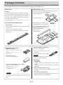
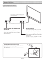
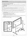
Copyboard
M-18S/M-18W
User’s Manual
Thank you for your purchase of the PLUS Copyboard.
Please read this User’s Manual carefully before use to take full advantage of the functions of this product. After you have finished reading
the manual, please keep it for future reference.
Introduction
This manual is for both the M-18S and M-18W models.
The copyboards come in two sizes: standard size (model M-18S) and wide size (model M-18W).
The descriptions and diagrams in this manual refer to the model M-18S.
* When functions or operations are specific to a certain model of copyboard, the model name is specified.
Trademarks
• Microsoft and Windows are registered trademarks or trademarks in the United States and other countries of the Microsoft
Corporation.
• Adobe, Adobe Acrobat Reader and Adobe Flash are trademarks of Adobe Systems Incorporated.
• Velcro is a registered trademark of Velcro Industries.
The trademarks of the various companies and the product trademarks, even when not written down, will be given due
respect.
Product names and company names appearing in this manual are registered trademarks or trademarks of the respective
companies.
(1)
(2)
(3)
(4)
(5)
The contents of this manual may not be reprinted in part or whole without permission.
The contents of this manual are subject to change without notice.
Great care has been taken in the creation of this manual; however, should any questionable points, errors, or omissions
be apparent, please contact us.
Notwithstanding Section (3), this company will not be responsible for any claims of loss or profit or other matters
deemed to be the result of using this unit.
The use of a printer as the peripheral device of the PLUS Copyboard is taken to be a prerequisite; therefore, operation
will not be guaranteed when the printer is used with a direct connection to a personal computer.
E-2
Table of Contents
Introduction ..........................................................................2
Package Contents ................................................................4
Names of the Parts ...............................................................5
Front ................................................................................5
Input/output terminals ........................................................6
Changing the Height of the Unit .........................................7
Control Panel .....................................................................8
Operation Steps ...................................................................9
Connecting the Power........................................................10
Printing (printer sold separately) .......................................11
Preparing the Printer ........................................................11
Basic Printing Operation ....................................................12
Moving the sheet surface manually ..................................13
Using USB Memory ............................................................14
USB Memory Storage Procedure .....................................14
Saving Image Files on a Computer/Deleting Image Files ...........16
Using the copyboard connected to a computer ...............19
Making the Device Settings ...............................................20
Meaning of Error Messages ...............................................23
Troubleshooting ..................................................................24
Specifications .....................................................................26
Appendix .............................................................................27
Connections and Wiring Diagram.....................................27
Meaning of the Terms Used in this Manual
• Main unit (or set): This refers to the copyboard.
• USB memory: refers to USB flash memory.
• USB memory storage: means the saving of sheet surface data using MEMORY (i.e., the USB port) of the
operation panel. (The Copyboard has 3 USB ports.)
• Internal memory: indicates a temporary saving location of the image that has been read.
• “copy”: Both “print” and “USB memory saving” mean to “copy.”
• “Sheet surface”: refer to the drawing portion.
• “Scroll” or “move”: indicates feeding of the sheet.
E-3
Package Contents
The package contents are as described below. Please check before use.
• Wall brackets (1 set)
Main unit [1]
These are brackets for mounting the main unit on a wall.
(See the Assembly and Setup Manual.)
Upper wall brackets: 2
Stand [1]
A mobile stand (with casters) for supporting the main
unit. A printer table and AC adapter box are included. For
the contents of the stand's package and instructions on
assembly, see the stand's instructions or the separate
Assembly and Setup Manual.
Lower wall brackets: 2
* Depending on the type of set you have purchased, some parts may
be sold separately.
Assembly and installation parts
Main unit fixing screws (M4 x 12: 2)
* Sold separately for some products.
• Pen tray (1)
• Wall mount printer table (1 set)
Pen tray fixing screws (M4 x 20) (temporarily fastened
on main unit)
M-18S: 3 screws, M-18W: 4 screws
(See the Assembly and Setup Manual for assembly
instructions.)
Bracket fixing screws (M4 x 8): 4
AC power adapter box: 1
Velcro: 2 sets
* Sold separately.
• USB cable (type B ↔ type A) [1]
[PLUS code 715258900]
Copyboard Accessories
• Dedicated markers
(One each of black, red, blue, and
green)
Use these markers to draw on the
sheet surface.
Cable for connecting the main unit to
a computer.
Used for making the device settings.
Notice
• Dedicated eraser [1]
Use this to erase the drawing.
Do not use this cable for connection
to the printer (sold separately).
Documents
• AC power adapter (with power cord) [1]
This is the power adapter for
supplying power to the copyboard (See Page E-10).
( LTE36E-S2-3)
Notice
The included AC power adapter and AC power cord are
exclusively for use with this unit. Never use them with other
products.
E-4
• CD-ROMl [1]
Includes the User’s Manual (this manual) in PDF
format.
The User’s Manual contains instructions on using the
copyboard.
• Important Safety Information [1]
Includes instructions to be heeded in order to use the
set safely.
• Assembly and Setup Manual
Includes instructions on installing the set and connecting it with the printer (sold separately).
Names of the Parts
Front
Main unit
Frame cover
Sheet
Dedicated markers are used on the sheet to
draw diagrams and to write.
Control panel (See Page E-8)
Pen tray
Input/output terminals
(see next page)
* Located on the bottom surface.
Printer table
The printer* is placed here. (See the Assembly
and Setup Manual.)
* The printer is sold separately.
AC adapter box
Store the AC power adapters of the copyboard
and printer here. (See the Assembly and Setup
Manual.)
* This illustration does not show the connection cords.
Stand
This stand supports the copyboard. (See the
Assembly and Setup Manual.)
* Depending on the product you have purchased, the printer may be
sold separately.
Effective Reading Size
The area that can be copied is the gray area of
the diagram.
approx. 5 mm
Note
approx. 10 mm
• It might not be possible to print or save
the portions that are drawn outside of the
effective scanning area.
approx. 10 mm
Effective reading size
approx. 5 mm
E-5
Names of the Parts
Input/output terminals
The connector is located on the bottom surface of the main unit.
The diagram view is seen from the bottom.
* This illustration does not show the printer or connection cords.
Personal computer (PC) dedicated USB
port (Type B)
DC input connector
Connect this with the DC plug end of the AC
power adapter. (See Page E-10.) (Only connect
the supplied AC power adapter; nothing else.)
Connect this with the USB port (type A) of the PC.
Used to connect the copyboard to a computer to
make the copyboard's device settings. Can also be
used to copy scanned images onto the computer.
(See page E-19,E-20)
Printer connector (USB port Type A)
Connect this with the USB connector of the printer
(See Page E-27).
(The printer connector is dedicated for use with a
printer; use it only with a printer.)
Locking/unlocking the stand's casters
After installation, lock the casters with the stoppers. When moving the stand, unlock the caster's stoppers.
The stoppers are locked when the bottom is pressed. Press the
top to unlock them.
Unlock
Lock
Caster
E-6
Names of the Parts
Changing the Height of the Unit
This is the height adjustment when setting up the copyboard on the optional stand. The stand height can
be adjusted to 3 levels by 100 mm.
CAUTION
• At least two persons should hold the main unit. If not, the main unit could drop or tip, resulting in accidental
injury.
• Lock the stand's casters by pressing the bottom of the caster lock button. If not, the stand could move while
the main unit is being mounted or removed, resulting in accidental injury.
• After unplugging the power cord from the wall power outlet, disconnect all the connection cords from the set's
input/output terminals. If the set is removed without disconnecting the cords, it could tip, resulting in accidental
injury.
• If a printer is mounted on the set, remove the printer before starting. If not, the stand could tip while the main
unit is being mounted or removed, resulting in accidental injury due to the printer dropping or tipping over.
(1) Unplug the power cord from the wall power outlet, then disconnect all the connection cords
from the main unit.
(2) Remove the locking knobs (one on each side).
(3) Change the position of the main unit support pieces.
Lift the main unit about 1 cm to unhook it.
Insert the stand's hooks securely into in the mounting holes in the main unit's support pieces (one on
each side).
(4) Fasten the two locking knobs (left and right) to the mount support pieces.
(5) Connect all the connection cables.
Rear frames
Mounting hole
Hook
lock-screws
lock-screw
Stand
* This illustration does not show the connection cords.
E-7
Names of the Parts
Control Panel
When pressing a button, please press the center area (the square bulge). The button may not work if it is pressed on a
corner.
2
1
ON/Standby
button
Turns the copyboard’s power on and off (standby mode).
2
The number of copies, operating status and error messages
are displayed on the 7-segment LEDs.
3
3
4
Number of Copies/Test print
button
Press this button to set the number of copies to be printed
(max. 10). The number of copies is displayed on the display
window.
*"
" is displayed during test printing.
5
6
4
Color Print
button
The sheet is moved by 1 screen and read, and the image
is printed in color in the number of copies indicated on the
display window.
7
5
B/W Print
button
The sheet is moved by 1 screen and read, and the image is
printed in black and white in the number of copies indicated
on the display window.
1
6
9
Save
button (USB memory storage)
The sheet is moved by 1 screen and read, and the image is
stored on the USB memory device.
When connected to a computer by USB cable, the image is
stored in the copyboard's internal memory.
8
7
Display
window
Display window
Meaning
USB Memory not
recognized
USB Memory storage
problem
USB memory not
connected
8
USB A Memory port (USB Type A)
Saves in commercially-available USB memory images that
have been read by the copyboard.
9
Off
On
On
Off
Status
These indicators light or turn off to indicate errors with the
copyboard, USB memory device or printer.
(See table at left)
Also check the error message on the display window.
For error information and remedies, see page E-23.
USB Memory is full
An unsupported printer
is connected
Warning that disconnec*
tion of USB memory has
been forgotten
Reading problem
System error
button
Scrolls the sheet one screen portion left, then stops automatically. A press of this button while scrolling will stop the
scrolling.
Copyboard Device
indicator
indicator
Printer problem
Scroll/Stop
Time setting error
* The letters "USB" scroll on the display.
E-8
Operation Steps
The copyboard uses a CIS (Contact Image Sensor) image sensor to read the diagrams and text that have
been written down with special (4-color) markers, and accumulates the image data in internal memory. The
sheet surface's image data is printed out from the printer when the Color Print ( ) or B/W Print ( ) button is
pressed, or stored as image data on the USB memory device or in the main unit's internal memory when the
Save ( ) button is pressed.
Preparation
• Set up the newly purchased copyboard and connect a printer.
See a separate manual titled “Assembly and Setup Manual.”
• Plug the AC power plugs of the copyboard and printer into wall power outlets. See page E-10.
• After purchase, be sure to set the copyboard's clock. If not, the proper date and time will not be displayed on
prints or in image files. See page E-21.
Draw on the Sheet Surface
Please draw with the dedicated markers that have been supplied.
If anything other than the dedicated markers or eraser are used, it may be impossible to erase the
sheet or the sheet could get dirty.
To move the sheet manually, see “Moving the Sheet Surface Manually” on page E-13.
Saving to USB Memory
(1)
Printing
(1)
(2)
(3)
(4)
(2)
Set A4 or letter size paper.
Do not set anything other than A4 or letter size
paper.
Press the ON/Standby
button of the copyboard and
switch on the power.
Switch on the printer power.
For instructions on operating the printer, see the
printer’s operating instructions.
Press the Color Print
or the B/W Print
button. The copyboard will move a one-screen portion of sheet, read the image, and start the copy
operation*.
See “Printing” on Page E-11.
(3)
Press the ON/Standby
button of the copyboard to switch on the power.
Insert USB memory into the Memory
port
(USB A port) of the copyboard.
Press the Save
button.
See “Using USB Memory” on Page E-14.
Saving on a computer
(1) Press the copyboard's ON/Standby ( ) button to
turn the power on.
(2) Connect the copyboard to the computer using the
PC dedicated USB port.
(3) Press the Save ( ) button.
(4) The image is saved on the computer.
When Not Using the Copyboard
(1)
(2)
(3)
By all means, cleanly erase the drawing from the sheet surface with the dedicated eraser. (Leaving the drawing for a
long period will make it harder to erase.)
Press the ON/Standby
button of the copyboard and switch off the power (standby mode).
The power cannot be switched off while the USB memory remains installed. (This is a prevention function against
forgetting to unplug the USB memory.)
Switch off the printer power.
Note
• When connecting the power plug, the flashing LED indicator in the display window starts to rotate for about 5 seconds.
Make sure to press the On/Standby
button to power on the copyboard when the flashing LED indicator goes off.
• The color of the images when printed in color or when saved in USB memory will differ somewhat from the marker colors.
• Blurred characters, thin lines, overlapping of markers and other factors can cause colors to differ in places and can also
result in portions that cannot be scanned successfully.
Also, black may be mixed in (for color prints) and ruled lines may be scanned.
• Data in the internal memory is cleared when the power is turned off (set to standby) with the power
button or when the
computer is disconnected.
E-9
Connecting the Power
Note
About the connection and the AC adapter box
Place the AC power adapters of the main unit and printer in the AC adapter box.
If you only have one power outlet, connect the AC power adapters of the main unit and printer to a commercially available cable tap, place them in the AC adapter box, and connect the cable tap's power plug to
the wall power outlet.
Also, if not connected or placed in the AC adapter box, see the separate "Assembly and Setup Manual"
and connect according to the purpose.
Wall outlet
Printer's AC power
adapter
AC adaptor box
Copyboard's AC power
adapter
* Be sure to insert all the plugs securely.
To use the copyboard, connect the copyboard's AC power plug to a wall power outlet.
The main power turns on. In this manual, this is referred to as the “standby mode”.
The descriptions in this manual assume that the AC power plug is connected (that the unit is in the standby mode).
About the printer's power supply
• When using a printer, connect its power plug to a wall power outlet.
Also, turn on the printer's power before printing.
When not using the copyboard for long periods of time
Disconnect the AC power adapter’s power plug from the AC power outlet in the wall.
Notice
• When the AC power adapter’s power plug is unplugged from the power outlet, place the copyboard near the power outlet so that it can be reached easily.
• The supplied AC power adapter and AC power cord are intended for exclusive use with this product. Never use them
with another product.
E-10
Printing (printer sold separately)
Use a printer to print out the image that has been drawn on the sheet surface. Use a PLUS-designated printer.
Operations and names of parts differ from printer to printer. For details of operations, see your printer’s operating instructions.
Preparing the Printer
Please check that the copyboard and the printer have been connected. See Page E-27.
Power switch
Set the paper.
Please use A4 or letter size printer paper.
• When using letter size paper, set letter size paper in
the device settings. (See page E-20.)
1) Arrange the paper edges so that they are even.
2) Insert paper at the specified position of the paper
tray.
3) Press the paper guide gently until it touches the
paper.
Paper guide
Note
See your printer’s operating instructions for a
description of the paper that can be used.
Paper
Paper tray
Discharge tray
Appearance of printer is for illustration
purposes.
Switch on the power.
Press the power switch. The power indicator lights.
This completes the preparation of the printer.
Press the Color Print
or the B/W Print
button on the copyboard’s control panel. One page worth of data is read and the printing
operation starts.
Note
• Depending on the printer, indicators, etc., may flash after the
power is turned until the printer is prepared to print. In this case,
see the printer’s operating instructions and check that the printer
is ready before starting the printing operation on the copyboard.
When finished printing...
Switch off the printer power and remove the paper.
Close the paper tray.
Notice
• Caution: Do not turn off the power or disconnect the USB cable
during printing.
E-11
Printing
Basic Printing Operation
Preparation:
Preparation: Check that the AC power plugs of the copyboard and printer are
connected to wall power outlets. See Page E-10.
Press the ON/Standby
button and switch on the power.
Prepare the printer. (See the previous page.)
Note
• When turning on the power, wait about 5 seconds after connecting the
copyboard's AC power plug to the wall power outlet or after turning off
the power (standby mode) before pressing the ON/Standby button.
• Press the ON/Standby button to switch on the power. The LED of the
display window will light.
• Turn on the copyboard’s power before turning on the printer’s power.
Press the Scroll/Stop
face you want to print.
button and display the sheet sur-
A press of the Scroll/Stop button scrolls the sheet surface one screen
portion left and automatically stops it.
To stop the operation part way through, press the Scrol/Stop
button again.
Note
• The one-screen that is visible is printable position.
• To fine-adjust the sheet surface position, with the sheet stopped,
move the sheet slowly by hand. The sheet can be moved either to
the left or to the right.
• Printing of the portion located around the sheet surface might not be
possible. Please see “Effective reading size” on Page E-5.
Press the Number of Copies
number of copies.
button and select the
Note
• "01" is selected when the power is turned on.
• Up to 10 copies can be specified and displayed on the display
window.
• The number of copies increases by 1 each time the Number of
Copies button is pressed, and "
" is displayed after "10" (this is
used for test printing). When the button is pressed again, the display
switches to "01". The number switches continuously if the button is
held in.
• After setting the number of copies, proceed to step 4 within 1
minute. The number of copies is reset to "01" if no operation is performed within 1 minute.
E-12
Printing
Press the Color Print
or the B/W Print
button to print.
or
• The reading operation is performed for a one-sheet portion (while the sheet is scrolled) and the printing operation is performed.
Cancellation of the print operation in progress
When the ON/Standby button is pressed, the reading of the sheet stops, and the partially read image data is printed.
Wait until the sheet is expelled from the printer.
Note
• If the ON/Standby button is pressed while the sheet surface is being read, printing is interrupted and only
part of the image will be printed.
To move the sheet surface, wait until scrolling stops, then press the Scroll/Stop
button .
• The one-screen portion is reduced to A4 paper size and printed.
For wide type copyboards (model M-18W), the image is compressed about 75% in the horizontal direction.
To print with the same proportions as the image on the sheet surface, see "Making the Device Settings" (page
E-20).
• A flashing “
” in the display window indicates a print error. See “Meaning of Error Messages” on Page E-23.
• When printing, a time stamp (date and time) is printed at the top right of the sheet. See "Making the Device
Settings" on page E-20.
When the copyboard is not going to be used, press the ON/Standby
off the power (standby mode).
button and switch
• Switch off the printer power.
Note
• If no button is operated within 30 seconds, the power turns off automatically (auto power off).
When the power is turned off, scanned images stored in the unit's internal memory are cleared.
• The auto power off function is canceled when the copyboard and computer are connected by USB cable.
Moving the sheet surface manually
The sheet can be moved even when the power of the copyboard is
switched off.
The sheet can be moved with your hand either in left or right. Please
place your hand at the vertical center and move the sheet slowly.
Notice
Quick movement can cause damage to the drive mechanism of the
copyboard.
E-13
Using USB Memory
The content of what has been drawn on the sheet surface of the copyboard can be saved in USB memory.
Later, the saved image can be read into a personal computer and made into a document of the proceedings of
the meeting, or affixed to a document.
Notice
• No USB flash memory device is included. When purchasing a USB flash memory device, pay attention to the following:
1. USB flash memory devices formatted in FAT16/FAT32 are supported. USB flash memory devices in NTFS format cannot be used.
2. USB flash memory devices protected by a security function cannot be used.
3. USB flash memory devices with a capacity of over 32 GB cannot be used.
4. If the USB flash memory device is divided into multiple partitions, only one partition can be recognized with this unit.
• See the PLUS website for more information on USB memory devices usable with this unit.
USB Memory Storage Procedure
Preparation:
Check that the copyboard's AC power plug is connected to a wall power outlet. See page E-10.
Press the ON/Standby
button and switch on the power.
Note
• When turning on the power, wait about 5 seconds after connecting the
copyboard's AC power plug to the wall power outlet or after turning off
the power (standby mode) before pressing the ON/Standby
button.
• Press the ON/Standby
button to switch on the power. The LED of the
display window will light.
Insert the USB memory device into the USB A Memory
port of the copyboard.
Notice
• Check the side (polarity) of the
USB memory device before
inserting it. Forcing it in the
reverse orientation will damage the USB A Memory port or
USB memory device.
• Be careful not to bump into the
USB memory device with hand
or body while it is mounted.
Doing so could damage the
USB memory device or USB A
Memory port.
E-14
Using USB Memory
Press the Scroll/Stop
button and display the sheet surface you want to store.
The procedure for displaying the sheet surface you want to store is the same as for printing.
See “Basic Printing Operation” on page E-12.
Note
• The one screen portion that is viewable will be saved in USB memory.
• Saving of the portion located around the sheet surface might not be possible. Please see “Effective reading size”
on Page E-5.
Press the Save
button to store.
Flashing indicator “rotates” sequentially during USB memory storage operation.
Display window
• The reading operation is performed for a one-sheet portion (while the sheet is scrolled) and USB memory storage starts after the scrolling completes.
The (5 second) flashing “US” display indicates that the USB memory has not been inserted. Please
insert the USB memory and then press the Save button.
A (5 second) flashing “FL” display indicates that there is insufficient free capacity to permit storage
in USB memory. The flashing display will stop when the USB memory device is removed. Replace
with a USB memory device having sufficient capacity.
See “Meaning of Error Messages” on Page E-23 for other error displays.
Note
• Depending on the USB memory, it may take time for recognition or it may take time for saving.
button is pressed during the reading operation, the reading operation will be discon• When the ON/Standby
tinued and the partially read image data will be stored in the USB memory.
To move the sheet surface, wait until scrolling stops, then press the Scroll/Stop
button.
• The date and time of the saved file will reflect the copyboard time setting. See "Making the Device Settings" on
Page E-20.
• When a certain amount of free capacity is not available in the USB memory, “FL” will be displayed when the
Save button is pressed. Also, when insufficient free capacity arises during saving, “FL” is displayed at that
point. Delete data, set the sheet surface back to the original status, then press the Save
button again.
• When the copyboard and a computer are connected by USB cable, the data is stored in the main unit's internal memory.
Removing the USB memory
Check that the flashing rotation of the display window has changed to
steady lighting and that the USB memory access indicator is not flashing,
then pull the USB memory straight out. (Please see your USB memory
manual for details.)
Notice
• Do not unplug the USB memory device during the USB memory storage
operation (i.e., during the rotating, flashing display in the display window), or while the access indicator of the USB memory device is flashing
because data will be destroyed.
E-15
Using USB Memory
When the copyboard is not going to be used, press the ON/Standby
switch off the power (standby mode).
button and
Note
• “
” letters appearing at one-second intervals in a moving display in the display window indicate that a
USB memory device is mounted. Unplugging the USB memory device will switch off the power. (A function
that serves as a reminder to unplug the USB memory device)
• When the copyboard and a computer are connected by USB cable, the auto power off function (which turns
the power off automatically) is canceled.
• Scanned images files stored in the copyboard's internal memory are cleared when the power is turned off (set
button or when the computer is disconnected.
to standby) with the ON/Standby
Saving Image Files on a Computer/Deleting Image Files
Examples of operations follow for saving the image files in the USB memory device to the hard disk of the personal computer,
and for deleting the folder when the USB memory capacity is full. (There are various methods that can be used for saving and
deleting including the use of Explorer.) See the instruction manual of your personal computer or the software that you are
using for information about using a personal computer.
The copyboard's folder on the USB memory device is named "CB_image". The images are stored in this folder.
Image files are named "PV-xxx.jpg" (JPEG files), where "xxx" is an assigned 3-digit number starting from 001 (ex.: PV-001.
jpg). For North American models only, image files are named “PV-xxx.pdf” (PDF files).
Note
The format in which the image files are stored can be set to "JPEG". For North American models only, image files are
stored in PDF format.
Plug the USB memory device into a USB port of
the personal computer
When connecting to the personal computer for the first
time, the installation of a USB driver is required. Follow
the instructions manual of the USB memory device that
you are using.
• Usually, with Windows XP/Windows Vista/Windows 7, the
standard driver is installed automatically and the copyboard
is identified as "Removable disk" in "My Computer" (or
"Computer").
E-16
Using USB Memory
Saving the image files of a USB memory
device to a personal computer
1. Open “My Computer (or "Computer")”
and from within, open the drive of the
connected USB memory device.
The folder named “CB_image” is the saved data of
the copyboard.
2. Store the “CB_image” folder in “My
Documents” or another location.
All of the data contained in “CB_image” will be
stored.
Drag to My Documents
Notice
Depending on the computer’s usage environment,
these operations may not work properly. This could be
the case for example:
• when several USB devices are connected simultaneously to the computer.
• when the USB device is connected to a USB hub or
when it is connected using an extension cable.
Deleting USB memory image files with the
computer
Before deleting important image files, be sure to save
them on the computer (as a data backup).
1. Open “My Computer (or "Computer")” and
then open the drive icon which shows USB
memory.
The folder named “CB_image” contains the memory storage
data of the copyboard.
2. Place the “CB_image” folder in the “Recycle
Bin”, right click on the icon and select
“Empty Recycle Bin” from the pull-down
menu.
All of the data contained in “CB_image” will be deleted.
Even when the entire folder is deleted, a new CB_image
folder will be created automatically when USB memory is
used again with the copyboard.
E-17
Drag to the Recycle Bin
Using USB Memory
Disconnect the USB memory
The disconnecting procedure depends on the computer’s operating system. For details, refer to the computer’s operating instructions or help files.
1.
Click the [Hardware Removal]
played in the task tray.
icon that is dis-
Click “Stop USB Mass storage Device - drive (E)”. (The E
drive character will differ depending on the personal computer
system.)
2.
Click [OK] when “The ‘USB Mass storage Device’
device can now be safely removed from the
System” is displayed.
(When using Windows XP/Windows Vista/Windows 7, [OK]
does not appear on the message screen. Simply disconnect. )
3.
This allows the USB memory device to be
unplugged from the computer.
Note
• Do not disconnect the USB memory device while the USB
memory device’s access indicator is flashing. Doing so will
damage the data.
• The USB drive may not be disconnected properly, for example
if the computer is in the process of checking the status of
peripherals.
E-18
“Remove hardware” icon (example)
Using the copyboard connected to a computer
When the copyboard and a computer are connected by USB cable, the copyboard is recognized as an
external memory device (removable device). Below is the procedure for copying the "CBImage.JPG" file from
this device onto the computer. The format in which the image files are stored can be set to "JPEG". For North
American models only, image files are stored in PDF format.
Notice
• Only one sheet’s worth of data can be stored in the copyboard’s internal memory.
When the storage procedure is performed successively on the copyboard, the data is overwritten.
• The image data in the copyboard's internal memory is cleared when the USB connection between the copyboard and
computer is cut off.
• Do not save data from a computer into the copyboard's internal memory.
• The copyboard's internal memory cannot be formatted from a computer.
• Do not disconnect the USB cable or access the copyboard while the data is being saved after pressing the copyboard's
Save ( ) button/. Doing so may cause operation of the computer to become unstable.
• Do not press any operation buttons on the main unit while the copyboard's internal memory is being accessed from the
computer. The response time could be long and the operation may not be possible.
Turn on the copyboard's power and connect the PC dedicated USB port (type B) and computer using the USB cable.
• Usually, with Windows XP/Windows Vista/Windows 7, the standard driver is installed automatically and the copyboard is identified by the computer as a removable device.
USB cable included
with copyboard
To computer's USB
port (type A)
To PC dedicated
USB port (type B)
On the computer, open "My Computer", and
from there open the copyboard identified as a
removable device.
(1) Double-click the "My Computer" (or "Computer") icon to
open it.
(2) When the device icon for the copyboard (displayed as a
removable disk) is double-clicked, the copyboard’s internal memory opens.
The "CBImage.jpg" file is the scanned image file.
- The "setup" folder contains the copyboard settings file.
- To check the copyboard’s operation as a device, rightclick [My Computer] (or [Computer]) to display the menu,
then at Administration -> Device Manager in Windows 7
(Properties -> Device Manager in Windows XP), check
that "PLUS Copyboard USB Device" is displayed as the
disk drive name.
(3) Copy the "CBImage.jpg" file to [My Documents], etc., on
the computer.
To disconnect the USB cable, follow the procedure in step 3
on the previous page.
E-19
Drag to My Documents
Making the Device Settings
Make the copyboard’s device settings (paper size, aspect ratio setting and time setting) using a computer.
When the copyboard and a computer are connected, the copyboard is recognized as an external memory
device (removable device).
Notice
• Do not save data from a computer into the copyboard's internal memory.
• The copyboard's internal memory cannot be formatted from a computer.
• Do not disconnect the USB cable or access the copyboard while the data is being saved after pressing the copyboard's
Save ( ) button/. Doing so may cause operation of the computer to become unstable.
• Do not press any operation buttons on the main unit while the copyboard's internal memory is being accessed from the
computer. The response time could be long and the operation may not be possible.
Before making the device settings
The copyboard’s device settings screen is created using Adobe® Flash®. Settings are made by opening a web browser.
Because of this, a web browser and Adobe Flash Player 10 for displaying the device settings screen must be installed on the
computer. If Adobe Flash Player 10 is not installed on the computer, download it (free of charge) from the Adobe website.
Turn on the copyboard's power and connect the PC dedicated USB port (type B) and computer using the USB cable.
• Usually, with Windows XP/Windows Vista/Windows 7, the standard driver is installed automatically and the copyboard is identified by the computer as a removable device.
USB cable included
with copyboard
To computer's USB
port (type A)
To PC dedicated
USB port (type B)
Open [My Computer], and from there open the copyboard identified as a removable device.
(1) Double-click the "My Computer" (or "Computer") icon to open it.
(2) When the device icon for the copyboard (displayed as a removable disk) is double-clicked, the copyboard’s
internal memory opens.
- To check the copyboard’s operation as a device, right-click [My Computer] (or [Computer]) to display the
menu, then at Administration -> Device Manager in Windows 7 (Properties -> Device Manager in Windows
XP), check that "PLUS Copyboard USB Device" is displayed as the disk drive name.
Open the "CBSetup" file in the "setup" folder.
(1) Double-click the "setup" folder to open it.
(2) Open the file in the "setup" folder with your web browser.
* With Internet Explorer, a security warning may appear. To cancel it, see page E-22.
* Depending on the browser’s version, etc., the file may not open. In this case, open the "setting.ini" file (in text
format) using Notepad or another application on the computer and rewrite the contents of the settings file
directly. (See page E-22)
E-20
Making the Device Settings
Make the device settings and save the "setting.ini" settings file, overwriting the previous file.
(1) Make the settings.
Settings:
For the paper size and aspect ratio, click the radio button
for the desired item to select it.
Time Day Stamp:
For the time day stamp, use the computer's number keys to
input the current date and time.
(2) If you have changed the copyboard's device settings, click
the "Set" button for the "Settings" section.
If you have changed the date/time setting, click the "Set"
button for the "Time Day Stamp" section.
(3) The save file screen appears when one of the "Set" buttons
is pressed. Save the "setting.ini" file (overwriting the previous file) in the following location:
Save to location: "setup" folder for the copyboard (removable disk)
File name: setting.ini
(4) Close the web browser.
This completes the device settings.
Item Name
Paper Size
Printing Image
Time Day Stamp
Description
Default Setting
Sets whether to print on the printer in A4 or letter size.
North America: Letter
A4 size printing range: Equal ratio – 145 x 287, Compressed – 195 x
Others: A4
287
Letter size printing range: Equal ratio – 136 x 269, Compressed – 206
x 269
This is only selectable on wide type copyboards.
Match Paper Size
This selects the vertical:horizontal aspect ratio of the image when
printing.
Original Image: Image is printed with the same aspect ratio as on the
copyboard's sheet surface.
Match Paper Size: Image is compressed horizontally to the A4 or letter size paper's aspect ratio (ex.: circles become
ovals).
Input the current date and time.
The entry fields are as follows (in order): Year / Month / Day / Hours:
Minutes
Input as follows:
Year: 4 digits, Month: 2 digits (ex.: 03 for March),
Day: 2 digits (ex.: 06 for the sixth),
Hours: 2 digits in 24-hour format (ex.: 14 for 2:00 pm, 06 for 6:00 am),
Minutes: 2 digits (ex.: 00 for 0 minutes)
* Do not input spaces. If this is done, the file will be recognized as corrupt when the copyboard is started and the settings well be reset to
the defaults.
Get Current Time :
When “Get Current Time” button is clicked, the display switches
to the computer’s current time. This eliminates the need to set the
current time on the copyboard.
E-21
Making the Device Settings
Note
Rewriting the "setting.ini" settings file directly
Depending on the browser’s version, etc., the file may not open. In this case, open the "setting.ini" file (in text format)
using Notepad or another application on the computer and rewrite the contents of the settings file directly.
Description example:
Date=2011/02/03
Time=00:00
A4Page=0
Stretch=1
Item
Item
Date
Time
Paper size
Printing Image
Date
Item Name
Setting Value (numbers to be input)
Date
Current date
Time
Time
Current time (24-hour mode)
Paper size
Printing
Image
A4Page
Stretch
Set to "0" for letter size, "1" for A4 size.
Set to "0" to print the image as it is on the
sheet surface.
Set to "1" to fit the image to the printing
paper.
Restrictions
Use "/" to separate the year, month and
day.
Use ":" to separate the hours and
minutes.
Only settable for wide type copyboards
* See the previous page for details on the settings.
* Do not input spaces. If this is done, the file will be recognized as corrupt when the copyboard is started and the settings
well be reset to the defaults.
(1) After the file has been rewritten, save it, overwriting the previous "setting.ini" settings file.
Save to location: "setup" folder for the copyboard (removable disk)
File name: setting.ini
(2) This completes the device settings.
• Canceling the Internet Explorer security warning
If a security warning is displayed when the device settings file is opened with Internet Explorer, it can be canceled using
the procedure below.
The explanation in this example is for Windows XP.
(1) Click the warning bar.
A pop-up menu appears.
(2) Click "Allow blocked content (A)...".
The security warning screen appears.
(3) Click "Yes (Y)".
This cancels the warning. The device settings file opens.
E-22
Meaning of Error Messages
If any of the following flashing indications appear in the display window of the
control panel, please check the matters described below.
Error messages flash for 5 seconds, then stop flashing, remaining lit.
Error Display Number
Printer not
connected
No printing
paper
Printer problem
Problem and Solution
• Is the printer cable connected?
• Connect the printer properly and switch on
• Is power being supplied to the printer?
the printer power.
• When the printer uses an AC power adapter, is the cable disconnected somewhere?
• Has paper been set in the printer?
• Turn the power of the printer off and then on
again, and load the printer with A4 or letter
size paper.
• Is the printer error indicator flashing (or • Read the printer instruction manual.
lit)?
USB Memory
not recognized
• Is the USB memory unformatted.
• This unit supports the FAT and FAT 32
formats. Perform the formatting with the
personal computer.
• Is a USB memory that is not supported by • Please see our home page for information
the copyboard being used?
about USB memories that can be used
with the copyboard.
• Is the USB memory device plugged in • Please check the operation with a personal
fully?
computer.
• Is the USB memory damaged?
USB Memory
storage
problem
• An error occurred during USB memory • Please perform USB memory storage
storage.
again.
• Do not insert or remove the USB memory
during processing.
Reading
problem
• There is a lighting fault of the reading light • Unplug the power plug from the power
source, or a read signal error.
outlet and then plug it in again.
System error
• There is a memory or internal fault.
USB memory
not connected
• USB memory device is not plugged into • Plug the USB memory device into the USB
the main unit.
port.
USB Memory
is full
• There is no available space.
An unsupported printer
is connected
Time setting
error
• Unplug the power plug from the power
outlet and then plug it in again.
• Please delete unnecessary data using a
personal computer (See Page E-16).
• A printer that is not supported by the • Press the ON/Standby
button and
copyboard has been connected.
switch off the power. When a record is
required, switch on the power and save to
USB memory.
• An error has arisen when setting the time.
• Start setting the date/time over from the
beginning.
• Did you press the ON/Standby
but- • A USB memory device is plugged into
When the “USb” letter diston while the USB memory device was
the main unit. When the USB memory
play is flowing...Warning that
plugged into the main unit?
device is disconnected, the power will
disconnection of USB membe switched off and the unit will enter the
ory has been forgotten
standby mode.
If the problem persists, please contact your nearby PLUS Corporation sales office, dealer, or store.
E-23
Troubleshooting
Please check the following matters before making a request for servicing.
Condition
Copyboard Related
Pressing the ON/Standby
not switch on the power.
Please Check
button does • Check whether the cable of the AC power adapter is disconnected from
the DC connector of the Copyboard or the wall outlet. (Unplug the AC
power cable from the outlet, wait several seconds and then plug it back
into the outlet again.)
Writing on the sheet is not erased with • Was a marker other than a dedicated marker used?
the eraser.
Portions of writing or lines are not printed • Portions of blurred characters or thin lines may not be printed or stored in
or stored in memory.
USB memory.
Scanned copy (image) is dirty, Erase • Is there marker residue or substantial quantities of refuse on the sheet?
(If the sheet is dirty, moisten a soft cloth with water, wring well, then wipe
Reminder function is activated even when
the sheet in a stroking manner.)
sheet is erased with the eraser
When the copyboard and PC are con- • Check whether the copyboard is in an operable condition, and whether
the USB cable is connected properly.
nected, the PC does not recognize the
• Is the copyboard connected to the PC via a USB hub?
copyboard
(Connect the copyboard directly to the USB port of the PC.)
The date is not updated.
• The copyboard's battery is dead. Contact your store of purchase.
* If the problem persists, please contact your nearby PLUS Corporation sales office, dealer, or store.
Condition
Please Check
Printer Related
The copyboard's power turns on, but the • Check whether the printer's power plug (DC plug) is securely inserted.
printer's power does not.
If the power still does not turn on, disconnect the AC adapter box and
check whether the printer's AC power adapter side plug is unplugged
from the AC power adapter. (For some printers it is directly mounted.)
A press of the Print button does not result • Check that the power cable of the printer and the printer cable are
in printing.
securely connected.
• Check that the printer power indicator is lit.
• Check that the error indicators of the copyboard and the printer are not
lit.
• If the error indicator of the copyboard is flashing, please see Page E-23.
(Please see the printer instruction manual for information about printer
errors.)
The paper feed is abnormal.
• Possible causes include damp paper, overly thin or thick paper, only one
sheet of paper is set, and a curved setting of the paper. (Please see the
instruction manual for your printer.)
An altered color is printed, not the speci- • Please replace the print cartridges with new ones.
fied color.
There is no printing.
• Check that the print cartridge is properly set.
• Check that the print cartridge is not plugged.
∘ Print is very pale, there are white lines Is the print cartridge’s nozzle partially choked?
on it, or page is dirty.
◆ Make a test print and check the conditions of the nozzle.
∘ Printed colors are very different from
those of the markers that were used.
Continued on next page
E-24
Troubleshooting
Test Printing
1) With the copyboard's power on (with the display window lit), press the Number of Copies button repeatedly to display
"
" on the display window.
2) Press the Color Print ( ) button for a color print, the B/W Print (
) button for a black-and-white print.
* Test printing starts.
Check the print
• Is the each color line printed uniformly?
• Are there missing dots, pale lines, lines with thinner ink than others, etc.?
Remedy
◆ If the nozzle is partially choked, clean it.
◆ If the quality of the print does not improve even though the nozzle has been cleaned, wipe off the ink on the surface of
te nozzle.
For details, see the “User’s Guide” included with the printer.
* Please see your printer manual for information about printing problems, printer maintenance, and details related to printing.
E-25
Specifications
BOARD TYPE (Model name)
Standard (M-18S)
Installation method
Form
External dimensions
(T-shaped legs*¹)
Main unit weight
Wide (M-18W)
Self-standing (T-shaped legs), or wall mounting
W1480 × D675 × H1947*² mm
20 kg*³
25 kg*³
T-shaped legs weight
12.5 kg
Panel Size
H910 × W1300 mm
Effective reading size
H900 × W1280 mm
H910 × W1800 mm
H900 × W1780 mm
Number of Pages
Paging
2
Endless in one direction (Horizontal scrolling)
Drive method
BOARD
Sheet movement
Reading method
CIS (Contact Image Sensor)
Reading illumination light
source
Reading resolution
Reading time
File format
Board
Screen size
RGB LED
Main scanning direction (vertical sheet surface) 1.92 dots/mm (50 dpi or equivalent)
Sub scanning direction (horizontal sheet surface) 1.92 dots/mm (50 dpi or equivalent)
Black & white: approx. 15 s
Color: approx. 15 s
Interface
Printing
Added functions
Miscellaneous
FAT 16, 32
Interface
USB1.1 or USB2.0 *5
Printing resolution
300 dpi or equivalent
No. print colors
16 or grayscale
Printer interface
Conforming to USB 2.0 standards
Clock
AC power adapter
Power consumption
Operating
conditions
USB Flash memory
Compatible FAT
types
PC connection
Power supply
Black & white: approx. 21 s
Color: approx. 21 s
JPEG format (or PDF format*4)
Standard type: 2458 x 1728 dots (fixed)
Wide type: 3418 x 1728 dots (fixed)
Type
External
memory
W1980 × D675 × H1947*² mm
Used for the timestamp and for file dating properties
(Includes backup battery for when there is a loss of power. Battery life: Approx. 00 hours)
Images can be acquired and device settings made via USB (using a browser)
Input : AC100–240V/50–60 Hz, Max 0.75 A
Output : DC 12 V, 3.0 A
In standby: 3W, During operation: 12W (not including printer)
Temperature:
10–35°C
Humidity:
30–85% (No condensation)
Ruled lines
Miscellaneous
OS
Operating
environment
Web browser
50 mm cross-ruled squares
Dedicated markers (black, red, blue, and green)
Fully IBM PC/AT compatible computer equipped with standard USB port.
XP (Home Edition /Professional Edition, Service Pack 3 or greater)/
Vista (32-bit version) / Windows 7(32-bit/64-bit)
Or, Apple Macintosh computer with standard USB port
Mac OS X 10.5 or greater
Windows:Internet Explorer 8.0 or greater
Macintosh:Safari 5 or greater
* Enable JavaScript.
* With Adobe Flash Player 10 installed
Remarks
*1: The height is adjustable at 1747, 1847 and 1947 mm.
*2: The value indicated for “H” (height) is the maximum height.
*3: Not including the weight of the printer.
*4: North America Only.
*5: USB memory device not included. The memory capacity corresponds to 32GB or less.
• Please note that for quality improvement purposes, specifications and design are subject to change without prior notice.
E-26
Appendix
Connections and Wiring Diagram
The connections and wiring diagram below is included here for checking the connections.
[Copyboard and Printer Connections Diagram]
Copyboard front panel
To Printer connector
To DC INPUT connector
USB cable (supplied with the printer)
To USB connector
Printer
To DC connector
Printer AC power adapter
(supplied with the printer)
AC power adapter (supplied)
To wall power outlet
* Appearance of printer is for illustration purposes.
Note
The AC power adapters of accessories and printers that have been verified to be operation many differ from the ones
shown on the connections diagram (they may be of the built-in or mounted-on type).
E-27
26-4601-11B