1
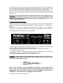
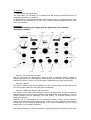
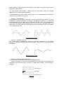
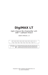
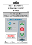
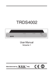
Xpass Filter User Manual v 1.0
Congratulations !
… and thank you for buying the Analog-Lab Xpass Filter. Before to go further in this user
manual, you just have to read carefully all the recommendations concerning the safety and
installation instructions.
I- Safety and installation recommendations
II- Introducing the Xpass Filter
III- Wiring and audio configurations
IV- Functions
- General view
- Section A / Vu-meter and input level
- Section B / Bypass
- Section C / Waveforms selector and modulations
- Section D / Lfo frequency
- Section E / Modulation Amount
- Section F / Filtering modes & Xpass zone
- Section G / Resonance
- Section H / Cutoff frequency
- Section I / Attack-Release
- Section J / Output level
- Section K / Headphones
V- Warranty
VI- Analog-Lab contacts
VII- Blank sheet
VIII- Personal notes
I- Safety and installations recommendations
- Use only the Xpass Filter with the supplied power supply. If you need any other power
supply, contact the Analog-Lab services which information are in the sixth paragraph of this
user manual.
- The Xpass Filter doesn’t have a on/off switch. Only the power supply is needed to switch
on the Xpass Filter.
- In any case, you won’t need to open the Xpass Filter. None of the intern components can
be manipulated by the user. Only the Analog-Lab technical staff is able to make technical
interventions. This is a condition of warranty canceling.
- Take care to install the Xpass Filter on a flat and free workspace, to avoid moisture or
humidity and shock risks.
- In its use, take care with the potentiometers and switches.
- The Xpass Filter is an instrument that generates very powerful harmonics that can damage
audio hardware. Take care with your settings: the headphones and the « cue » functions can
avoid you bad surprises for your monitors and your audience.
II- General view
The Xpass Filter is a very powerful filter built only with analog technology, so important for
our ears and musicality. It permits you to make a lot of different works on the frequencies,
form the very thin work on frequencies to tremendous and creative effects. The Xpass Filter
is a mono filter that accepts all the stereo sources. Both sides of the stereo will be mixed
before the filtering unit. All the sound levels are accepted: instrument, line and phono.
You can plug guitar, bass, electromechanical keyboards (Rhodes,Wurltizer, Clavinet, etc),
analog or numeric synthesizers, samplers, expanders, track recorder, cd players, turntable,
computer, etc.
Important: You’ll find many different audio levels with the cds. You’ll just have to
compensate this different levels with the input and output potentiometer. This
concerns principally the manipulation that consists in switching vinyl or cd in a
parallel wiring configuration.
III- Wiring and audio configurations
Whatever you plug in the Xpass Filter, there are generally two ways of wiring the Xpass Filter.
The first way consists in plugging the Xpass Filter in serial: Sound source → Xpass Filter →
Monitor
The second one consists in plugging the Xpass Filter in parallel, via the send/return
connections on your mixing console. The level adjustment will be easier in the serial mode.
Concerning the inputs, the Xpass Filter is fully equipped :
- A phono input with RCA plugs that drives the source to a high quality RIAA preamp with a
perfect equalization correction to optimize the vinyl sound.
- A line input (¼’ jack) that accept mono or stereo plugs to wire all line level sources.
- An instrument input (¼’ jack)
- A 0-5 volts (¼’ jack) for a tension command to use with a midi/cv converter or a pedal for
example. By this way, you can pilot the cutoff frequency of the filter.
- An output (¼’ jack) that permits to send a « pseudostereo « .
Important: to plug a stereophonic peripheral in the Xpass Filter, try to use a « Y »
¼’ jack as shown below. To connect the Xpass Filter to your monitoring system,
try to use the same type of wiring.
If you use a « vintage » analog synthesizer for example, you can plug it with a
mono ¼’ jack in the line input. The guitar and bass type instruments have to be
plugged with a ¼’ mono jack. If you want to use a microphone, you just have to
preamplify it. The preamp has to be plugged in the line input.
You’re now ready to use the Xpass Filter !!!
IV- Functions
y General view of the Xpass Filter:
The Xpass Filter is a well built unit in painted steel and brushed anodized aluminum. Its
mechanical conception is a solid one.
Its dimensions are 216mm/132mm/85mm and its weight is 1600 gr. The power supply is 250
gr. Weight. Its characteristics are 15 volts / 500 or 800 mA with an adapted tension for each
country or continent.
Important:
Use only the supplied power supply with the Xpass Filter. It’s a warranty
cancellation condition.
y Section A / Vu-meter and level input
With its technology, the Xpass Filter needed to have a traditional analog vu-meter. It
indicates the input level, considering that we can apply a 10% tolerance. It’s back lighted, to
indicate the power on of the unit. The level input is adjusted by the rotary potentiometer.
y Section B / Bypass
This switch is used to cancel all the parameters of the unit except the input and output levels.
The sound source passes thru the Xpass Filter transparently.
y Section C / Waveforms selector and modulations
This selector is one of the most important element of the Xpass Filter. It’s used to select the
modulation mode on the frequency treatment (described further in the Section F). It a fourposition selector with two waveforms (sine and square), an envelope follower and an
attack/release mode.
Reminder: Lfo is an abbreviation of « low frequency oscillator » that is a cyclic waveform
control which frequency determines its speed. In the case of the Xpass Filter, this speed is
variable with the lfo frequency potentiometer. The lfo gives expressivity in all the sound
design works or the musical movements.
The envelope follower is a mode that permits to apply the frequency treatment on the signal
audio waveform. The expressivity and reactivity of this mode is impressive and permits to
apply very creative effects.
The attack/release mode permits, in relation with the sound level, to apply the frequency
treatment with a variable attack and release.
These descriptions are quite abstract on the paper but you’ll understand and ear all these
modes uses and subtleties very quickly.
y Section D / Lfo frequency
If you choose to work on the lfo mode (sine or square), this potentiometer permits to slow or
accelerate the waveforms period by increasing or decreasing its frequency. If you turn right
the potentiometer, the lfo speed will be accelerated. Like the others, this potentiometer is
very precise and sensitive. At the beginning of its course, there is a « no speed zone », very
useful when you need to cancel the speed effect in quick manipulations. Here’s an illustration
of this frequency variation.
Modulation frequency variation
y Section E / Modulation Amount
The « Mod Amount » potentiometer adjusts the amplitude modulation: it’s the distance
between the lowest and highest point of the modulation. This function is used on all the filter
modulations.
Modulation amplitude variation
y Section F / Filtering modes & Xpass zone
The Xpass Filter is a multimode filter. Each mode detailed below:
- Hipass mode (Hp): it permits to let the frequencies to pass above a point filtering the
frequencies below this same point. This point is variable and it’s called « cutoff frequency »
(Section I)
Hipass Filter
- Lowpass mode (Lp): contrarily to the hipass mode, it lets the frequencies to pass below
the cutoff point and it’s filtering the frequencies above.
Lowpass Filter
- Bandpass mode (Bp): this filtering mode permits to a central frequency field to pass and
the frequencies above and below it are filtered.
Bandpass Filter
- Notch mode: contrarily to the bandpass mode, it filters a central field of frequencies to
pass the above and below frequencies of it.
Notch Filter
These four filtering modes are representing the complete panel of frequencies filtering and
permit an exhaustive panel of settings. We organized the filtering modes around a
potentiometer called « Xpass » and a commutation switch called Bandpass. But we have gone
further this idea…
The potentiometer called « Xpass » is a new and very important function on this product.
Turned completely on the left, the Xpass Filter is in lowpass mode (Lp). If you turn it
completely on the right, it applies the hipass mode. All the potentiometer course between
permits progressively to go from the lowpass filter mode to the hipass filter mode. This
characteristic is an Analog-Lab exclusivity, very powerful, creative and allows very musical
transitions.
The commutation cap below (called bandpass) permits to switch from the bandpass mode to
the notch mode described above. The Xpass potentiometer takes its place when the filter is in
bandpass mode (highlighted led). When you switch off this led , you are in notch mode and
the Xpass potentiometer is no more active.
- Section G / Resonance
The resonance is an harmonics generator. It permits to affect the sound very particularly and
creatively. Try to adjust this parameter very progressively. The resonance is very powerful
and, if it’s used excessively, it could saturate and even damage audio hardware.
- Section H / Cutoff
The Cutoff potentiometer permits to set the famous point around the frequencies are filtered
or not. It’s obviously variable as seen on the Section F.
- Section I / Attack-Release
These two parameters are specially destined to the A-R mode on the central rotary selector.
It permits to work on the two most important parameters of the envelope. It’s a very creative
function that allows variable « gate effects » especially on rhythmic patterns.
- Section J / Output level
The output level is also adjustable. Between the input level, the output level and the bypass
function, you can equilibrate the sound level of the original source and the « Xpass-ed »
result.
- Section K / Headphones
In this section, you can find a headphones level potentiometer, a cue switch, a led that
indicates the cueing activity and the ¼’ jack plug for your headphones. As soon as you switch
on the cue function, the audio output of the Xpass Filter is cut and no sound will be heard on
your monitoring system. Only the headphones can make you hear your Xpass Filter settings.
The headphones level potentiometer does not affect the main output level. That allows to
conserve the output level setting. When you switch the cue off, the signal passes in the main
output level and the headphones too.
V- Warranty
The Analog-Lab Xpass Filter have a one year warranty. This warranty is available if only the
product has been used in normal conditions. The warranty is limited on the replacement of
damaged parts. A cancellation of warranty could be applied if the Analog-Lab technical staff
observes any modification, replacement part, technical intervention or if the product has been
opened.
VI- Contacts
Analog-Lab
Prologue
Av. La Pyrénénenne
BP27201
31672 Labege / France
Tel. +33(0)5 61 52 50 68
Fax +33(0)5 61 52 63 71
Website: http://www.analog-lab.com
Informations: [email protected]
Emails:
Tech support: [email protected]