1
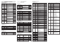
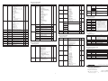
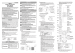
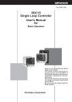
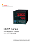
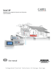
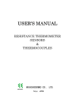
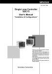
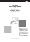
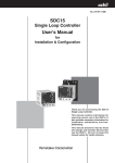
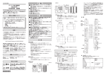
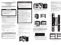
• WARNING (unit: mm) Note that incorrect wiring of the SDC25/26 can damage the SDC25/26 and lead to other hazards. Check that the SDC25/26 has been correctly wired before turning the power ON. Before wiring, or removing/mounting the SDC25/26, be sure to turn the power OFF. Failure to do so might cause electric shock or faulty operation. Do not touch electrically charged parts such as the power terminals. Doing so might cause electric shock. Do not disassemble the SDC25/26. Doing so might cause electric shock or faulty operation. ev2 ev3 sp ■ Unpacking Check the following items when removing the SDC25/26 from its package: Name Part No. Q'ty Remarks Mounting Bracket 81409654-001 2 User's Manual CP-UM-5288E 1 This Manual SAFETY PRECAUTIONS Warnings are indicated when mishandling WARNING this product might result in death or serious injury to the user. ■ Location Install the controller in the following locations: · Common mode voltages for I/O except power supply and relay contact output: The voltage to ground is 33Vr.m.s max., 46.7V peak max., and 70Vdc max. · Not high or low temperature / humidity. · Free from sulfide gas or corrosive gas. · Less dust or soot. · Appropriately processed locations to prevent direct sunlight, wind or rain. · Less mechanical vibration and shock. · Not close to the high voltage line, welding machine or electrical noise generating source. · The minimum 15 meters away from the high voltage ignition device for a boiler. · Less effect by the magnetic field. · No flammable liquid or gas. ■ Mounting Procedure · The mounting must be horizontal within 10 degrees tilted in back side lowering or within 10 degrees tilted in back side rising. · The mounting panel should be used with a thickness of less than 9 mm of firm board. ■ External Dimensions • C25 (unit: mm) 5 Cautions are indicated when mishandling this product might result in minor injury to the user, or only physical damage to this product. 48 enter Handling Precautions To fasten this controller onto the panel, tighten a mounting bracket screws, and turn one more half turn when there is no play between the bracket and panel. Excessively tightening the screws may deform the controller case. ■ Panel Cutout Dimensions (unit: mm) SDC25 sp out man mode ev1 ev2 ev3 ot1 ot2 display enter para 1 ● Connection of C25/26 Power supply Stand-alone mounting +0.5 0 (48xN–4) 92 44 +0.5 0 30 min. Gang-mounting +0.5 0 +0.5 0 1 AC power supply 100 to 240Vac 2 13 14 15 2 Event outputs Relay • C26 Gang-mounting Stand-alone mounting (96xN–4) +0.5 0 +0.5 0 92 +0.5 0 92 30 min. Control outputs 1 DC power supply 24Vac/24Vdc (non polar) Relay (independent contact) Current Transformer inputs 3 1 13 2 2 14 3 15 4 16 5 17 6 18 7 19 8 20 Inputs 9 21 7 8 9 10 22 11 23 12 24 3 4 5 6 1 COM 3 4 5 6 2 1 CT1 CT2 Handling Precautions • When three or more units are gang-mounted horizontally, the maximum allowable ambient temperature is 40°C. + C A Wiring Be sure to provide a switch within operator reach for shutting OFF the main power supply to the controller in the main supply wiring. Also, in case of AC power supply models, the main supply wiring also requires a time-lagged type (T) fuse (rated current: 0.5A, rated voltage: 250 V). (IEC127) The following table shows the meaning of the symbols in the terminal wiring label on the controller side: Symbols Meaning AC power supply DC power supply Caution, fear of electric shock Caution mA Voltage V Voltage pulse 2+ Current/Voltage pulse 13 14 13 14 15 Voltage pulse + 1– + – Current Current + – 2+ 1 Current Auxiliary output + – 4 3 2 1 COM Current 18 19 Digital input 20 21 Communication + Current 13 14 15 + – DI 10 11 12 B RTD Relay NC 13 14 10 11 12 – Thermocouple NO 16 17 PV inputs Handling Precautions • Before wiring the SDC25/26, verify the controller's model No. and terminal Nos. written on the label on the side of the body. Inspect all wiring once wiring work for the SCD25/26 has been completed. • Use M3 crimp-type terminal lugs for wiring to terminal. • Provide a distance of at least 50cm between I/O lead wires or communications lead wires and power lead wires. Also, do not pass these lead wires through the same piping or wiring duct. Terminal screw M3 • Be careful not to allow any crimp-type terminal lugs to touch adjacent terminals. • Prepare a heater current conductor to send a heater current through the current transformer. Do not use a heater current that exceeds the specified permissible current as this may damage the controller. • The current transformer input cannot be used for phase control. • There is no isolation provided between control output 1 and control output 2. Install an isolator as required. • Do not connect a terminating resistor to either end of the RS485 communications line. Doing so may interfere with communication. • Regarding a device or equipment which is connected to this controller, use a model to which the basic insulation meeting with the power supply voltage and the maximum operating voltage of the I/O units is provided. • The controller requires maximum 6 seconds to start up once the power is turned ON. The controller can be used once it has started up. However, it is recommended to allow a warm-up time of at least 30 minutes to attain the specified accuracy. • C25 65 Mounting bracket (Accessory) pv 96 CAUTION display para 30 min. This manual explains the handling precautions, mounting, wiring, PV range type, list of parameters and main specifications only. See the separate "Installation & Configurations" manual listed below for the detail handling procedures and the setting methods, etc. These manuals also contain information on using various functions. Please read if necessary. SDC25/26 Single Loop Controller User's Manual for Installation & Configuration CP-SP-1149E SLP-C35 Smart Loader Package for SDC15/25/26/35/36 Single Loop Controller User's Manual CP-UM-5290E mode Mounting 108 2003 Yamatake Corporation ALL RIGHTS RESERVED out ot2 +0.5 0 Ensure that this User's Manual is handed over to the user before the product is used. Copying or duplicating this User's Manual in part or in whole is forbidden. The information and specifications in this User's Manual are subject to change without notice. Considerable effort has been made to ensure that this User's Manual is free from inaccuracies and omissions. If you should find any inaccuracies or omissions, please contact Yamatake Corporation. In no event is Yamatake Corporation liable to anyone for any indirect, special or consequential damages as a result of using this product. 108 ot1 92 REQUEST pv ev1 Use the SDC25/26 within the operating ranges recommended in the specifications (temperature, humidity, voltage, vibration, shock, mounting direction, atmosphere, etc.). Failure to do so might cause fire or faulty operation. Do not block ventilation holes. Doing so might cause fire or faulty operation. Wire the SDC25/26 properly according to predetermined standards. Also wire the SDC25/26 using specified power leads according to recognized installation methods. Failure to do so might cause electric shock, fire or faulty operation. Do not allow lead clippings, chips or water to enter the controller case. Doing so might cause fire or faulty operation. Firmly tighten the terminal screws at the torque listed in the specifications. Insufficient tightening of terminal screws might cause electric shock or fire. Do not use unused terminals on the SDC25/26 as relay terminals. Doing so might cause electric shock, fire or faulty operation. We recommend attaching the terminal cover (sold separately) after wiring the SDC25/26. Failure to do so might cause electric shock. Use the relays within the recommended service life. Failure to do so might cause fire or faulty operation. Use Yamatake Corporation's "SURGENON" if there is the risk of power surges caused by lightning. Doing so might cause fire or faulty operation. Do not operate the keys with a propelling pencil or sharp-tipped object. Doing so might cause faulty operation. This product has been designed, developed and manufactured for general-purpose application in machinery and equipment. Accordingly, when used in applications outlined below, special care should be taken to implement a fail-safe and/or redundant design concept as well as a periodic maintenance program. • Safety devices for plant worker protection • Start/stop control devices for transportation and material handling machines • Aeronautical/aerospace machines • Control devices for nuclear reactors Never use this product in applications where human safety may be put at risk. Terminal screw M3 SDC26 man CAUTION RESTRICTIONS ON USE 65 Mounting bracket (Accessory) 92 Thank you for purchasing the SDC25/26. Before operating this product described in this User's Manual, please take note of the following points regarding safety. Be sure to keep this manual nearby for handy reference. 5 96 96 SDC25/26 Single Loop Controller User's Manual for Installation C26 30 min. CP-UM-5288E 10 – 11 + 12 DA DB SG 22 23 RS-485 24 ● I/O isolation Power supply PV input Current transfomer input 1 Current transfomer input 2 Loader communication Digital input 1 Digital input 2 Digital input 3 Digital input 4 RS-485 communication Control output 1 Control output 2 Auxiliary output Internal circuit Event output 1 (Note 1) Event output 2 (Note 1) Event output 3 Items surrounded by solid lines are insulated from other signals. Availability of input or output is based on a model number. Note 1 In case of independent contact, the part between the event output 1 and the event output 2 is isolated. Part names and functions Key operation and setting The following shows the flow of key operation: (1) man pv Display when the power is turned ON. pv man ev1 ev3 ev2 OFF ot1 ev1 ev2 ev3 ot1 ot2 (3) (4) sp (6) (5) (9) enter OFF (2) out mode display para enter ot2 mode display mode (5) sp out ot2 ev3 man ot1 The mode indicators are lit sequentially form the left during a period of 5 to 6 sec after the power has been turned ON while both the upper display and lower display are OFF. When all mode indicators have been lit, the display is changed to the operation display. SDC26 pv ev1 ev2 (2) sp out Cleaning : When wiping out the SDC25/26, use the soft and dried cloth. Parts replacement: Do not replace the parts. Fuse replacement: When replacing the fuse for the power supply wires, make sure that the replacement fuse complies with all applicable safety standards. Standard IEC127, Cutoff Speed Delayed operation type (T), Rated Voltage 250V, Rated Current 0.5A SDC26 SDC25 display para (6) para Keep the key pressed for 2 sec. or longer. enter (9) (10) para (10) No key operation for 3 minutes or more. display enter Press the or Press the or mode Bank selection display Operation display No key operation for 3 minutes or more. display Press the < key. key. Optional unit Model No.: QN212A (800 turns, hole diameter: 12mm) Maintenance or mode key. (7) < < C25 key. Temperature unit setup Press the or key. Press the Press the Press the para Panel mounting type key. Press the key. Press the or R0 Relay contact output NO Relay contact output NC V0 Voltage pulse output (for SSR drive) – VC Voltage pulse output Current output (for SSR drive) VV Voltage pulse output Voltage pulse output (for SSR drive) (for SSR drive) key. Other banks (Operate the [para], [ ] and [ ] keys repeatedly.) para key. or or < Press the key key. < Other banks (Operate the [para], [ ] and [ ] keys repeatedly.) Other display and setup (Operate the [display] key) display para key. para Keep the key pressed for 2 seconds or longer. The display and setup status shown above are examples for explanation. Therefore, some displays or settings are not shown actually according to the model and/or setup contents. C0 Current output CC Current output Current output U There are the standard type and special type in the data setup method. Here, the method is explained in the standard type. < AC model (100 to 240Vac) 50/60Hz D Display the C0 1 on the upper display in the bank setup mode for the setup bank. When the [enter] key is pressed, the numerical value on the lower display will start to flash. Move the digit or increase/decrease the numeric value by pressing the [<] [ ] [ ] keys. When the [enter] key is pressed at the desired numeric value, the flashing will stop and the data will be set. – Universal A ● Setting example of the PV range type DC model (24Vac/24Vdc) 1 Event relay output: 3 points 2 Event relay output: 3 points, Auxiliary output (current output) (Note 2) 4 Event relay output: 2 points, (independent contact) (Note 2) 5 Event relay output: 2 points (independent contact) Auxiliary output (current output) – (Note 1) 1 Current transformer input: 2 points Digital input: 4 points Display the SP- 1 on the upper display in the bank setup mode of the setup bank. When the [enter] key is pressed, the numerical value on the lower display will start to flash. Move the digit or increase/decrease the numeric value by pressing the [<] [ ] [ ] keys. When the [enter] key is pressed at the desired numeric value, the flashing will stop and the data will be set. For details of the handling and setting methods, refer to the following user's manual: Single Loop Controller SDC25/26 User's Manual "Installation & Configurations" CP-SP-1149E (Note 1) 2 Current transformer input: 2 points Digital input: 4 points RS-485 communication < 0 ● Setting example of the SP1 Note 1. Current transformer is sold separately . Note 2. Can not be selected for DC model. Alarm code table Failure name PV input failure (over range) AL02 PV input failure (under range) AL03 CJ failure PV input failure AL1 1 AL70 AL95 CT input failure (over-range) (CT input 1 or 2, or both) A/D conversion failure Parameter failure AL96 Adjustment data failure AL97 Parameter failure (RAM area) Adjustment data failure (RAM area) ROM failure AL98 AL99 Cause Sensor line break, incorrect wiring, incorrect PV range type setting Sensor line break, incorrect wiring, incorrect PV range type setting Terminal temperature is faulty (thermocouple). Sensor line break, incorrect wiring (RTD) A current exceeding the upper limit of the display range was measured. The number of CT turns or the number of CT power wire loops is incorrectly set, or wiring is incorrect. Defective A/D converter 0 No additional treatment D Inspection certificate provided T Tropicalization treatment applied K Anti-sulfide treatment applied B Tropicalization treatment applied and Inspection certificate provided L Anti-sulfide treatment applied and Inspection certificate provided Y Complying with the traceability certificate 0 IP65 inapplicable Specifications This table shows the alarm display and measures for the abnormal operation of this controller. Alarm code AL0 1 Checking the ambient temperature. Checking wiring. Use a CT with the correct number of turns for the display range, reset the number of CT turns, reset the number of CT power wire loops, and/or check the wiring. Replace unit. Re-start the system. Reset data or replace unit. (AL95/97: setting data, AL96/98: tuning data) ROM (memory) error Re-start the system. Replace unit. ● PV input Thermocouple: Corrective action Checking wiring or reset PV range type. • Power turned OFF during fixing data • Data corrupted due to noise, etc. • Power turned OFF during fixing data • Data corrupted due to noise, etc. Data corrupted due to noise, etc. Data corrupted due to noise,etc. Allowable measured current: 70.0Aac (800 turns, 1 time) Formula; Number of turns ÷ (16 x number of power wire loops) x 1.4 0.0Aac 70.0Aac (800 turns, 1 time) Formula; Number of turns ÷ (16 x number of power wire loops) x 1.4 ±5%FS 0.1Aac Display accuracy: Display resolution: 96 x 96 size model < Press the key. < para < Press the key SP bank selection Press the < display 50.0Aac (800 turns, 1 time) Formula; Number of turns ÷ (16 x number of power wire loops) Display range lower limit: Display range upper limit: Specifications Control output 1 Control output 2 MV display Current measurement upper limit: 48 x 96 size model C26 T < Handling Precautions C01 Sensor Range · The accuracy is ±0.3%FS±1 Set value type digit, and ±0.6%FS±1 digit for 81 0 to 10mV The scaling and the decimal a negative area of the 82 -10 to +10mV point position can be thermocouple. 83 0 to 100mV changed variably in a range The accuracy varies 84 0 to 1V of -1999 to +9999. according to the range: 86 1 to 5V The accuracy of the No.17 87 0 to 5V (sensor type B) is ±4.0%FS 88 0 to 10V for a range of 260°C or less, 89 0 to 20mA ±0.4%FS for 260 to 800°C. 90 4 to 20mA The PV values under 20°C are not shown. The accuracy of the No.23 (sensor type PR40-20) is ±2.5%FS for 0 to 300°C, and ±1.5%FS for 300 to 800°C, ±0.5%FS for 800 to 1900°C. The accuracy of the No.26 (sensor type gold iron chromel) is ±1.5K. The accuracy of the No.19 (sensor type PLII) in the range of 0 to 32˚F does not meet the indication accuracy. · The ranges with a decimal point show figures under decimal point. or < -300 to +900°F -300 to +900°F -300 to +400°F -300 to +400°F -150 to +500°F -150 to +500°F -150 to +400°F -150 to +400°F -150 to +300°F -150 to +300°F -50 to +400°F -50 to +400°F -50 to +200°F -50 to +200°F -60 to +100°F -60 to +100°F -40 to +140°F -40 to +140°F -10 to +140°F -10 to +140°F 0 to 200°F 0 to 200°F 0 to 400°F 0 to 400°F 0 to 500°F 0 to 500°F 0 to 900°F 0 to 900°F key. out < -200.0 to +500.0°C -200.0 to +500.0°C -200.0 to +200.0°C -200.0 to +200.0°C -100.0 to +300.0°C -100.0 to +300.0°C -100.0 to +200.0°C -100.0 to +200.0°C -100.0 to +150.0°C -100.0 to +150.0°C -50.0 to +200.0°C -50.0 to +200.0°C -50.0 to +100.0°C -50.0 to +100.0°C -60.0 to +40.0°C -60.0 to +40.0°C -40.0 to +60.0°C -40.0 to +60.0°C -10.00 to +60.00°C -10.00 to +60.00°C 0.0 to 100.0°C 0.0 to 100.0°C 0.0 to 200.0°C 0.0 to 200.0°C 0.0 to 300.0°C 0.0 to 300.0°C 0.0 to 500.0°C 0.0 to 500.0°C Press the or < -300 to +2200°F 0 to 2200°F 0 to 1500°F 0 to 1100°F 0 to 700°F -300 to +700°F -300 to +400°F 0 to 2200°F 0 to 1500°F 0 to 1100°F -300 to +700°F 0 to 1500°F 0 to 1100°F -300 to +700°F 0 to 3000°F 0 to 3000°F 0 to 3300°F 0 to 2300°F 0 to 2300°F 0 to 2400°F 0 to 4200°F 0 to 2300°F 0 to 3400°F -300 to +700°F -150 to +1500°F 0.0 to 360.0K Range PV range type setup para Press the key. Press the Power Option 1 Option 2 Additions Additions supply 1 2 < -200 to +1200°C 0 to 1200°C 0.0 to 800.0°C 0.0 to 600.0°C 0.0 to 400.0°C -200.0 to +400.0°C -200.0 to +200.0°C 0 to 1200°C 0.0 to 800.0°C 0.0 to 600.0°C -200.0 to +400.0°C 0.0 to 800.0°C 0.0 to 600.0°C -200.0 to +400.0°C 0 to 1600°C 0 to 1600°C 0 to 1800°C 0 to 1300°C 0 to 1300°C 0 to 1400°C 0 to 2300°C 0 to 1300°C 0 to 1900°C -200.0 to +400.0°C -100.0 to +800.0°C 0.0K to 360.0K C01 Sensor Set value type 41 Pt100 42 JPt100 43 Pt100 44 JPt100 45 Pt100 46 JPt100 47 Pt100 48 JPt100 49 Pt100 50 JPt100 51 Pt100 52 JPt100 53 Pt100 54 JPt100 55 Pt100 56 JPt100 57 Pt100 58 JPt100 59 Pt100 60 JPt100 61 Pt100 62 JPt100 63 Pt100 64 JPt100 65 Pt100 66 JPt100 67 Pt100 68 JPt100 Mode bank selection para Press the key. < Range display PV input < PV range table PV / SP display Press the key < < Displays PV values (present temperature, etc.) or setup items. (2) Lower display: Displays SP values (set temperature, etc.) and other parameter values. When the lower display shows the SP value, the "sp" lamp lights up. When the display shows the manipulated variable (MV), the "out" lamp lights up. (3) Mode indicator man: Lights when MANUAL (manual mode). ev1 to ev3: Lights when event relays are ON. ot1, ot2: Lights when the control output is ON. (4) Multi-status indicator: In the combination of the lighting condition and the lighting status as a group, the priority 3 groups can be set. (5) [mode] key: The operation which has been set beforehand can be done by pushing the key for 1s or more. (6) [display] key: Used to change the display contents in the operation display mode. Display is returned from bank setup display to operation display. (7) < , , key: Used for incrementing numeric values and performing arithmetic shift operations. (8) [para] key: Switches the display. (9) [enter] keys: Used to set the setup values at the start of change and during the change. (10) Loader connector: Connects to a personal computer by using a dedicated cable supplied with the Smart Loader Package. < (1) Upper display: C01 Sensor Set value type 1 K 2 K 3 K 4 K 5 K 6 K 7 K 8 J 9 J 10 J 11 J 12 E 13 E 14 T 15 R 16 S 17 B 18 N 19 PLII 20 Wre5-26 21 Wre5-26 22 Ni-NiMo 23 PR40-20 24 DIN U 25 DIN L 26 Gold iron chromel Basic Mounting Control model No. output sp < (8) < (7) 0.4Aac (800 turns, 1 time) Formula; Number of turns ÷ (2000 x number of power wire loops) Model selection table Bank setup display pv (8) Current measurement lower limit: K,J,E,T,R,S,B,N (JIS C1602-1995) PL II (Engelhard Industries Data (ITS90)) WRe5-26 (ASTM E988-96(Reapproved 2002)) Ni-NiMo (ASTM E1751-00) PR40-20 (Johnson Matthey Data) DIN U,DIN L (DIN 43710-1985) Gold iron chromel (Hayashidenko Data) Resistance temperature detector (RTD): Pt100 (JIS C1604-1997) JPt100 (JIS C1604-1989) DC voltage: 0 to 10mV, -10 to +10mV, 0 to 100mV, 0 to 1V, 1 to 5V, 0 to 5V, 0 to 10V DC current: 0 to 20mA, 4 to 20mA Sampling cycle: 300ms Indication accuracy: ±0.3%FS±1digit, ±0.6%FS±1digit for a negative area of the thermocouple (at ambient temperature 23±2°C) ● Digital input Input type: Allowable ON contact resistance: Allowable OFF contact resistance: Allowable ON residual voltage: Terminal current (ON): Dry contact or open collector 2 • Relay output Contact rating: NO side 250Vac/30Vdc, 3A (resistive load) NC side 250Vac/30Vdc, 1A (resistive load) Life: NO side Min. 50,000 operations NC side Min. 100,000 operations Min. switching specifications: 5V, 100mA Min. open time / close times: 250ms • Voltage pulse output (for SSR drive) Open circuit voltage: 19Vdc±15% Internal resistance: 82Ω±0.5% Allowable current: Max. 24mAdc Min OFF time / ON time: 1ms when the time proportional cycle time is less than 10s. 250ms when the time proportional cycle time is more than 10s. • Current output Output type: 0 to 20mAdc or 4 to 20mAdc Allowable load resistance: Max.600Ω Output accuracy: ±0.1%FS (at ambient temperature 23±2°C) ±1%FS at 0 to 1mA ● Auxiliary output Output type: Allowable load resistance: Output accuracy: 0 to 20mAdc or 4 to 20mAdc Max.600Ω ±0.3%FS (at ambient temperature 23±2°C) ±1%FS at 0 to 1mA ● Event relay outputs (ev1 to ev3) Output rating: Life: Min. switching specifications: 250Vac/30Vdc 2A (resistive load) Min. 100,000 operations 5V, 10mA (reference value) ● RS-485 communication Transmission line: Transmission speed: Communication protocol: Terminating resistor: 3-wire system 4800, 9600, 19200, 38400bps CPL and MODBUS conforming Do not connect a terminating resistor. ● Environmental condition • Operating conditions Ambient temperature: Ambient humidity: Rated power supply voltage: 0 to 50°C (Gang-mounting: 0 to 40°C) 10 to 90%RH (non-condensing) AC model 100 to 240Vac, 50/60Hz DC model 24Vac 50/60Hz, 24Vdc AC model 85 to 264Vac, 50/60±2Hz DC model 21.6 to 26.4Vac, 50/60±2Hz 21.6 to 26.4Vdc Power supply voltage range: • Transport conditions Ambient temperature: Ambient humidity: -20 to +70°C 10 to 95%RH (non-condensing) ● Other specifications Power consumption: Non-detected failure time: Altitude: Mass: Terminal screw tightening torque: Applicable standards: Over-voltage category: Allowable pollution degree: Max.250Ω Max. 12VA for AC model Max. 12VA for DC model at 24Vac Max. 8W for DC model at 24Vdc Max. 20ms (AC model) No power failure allowed (DC model) 2000m or less C25 Approx.250g (with mounting bracket) C26 Approx.300g (with mounting bracket) 0.4 to 0.6 N·m Max. EN61010-1, EN61326 Category II (IEC60364-4-443, IEC60664-1) Pollution degree 2 Accessories and optional parts Min.100kΩ Max.1.0V Approx.7.5mA (in case of short circuit). Approx.5.0mA (in case of contact resistance 250Ω) Minimum hold time: 600ms or more ● Current transformer input Number of input points: Input object: ● Control output 2 points Current transformer with 100 to 4,000 turns (availability is by 100-turn units) Optional unit Model No.: QN206A (800 turns, hole diameter: 5.8 mm) Name Mounting bracket Current transformer Hard cover Soft cover Terminal cover Model No. 81409654-001(Accessory) QN206A(5.8mm hole dia.) QN212A(12mm hole dia.) 81446915-001(for C25) 81446916-001(for C26) 81441121-001(for C25) 81441122-001(for C26) 81446912-001(for C25) 81446913-001(for C26) 0: Display in basic/standard/high function, 1: Display in standard/high function, 2: Display in high function. Initial value may vary depending on model No. [List of Operation Displays] ■ Operation Displays Display Upper display: PV Lower display: SP LSP 1 (Display example) Lower display: LSP Upper display: PV Lower display: MV HEAt COOL Upper display: PV At 1 (Display example) Ct 1 Ct2 E1 E 1. Sb t 1. -(Display example) E2 E2. Sb Item Display Initial value 0 User level 0 LSP No. (1st digit: 1 to LSP system group (C30 Max. 4) Value at the right end digit) 1 0 MV (Manipulated Variable) — SP (Target value) Heat MV (Manipulated Variable) Cool MV (Manipulated Variable) AT progress display (1st digit = Numeric value at right end digit) CT (Current transformer) current value 1 CT (Current transformer) current value 2 Internal event 1 main setting Internal event 1 sub-setting Timer remaining time 1 Internal event 2 main setting Internal event 2 sub-setting t2. -(Display example) Timer remaining time 2 E3 E3. Sb Internal event 3 main setting Internal event 3 sub-setting t3. -(Display example) Timer remaining time 3 Contents SP low limit (C07) to SP high limit (C08) –10.0 to +110.0% Setting is disabled in AUTO mode. (Numeric value does not flash.) Setting is enabled in MANUAL mode. (Numeric value flashes.) Setting is disabled –10.0 to +110.0% — — 0 0 0 A--M r--r Setting is disabled. Except for 0: During execution of AT (Value is decreased.) 0: Completion of AT Setting is disabled. — 0 — 0 Setting is disabled. — 0 Setting range is different depending on the internal event operation type. –1999 to +9999U: Except below. 0 to 9999U: Setting value is an absolute value. –199.9 to +999.9%: For MV. Setting is disabled. Upper display: The distinction by ON delay or OFF delay is displayed at the side location of [t1.]. Lower display: Displayed by the unit (either one of 0.1s, s, or min) based on the internal event 1 delay time unit (E1. the 3rd digit of C3). Setting range is different depending on the internal event operation type. –1999 to +9999U: Except below. 0 to 9999U: Setting value is an absolute value. –199.9 to +999.9%: For MV. Setting is disabled. Upper display: The distinction by ON delay or OFF delay is displayed at the side location of [t2.]. Lower display: Displayed by the unit (either one of 0.1s, s, or min) based on the internal event 2 delay time unit (E2. the 3rd digit of C3). Setting range is different depending on the internal event operation type. –1999 to +9999U: Except below. 0 to 9999U: Setting value is an absolute value. –199.9 to +999.9%: For MV. Setting is disabled. Upper display: The distinction by ON delay or OFF delay is displayed at the side location of [t3.]. Lower display: Displayed by the unit (either one of 0.1s, s, or min) based on the internal event 3 delay time unit(E3. the 3rd digit of C3). At do Lt C. dI 1 Item AUTO/MANUAL mode selection RUN/READY mode selection AT Stop/Start selection Release all DO latches Communication DI 1 0 0 0 0 — 0 0 0 0 0 — 0 SP- 1 to SP-4 Contents AUTO : AUTO mode MAN : MANUAL mode RUN : RUN mode RDY : READY mode At. OF : AT Stop At. ON : AT Start Lt. ON : Latch continue Lt. OF : Latch release dI. OF : OFF dI. On : ON PId. 1 to PId. 4 Item SP of LSP1 group to SP of LSP4 group PID group No (for LSP1 to 4) Item E 1 to E5 E 1. Sb to E5. Sb E 1. Hy to E5. Hy Internal event 1 to 5, main setting Internal event 1 to 5, sub-setting Internal event 1 to 5, hysteresis E 1. On to E5. On E 1. OF to E5. OF Internal event 1 to 5, ON delay Internal event 1 to 5, OFF delay Contents –1999 to +9999 The decimal point position varies by meeting the internal event operation type. 0 to 9999 for some operation type. 0 to 9999 The decimal point position varies by meeting the internal event operation type. 0.0 to 999.9 (For the delay time unit 0.1s) 0 to 9999 (Except for the delay time unit 0.1s) Initial value 0 User level 0 0 0 5 0 0 2 0 2 C 02 C 03 C 04 C 05 Contents SP low limit (C07) to SP high limit (C08) 1 to 4 ■ PID bank Bank selection: PId Display P- 1 to P-4 I- 1 to I-4 d- 1 to d-4 rE- 1 to rE-4 OL- 1 to OL-4 OH- 1 to OH-4 P- 1 C to P-4 C I- 1 C to I-4 C d- 1 C to d-4 C OL. 1 C to OL.4 C 0 0 0 0 — 0 OH. 1 C to OH.4 C Item Proportional band (PID1 to 4 group) Integration time (PID1 to 4 group) Derivative time (PID1 to 4 group) Manual reset (PID1 to 4 group) MV low limit (PID1 to 4 group) MV high limit (PID1 to 4 group) Cool-side proportional band (PID1 to 4 group) Cool-side integration time (PID1 to 4 group) Cool-side derivative time (PID1 to 4 group) Cool-side MV low limit (PID1 to 4 group) Cool-side MV high limit (PID1 to 4 group) Contents 0.1 to 999.9% 0 0 –10.0 to +110.0% 0.0 1 –10.0 to +110.0% C 14 C 15 C 16 C 17 100.0 1 C 18 5.0 0 C 19 0 to 9999s or 0.0 to 999.9s (0: No integral control action) 120 0 0 to 9999s or 0.0 to 999.9s (0: No derivative control action) 30 0 –10.0 to +110.0% 0.0 1 –10.0 to +110.0% 100.0 1 C 20 C21 C 24 C 26 C 27 C 28 C 29 CtrL Control method At. OL At. OH dIFF OFFS MV low limit at AT MV high limit at AT ON/OFF control differential ON/OFF control operating point offset PV filter PV ratio PV bias Time proportional cycle unit 1 FL rA bI CyU C 30 Item Cy Time proportional cycle1 AT Stop 0 CyU2 Time proportional cycle unit 2 Latch continue OFF 0 1 C 07 C 08 C 09 0.1 to 999.9% 0 1 0 30 RUN User level 0 120 50.0 User level 0 Initial value 0 User level 0 0 to 9999s or 0.0 to 999.9s (0: No integral control action) 0 to 9999s or 0.0 to 999.9s (0: No derivative control action) –10.0 to +110.0% Initial value AUTO 0 Initial value 5.0 ■ Parameter bank Bank selection: PArA Display ■ SP bank Bank selection: SP Display C01 C 06 [List of Parameter Setting Displays] ■ Mode bank Bank selection: MOdE Display ■ Event bank Bank selection: Ev Display Cy2 Time proportional cycle 2 tP. ty Time proportional operation type SPU SPd SP ramp-up SP ramp-down Contents 0: ON/OFF control 1: PID fixed –10.0 to +110.0% –10.0 to +110.0% 0 to 9999U –1999 to 9999U 0.0 to 120.0s 0.001 to 9.999 –1999 to +9999U 0: 1s unit 1: 0.5s fixed (Cycle time is disabled.) 2: 0.2s fixed (Cycle time is disabled.) 3: 0.1s fixed (Cycle time is disabled.) 5 to 120s (*1) 1 to 120s (*2) 0: 1s unit 1: 0.5s fixed (Cycle time is disabled.) 2: 0.2s fixed (Cycle time is disabled.) 3: 0.1s fixed (Cycle time is disabled.) 5 to 120s (*1) 1 to 120s (*2) 0: Controllability aiming type 1: Actuator life aiming type (Only one ON/OFF operation within time proportional cycle time) 0.0 to 999.9U (0.0: No ramp) C 32 Initial value 0 or 1 User level 0 0.0 100.0 5 0 0 0 0 2 C 37 0.0 1.000 0 0 0 1 0 2 C 38 10 or 2 0 C 42 0 2 10 or 2 0 0 or 1 2 0.0 0.0 2 2 C 36 C 39 C 40 C41 C 43 C 44 *1 When the output includes the relay ouput. *2 When the output does not include the relay output. C 45 C 46 ■ Extension tuning bank Bank selection: Et Display At. ty JF. bd SP. LG At-P At-I At-d Ctr. A JF. Ov Item AT type Just-FiTTER setting band SP lag constant AT proportional band tuning factor AT integration time tuning factor AT derivative time tuning factor Control algorithm Just-FiTTER overshoot suppression factor C 47 Contents 0: Normal (Standard control characteristcis) 1: Immediate response (Control characteristcis immediately responding to the external disturbance.) 2: Stable (Control characteristics with less up/down function of PV) 0.00 to 10.00 0.0 to 999.9 0.00 to 99.99 Initial value 1 C 48 User level 0 C 49 C 50 C51 0.30 0.0 1.00 2 2 2 C 52 0.00 to 99.99 1.00 2 C 54 0.00 to 99.99 1.00 2 C 55 0 1 C 56 0 1 C 64 0: PID (conventional PID) 1: RationaLOOP (high performance type) 0 to 100 CP-UM-5288E [List of Setup Setting Displays] ■ Setup bank Bank selection: StUP User level details SDC25/26 List of Parameters C 53 3 Item PV input range type Contents Initial value 88 Thermocouple: 1 to 26 RTD: 41 to 68 DC current/voltage: 81 to 84, 86 to 90 Temperature unit 0: Centigrade (°C) 0 1: Fahrenheit (°F) Cold junction 0: Cold junction compensation is performed. (Internal) 0 compensation 1: Cold junction compensation is not performed. (T/C) (External) Decimal point 0: No decimal point 0 position 1: One digit after decimal point 2: Two digits after decimal point 3: Three digits after decimal point (Select ‘0’ or ‘1’ for the thermocouple/RTD range with decimal point) PV range low limit When the PV input range type is thermocouple or 0 RTD, the setting is disabled although range low limit is displayed. –1999 to +9999U when the PV input range type is DC voltage/current. PV range high limit When the PV input range type is thermocouple or 1000 RTD, the setting is disabled although range high limit is displayed. –1999 to +9999U when the PV input range type is DC voltage/current. SP low limit PV input range low limit to PV input range high limit 0 SP high limit 1000 Square root 0.0 to 100.0% 0.0 extraction dropout (0.0: No square root extraction) Control action 0: Heat control (reverse action) 0 (direct/reverse) 1: Cool control (direct action) Selection of MV 0: Control operation is continued. 0 at PV alarm 1: MV at PV alarm occurrence is outputted. occurrence MV at PV alarm –10.0 to +110.0% 0.0 occurrence MV at READY (at –10.0 to +110.0% 0.0 heat-side for heat/cool control) MV at READY (at –10.0 to +110.0% 0.0 cool-side) Operation at 0: Bump-less 0 MANUAL change 1: Preset Preset MANUAL –10.0 to +110.0% 0.0 or value (Used even at MANUAL mode when power is ON.) 50.0 PID operation 0: Automatic 0 initialization 1: Not initialized function selection 2: Initialized (when SP value different from current value is inputted.) Zone PID action 0: Disabled 0 selection 1: Selection by SP 2: Selection by PV Heat/cool control 0: Disabled. 0 selection 1: Enabled. Heal/cool selection 0: Normal 0 1: Energy saving Dead zone –100.0 to +100.0% 0.0 Heal/cool control –10.0 to +110.0% 50.0 selection point LSP setting 1 to 4 1 system SP ramp unit 0: 0.1U/s 1 1: 0.1U/min 2: 0.1U/h CT1 operation 0: Heater burnout detection 0 type 1: Current value measurement CT1 output 0: Control output 1 0 1: Control output 2 2: Event output 1 3: Event output 2 4: Event output 3 CT1 measurement 30 to 300ms 30 wait time CT2 operation Same as CT1. 0 type CT2 output Same as CT1. 0 CT2 measurement Same as CT1. 30 wait time Control output 1 Current output: 1 range 1: 4 to 2mA 2: 0 to 20mA Control output 1 0: MV 0 type 1: Heat MV (for heat/cool control) 2: Cool MV (for heat/cool control) 3: PV 4: PV before ratio bias filter 5: SP 6: Deviation (PV-SP) 7: CT1 current value 8: CT2 current value 9: MFB (Invalid on SDC25/26) 10: SP+MV 11: PV+MV Control output 1 –1999 to +9999 0.0 scaling low limit (The decimal point position and unit may vary Control output 1 depending on the control output 1 type.) 100.0 scaling high limit Control output 1 0 to 9999 200 MV scalable bandwidth (Available when control output 1 type is 10 or 11.) Control output 2 Same as control output 1. 1 range Control output 2 3 type Control output 2 –1999 to +9999 0 scaling low limit (The decimal point position and unit may vary Control output 2 depending on the control output 2 type.) 1000 scaling high limit Control output 2 0 to 9999 200 MV scalable bandwidth (Available when control output 2 type is 10 or 11.) Auxiliary output Same as control output 1 1 range Auxiliary output 3 type Auxiliary output –1999 to +9999 0 scaling low limit (The decimal point position and unit may vary Auxiliary output depending on the auxiliary output type.) 1000 scaling high limit Auxiliary output 0 to 9999 200 MV scalable bandwidth (Available when auxiliary output type is 10 or 11.) Communication 0: CPL 0 type 1: MODBUS ASCII format 2: MODBUS RTU format User level 0 Display Item C 65 Station address C 66 Transmission speed C 67 Data format (data length) Data format (parity) 0 2 0 C 68 C 69 C 70 0 C71 0 C 72 1 1 2 0 C 73 2 2 1 1 1 1 2 C 74 2 0 1 C 75 0 2 0 2 0 C 76 0 0 0 C 77 0 0 0 0 C 78 C 79 0 0 0 0 0 0 0 0 0 0 0 0 0 0 C 80 Data format (stop bits) Communication minimum response time Key operation mode/type Mode key function Contents 0 to 127 (Communication is disabled when "0" is set.) 0: 4800bps 1: 9600bps 2: 19200bps 3: 38400bps 0: 7bit 1: 8bit 0: Even parity 1: Odd parity 2: No parity 0: 1bit 1: 2bits 1 to 250ms 0: Standard type 1: Special type 0: Invalid 1: AUTO/MANUAL selection 2: RUN/READY selection 3: AT Stop/Start 4: LSP group selection 5: Release of all DO latches 6: Invalid 7: Communication DI1 selection 8: Invalid Mode display Whether the mode bank setup display is enabled or setup disabled is determined by the sum of the following weighting: Bit 0: AUTO/MANUAL display 0: Disabled, +1: Enabled Bit 1: RUN/READY display 0: Disabled, +2: Enabled Bit 2: LSP/RSP display 0: Disabled, +4: Enabled Bit 3: AT stop/start display 0: Disabled, +8: Enabled Bit 4: DO latch release 0: Disabled, +16: Enabled Bit 5: Communication DI1 ON/OFF display 0: Disabled, +32: Enabled Other invalid setup: 0, +64, +128 PV/SP value Whether the basic display is enabled or display setup disabled is determined by the sum of the following weighting: Bit 0: PV display 0: Disabled, +1: Enabled Bit 1: SP display 0: Disabled, +2: Enabled Bit 2: LSP group No. display 0: Disabled, +4: Enabled Other invalid setup: 0, +8 MV display setup Whether the basic display is enabled or disabled is determined by the sum of the following weighting: Bit 0: MV display 0: Disabled, +1: Enabled Bit 1: Heat MV/cool MV display 0: Disabled, +2: Enabled Bit 2: MFB display 0: Disabled, +4: Enabled Bit 3: AT progress display 0: Disabled, +8: Enabled Event setting value 0: In the operation display mode, the internal event display setup setting value is not displayed. 1: In the operation display mode, the internal event 1 setting value is displayed. 2: In the operation display mode, the internal event 1 to 2 setting value is displayed. 3: In the operation display mode, the internal event 1 to 3 setting value is displayed. Event remaining 0: In the operation display mode, the ON/OFF delay time display setup remaining time of the internal event is not displayed. 1: In the operation display mode, the ON/OFF delay remaining time of the internal event 1 is displayed. 2: In the operation display mode, the ON/OFF delay remaining time of the internal event 1 to 2 is displayed. 3: In the operation display mode, the ON/OFF delay remaining time of the internal event 1 to 3 is displayed. CT input current 0: In the operation display mode, the CT current value display value is not displayed. setup 1: In the operation display mode, the CT1 current value is displayed. 2: In the operation display mode, the CT1 to 2 current value is displayed. User level 0: Basic configuration 1: Standard configuration 2: High function configuration LED monitor 0: Disabled 1: Flashing at RS-485 communication signal transmission 2: Flashing at RS-485 communication signal receiving 3: OR (logical sum) of all DI status 4: Flashing at READY Initial value 0 User level 0 2 0 1 0 0 0 0 0 3 2 0 2 1 0 255 1 15 1 15 1 0 1 0 1 0 1 1 0 0 2 (continued on back page) ■ Event assignment bank Bank selection: EvCF Display C81 C 82 C 83 C 84 C 85 C 86 C 87 C 88 C 89 C 90 C91 C 92 C 93 Item Contents MS indicating 0: Normally open (Normally OFF=0) lamp ON condition 1: Normally close (Normally ON=1) (1st priority) 2 to 6: Internal event 1 to 5 7 to 9: Internal event 6 to 8 (Invalid in this unit) 10 to 13: Undefined 14: MV1 (ON/OFF, time proportional 1, heat-side, OPEN-side output) 15: MV2 (time proportional 2, cool-side, CLOSE-side output) 16 to 17: Undefined 18 to 21: DI1 to DI4 22 to 25: Undefined 26 to 30: Internal contact 1 to 5 31 to 33: Undefined 34 to 37: Communication DI1 to DI4 38: MANUAL 39: READY 40: RSP 41: AT 42: During ramp 43: Undefined 44: Alarm 45: PV alarm 46: Undefined 47: Mode key function selection status 48: Event output 1 status 49: Control output 1 status MS indicating 0: Lit lamp ON status 1: Slow flashing (1st priority) 2: 2 times flashing 3: Fast flashing 4: Left → Right 5: Right → Left 6: Right to left going and returning 7: Deviation OK 8: Deviation graph 9: MV graph 10: Heat-side MV graph 11: Cool-side MV graph 12: MFB graph 13: DI monitor 14: Internal contact monitor 15: Internal event monitor MS indicating Same as MS indicating lamp ON condition lamp ON condition (1st priority) (2nd priority) MS indicating Same as MS indicating lamp ON status (1st priority) lamp ON status (2nd priority) MS indicating Same as MS indicating lamp ON condition lamp ON condition (1st priority) (3rd priority) MS indicating Same as MS indicating lamp ON status (1st priority) lamp ON status (3rd priority) MS indicating 0 to 9999U lamp deviation range Special function 0 to 15 (0 at power supply ON.) Zener barrier Rewriting by adjustment is enabled. adjustment Numerical value inputting manually is disabled CT1 number of 0: 800 turns winding 1 to 40: Setting value multiplied by one hundred becomes number of winding. CT1 number of 0: 1time power wire loops 1 to 6: number of times CT2 number of 0: 800 turns winding 1 to 40: Setting value multiplied by one hundred becomes number of winding. CT2 number of 0: 1time power wire loops 1 to 6: number of times Initial value 39 1 User level 2 Display E 1. C 1 to E5. C 1 2 E 1. C2 to E5. C2 44 6 2 2 E 1. C3 to E5. C3 1 Item Operation type of internal event 1 to 5 Configuration 1 Operation type 2 9 2 5 2 0 2 0.00 2 8 2 1 2 8 2 1 2 Internal event 1 to 5 Configuration 2 1st digit: Direct /Reverse 2nd digit: Stand-by 3rd digit: EVENT state at READY 4th digit: Undefined Internal event 1 to 5 Configuration 3 1st digit: Alarm OR 2nd digit: Special OFF 3rd digit: Delay time unit 4th digit: Undefined Contents 0: No event 1: PV high limit 2: PV low limit 3: PV high/low limit 4: Deviation high limit 5: Deviation low limit 6: Deviation high/low limit 7: Deviation high limit (Final SP reference) 8: Deviation low limit (Final SP reference) 9: Deviation high/low limit (Final SP reference) 10: SP high limit 11: SP low limit 12: SP high/low limit 13: MV high limit 14: MV low limit 15: MV high/low limit 16: CT1 heater burnout/over-current 17: CT1 heater short-circuit 18: CT2 heater burnout/over-current 19: CT2 heater short-circuit 20: Loop diagnosis 1 21: Loop diagnosis 2 22: Loop diagnosis 3 23: Alarm (status) 24: READY (status) 25: MANUAL (status) 26: Invalid 27: During AT execution (status) 28: During SP ramp (status) 29: Control direct action (status) 30: Invalid 31: Invalid 32: Timer (status) 33: MFB high/low limit Digits are called as 1st digit, 2nd digit, 3rd digit and 4th digit from the right end digit. 0: Direct 1: Reverse 0: None 1: Standby 2: Standby + Standby at SP change 0: Continue 1: Forced OFF 0 Initial value 0 Display User level 0 dI 1. 3 to dI5. 3 dI 1. 4 to dI5. 4 dI 1. 5 to dI5. 5 dI 1. 6 to dI5. 6 dI 1. 7 to dI5. 7 0000 0 0 0 0 dI 1. 8 to dI5. 8 dI 1. 9 to dI5. 9 0 Digits are called as 1st digit, 2nd digit, 3rd digit and 4th digit from the right end digit. 0: No event 1: Alarm direct + OR operation 2: Alarm direct + AND operation 3: Alarm reverse + OR operation 4: Alarm reverse + AND operation 0: As normal execution 1: Event OFF at the event setting value (main)=0 0: 0.1s 1: 1s 2: 1min 0 0000 2 0 Item dI 1. 1 to dI5. 1 dI 1. 2 to dI5. 2 Item Internal contact 1 to 5 Operation type Internal contact 1 to 5 Input bit operation Contents 0: No function 1: LSP group selection (0/+1) 2: LSP group selection (0/+2) 3: LSP group selection (0/+4) 4: PID group selection (0/+1) 5: PID group selection (0/+2) 6: PID group selection (0/+4) 7: RUN/READY selection 8: AUTO/MANUAL selection 9: Invalid 10: AT Stop/Start 11: Invalid 12: Control action direct/reverse selection (As per setting/opposite operation of setting) 13: SP ramp Enabled/Disabled 14: PV Hold (No-hold/Hold) 15: PV maximum value hold (No-hold/Hold) 16: PV minimum value hold (No-hold/Hold) 17: Timer Stop/Start 18: Release of all DO latches (Continue/Release) 19: Invalid 20: Invalid 0: Disabled. (Input of default) 1: Function 1 ((A and B) or (C and D)) 2: Function 2 ((A or B) and (C or D)) 3: Function 3 (A or B or C or D) 4: Function 4 (A and B and C and D) Initial value 2 to 5 or 0 0 User level 2 Display Ot 1. 6 to Ot2. 6 Ev 1. 6 to Ev3. 6 2 0 2 0 2 Ot 1. 7 Ot2. 7 Ev 1. 7 Ev3. 7 Ot 1. 8 Ot2. 8 Ev 1. 8 Ev3. 8 to to to to Display 2 UF-3 0 UF-4 0 UF-5 0 UF-6 UF-7 0 UF-8 0 2 0 2 0 Display 0 Ot 1. 1 to Ot2. 1 Ev 1. 1 to Ev3. 1 Item Control output 1 to 2, event output 1 to 3 Operation type Initial value 0 Ot 1. 2 to Ot2. 2 Ev 1. 2 to Ev3. 2 User level 0 Ot 1. 3 to Ot2. 3 Ev 1. 3 to Ev3. 3 Ot 1. 4 to Ot2. 4 Ev 1. 4 to Ev3. 4 0 Control output 1 to 2, event output 1 to 3 Output assignment A Control output 1 to 2, event output 1 to 3 Output assignment B Control output 1 to 2, event output 1 to 3 Output assignment C 2 Ot 1. 5 to Ot2. 5 Ev 1. 5 to Ev3. 5 Control output 1 to 2, event output 1 to 3 Output assignment D Contents 0: Input of default 1: MV1 (ON/OFF control output, time proportional output, heat-side proportional output of heat/cool control) 2: MV2 (cool-side proportional output of heat/cool control) 3: Function 1 ((A and B) or (C and D)) 4: Function 2 ((A or B) and (C or D)) 5: Function 3 (A or B or C or D) 6: Function 4 (A and B and C and D) 0: Normally open (OFF, 0) 1: Normally close (ON, 1) 2: Internal event 1 3: Internal event 2 4: Internal event 3 5: Internal event 4 6: Internal event 5 7 to 13: Undefined 14: MV1 15: MV2 16 to 17: Undefined 18: DI1 19: DI2 20: DI3 21: DI4 22 to 25: Undefined 26: Internal contact 1 27: Internal contact 2 28: Internal contact 3 29: Internal contact 4 30: Internal contact 5 31 to 33: Undefined 34: Communication DI1 35: Communication DI2 36: Communication DI3 37: Communication DI4 38: MANUAL mode 39: READY mode 40: Undefined 41: During AT execution 42: During SP ramp 43: Undefined 44: Alarm is enabled. 45: PV alarm is enabled. 46: Undefined 47: Mode key function selection status 48: Event output 1 status 49: Control output 1 status Initial value 0000 User level 2 0 0 0 0 0 2 0 2 Contents Initial value User level This is the display in upper display. The setup exception is as follows: ---- : Yet to be registered. P-- : Proportional band of the PID group in use I-- : Integration time of the PID group in use d-- : Derivative time of the PID group in use rE-- : Manual reset of the PID group in use OL-- : MV low limit of the PID group in use OH-- : MV high limit of the PID group in use P--C : Cool-side proportional band of the PID group in use I--C : Cool-side integration time of the PID group in use d--C : Cool-side derivative time of the PID group in use Ol.-C : Cool-side MV low limit of the PID group in use Oh.-C : Cool-side of MV high limit of the PID group in use ---- 1 ---- 1 ---- 1 ---- 1 ---- 1 ---- 1 ---- 1 ---- 1 Initial value 0 User level 0 0: Direct 1: Reverse 0: Direct 1: Reverse 0: Disabled 1: Enabled (Latch at ON) 2: Enabled (Latch at OFF, except at the time of initialization after power ON) ■ Lock bank Bank selection: LOC Display 0 Contents Digits are called as 1st digit, 2nd digit, 3rd digit and 4th digit from the right end digit. Item User function definition 1 User function definition 2 User function definition 3 User function definition 4 User function definition 5 User function definition 6 User function definition 7 User function definition 8 UF-2 0000 Item Control output 1 to 2, event output 1 to 2 Polarity A to D 1st digit: Polarity A 2nd digit: Polarity B 3rd digit: Polarity C 4th digit: Polarity D Control output 1 to 2, event output 1 to 3 Polarity Control output 1 to 2, event output 1 to 3 Latch ■ User function bank Bank selection: UF UF- 1 ■ DO assignment bank Bank selection: dO ■ DI assignment bank Bank selection: dI Display Contents Internal contact 0: Normally open (OFF, 0) 1 to 5 1: Normally close (ON, 1) Input assignment A 2: DI1 3: DI2 4: DI3 5: DI4 6 to 9: Undefined Internal contact 10: Internal event 1 1 to 5 11: Internal event 2 Input assignment B 12: Internal event 3 13: Internal event 4 14: Internal event 5 15 to 17: Undefined 18: Communication DI1 Internal contact 19: Communication DI2 1 to 5 20: Communication DI3 Input assignment C 21: Communication DI4 22: MANUAL mode 23: READY mode 24: Undefined 25: During AT execution 26: During SP ramp Internal contact 27: Undefined 1 to 5 28: Alarm is enabled. Input assignment D 29: PV alarm is enabled. 30: Undefined 31: Mode key function selection status 32: Event output 1 status 33: Control output 1 status Internal contact Digits are called as 1st digit, 2nd digit, 3rd digit and 1 to 5 4th digit from the right end digit. Polarity A to D 1st digit: Polarity A 0: Direct (Polarity of input 1: Reverse assignment A) 2nd digit: Polarity B (Polarity of input assignment B) 3rd digit: Polarity C (Polarity of input assignment C) 4th digit: Polarity D (Polarity of input assignment D) Internal contact 0: Direct 1 to 5 Polarity 1: Reverse Internal contact 0: Every internal event 1 to 5 1 to 5: Internal event number Internal event No.assignment Initial value 0 14 to 15 or 2 to 4 User level 2 2 Item LOC Key lock C. LOC L. LOC Communication lock Loader lock PASS Password display PS 1A PS2A PS 1b PS2b Password 1A Password 2A Password 1B Password 2B Contents 0: All settings are enabled. 1: Mode, event, operation display, SP, UF, lock, manual MV, and mode key can be set. 2: Operation display, SP, UF, lock, manual MV, and mode key can be set. 3: UF, lock, manual MV, and mode key can be set. 0: RS-485 communication read/write is enabled. 1: RS-485 communication read/write is disabled. 0: Loader communication read/write is enabled. 1: Loader communication read/write is disabled. 0 to 15 5: Password 1A to 2B display 0000 to FFFF (hexadecimal value) 0000 to FFFF (hexadecimal value) 0000 to FFFF (hexadecimal value) 0000 to FFFF (hexadecimal value) 0 2 0 2 0 0 0000 0000 0000 0000 0 0 0 0 Initial value ------------- User level 2 2 2 2 ---- 2 ---- 2 ---- 2 ---- 2 ■ Instrument information bank Bank selection: Id Display 0 2 Id0 1 Id02 Id03 Id04 Id05 Id06 0 2 Id07 Id08 0 Item ROM ID ROM version 1 ROM version 2 SLP support Information EST support version Manufacturing date code (year) Manufacturing date code (month, day) Serial No. Contents 1 fixed XX. XX (2 digits after decimal point) XX. XX (2 digits after decimal point) Year - 2000. Ex.: “3” means the year 2003. Month + Day ÷ 100. Ex.: “12.01” means the 1st day of December 2 Specifications are subject to change without notice. Advanced Automation Company 1-12-2 Kawana, Fujisawa Kanagawa 251-8522 Japan Printed in Japan. 1st Edition: Issued in Oct. 2003 (A) 9th Edition: Issued in Nov. 2006 (W) URL: http://www.azbil.com Printed on recycled paper. 4 (07)