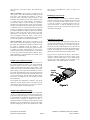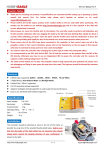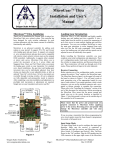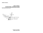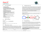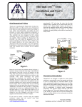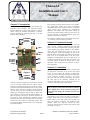
1
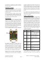
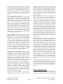
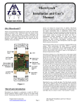
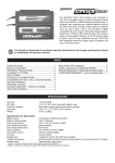
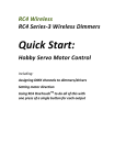
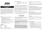
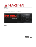
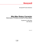
Channel-3 TM Installation and User’s Manual Channel-3™ Introduction Thank you for purchasing the Oregon Scale Aviation Inc. Channel-3TM servo controller. This solid state controller has been designed by scale aviation enthusiasts with the utmost concern for reliability and usability. Channel-3 performs automatically, permitting the pilot to do other tasks, like flying the plane! Each input has a buffered output, eliminating the need for “Y” connectors and each output is reversible. Ground Blk/Brn +5V Red/Red Signal Yel/Or Input 1 Channel-3™ Operation Example Input 2 Buffered Out 2 Buffered Out 1 Delay Pot Reverse Input Rev Output 1 Rev Output 2 Configure This controller can also be used as a delay or rate controller for a single input channel. It can create 2 completely independent delay or rate controllers based on two separate inputs. Output travel endpoints are independently adjustable. All endpoint and configuration settings are stored in non-volatile memory, making it a true “turn it on and fly” controller. No field adjustments or unique preflight stick movements are required Speed Pot Let’s say you want your plane’s canopy to open 15 seconds after you enter a landing configuration (gear and flaps down). This can be accomplished by connecting your radio receiver landing gear and flap channels to the controller inputs, and your sliding canopy servo to one of the controller outputs. Connect the Landing gear servos to the buffered output of the Landing Gear input and connect the Flap servos to the buffered output of the Flap input. Channel-3 will automatically open the cockpit canopy 15 seconds after the landing gear and flaps are lowered. The flap down position at which the canopy opens is fully adjustable. Other exciting uses of Channel-3 are left to your imagination. Channel-3™ Installation Output 2 Output 1 Figure 1 Signal Yel/Or +5V Red/Red Ground Blk/Brn Channel-3 operates an output servo based on the positions of up to two input channels from your radio’s receiver. Through user defined settings such as output servo delay, speed, and input channel threshold points, exciting control functions can be created. For example, you may decide to open the canopy in a slow and realistic manner when the landing gear are deployed and the flaps are below 80% down. Channel-3 can easily create this and in addition, can delay the opening of the canopy. The latest Channel-3 can now create 2 output channels with completely separate threshold points, travel rates and delays! The second output channel can even be made to continuously oscillate. This can be used to make a pilots hand wave or for cycling a gun turret back and forth! Oregon Scale Aviation Inc. Beaverton, Oregon 97007 Page 1 Before installing your Channel-3 controller, you must make the appropriate connections to the receiver and output servos. If you are using a JR, Airtronics or Futaba radio system, your servos will connect directly to the output pins of the Channel-3 controller (see Fig 1 for correct polarities). Note that all ground connections are towards the outer edge of the Channel-3 controller for all connectors. This makes it easy to quickly scan for correct connections before powering on the controller. WARNING! Please insure that the power and ground leads are properly connected to the Channel-3 controller before applying power to the system. Reversing power and ground may damage the controller and void your warranty Connections to your receiver can easily be made with a female to female cable. If you cannot purchase a female to female cable for your radio system, you can create one using the supplied connectors and standard aileron extender cables. This approach removes the male connectors from the aileron extenders and replaces them with female connectors. Channel-3 Installation and User’s Manual Doc # 1004106 For instructions on attaching the included connectors, please refer to the “Installing the Connectors” section at the end of this document. Installation and Setup Using female to female connectors, connect the receiver outputs for the radio channels you want to use to the Input 1 and Input 2 connectors (see Fig.1) on the Channel-3 controller. If you plan to use only a single input, it must be connected to Input 1. Before using the Channel-3 controller, you must complete some initial configuration settings and adjustments. There are 3 configuration modes. Each mode is entered by setting the switches to a unique position, and then powering on the unit. Perform all steps in the order indicated. Input Setup Mode The Input Setup Mode is used to configure the input signal direction. The controller can accommodate reversed outputs from your transmitter, but you must configure the controller for this reversing. Make sure the receiver is connected to the Channel-3 controller and that the receiver is off. If you will use two input channels (i.e. landing gear and flaps) make sure both are connected to the controller. Move Switch 4 (Configure) and Switch 3 (Rev Output 2) to the “On” position. Plug the supplied LED module into the Buffered Out 1 connector as shown in Figure 2. No servos should be plugged in at this time. Turn on the receiver and transmitter, and wait at least 15 seconds for you have the Landing Gear connected to Input 2, move the transmitter landing gear knob, lever or switch to the position that fully lowers the gear. If the input is configured correctly, the LED will flash. If it does not flash, change the position of Switch 1 (Reverse Input). Once the LED is flashing, move Switch 4 (Configure) to the “Off” position and turn off the receiver. Return all switches to the “Off” position. This completes the Input Setup Mode programming. The setup values are stored in permanent memory, and this step will not need to be repeated unless you reverse these channels on the transmitter. Output 1 Configuration Mode Output 1 Configuration mode is used to set all thresholds, travel limits and input conditions for Output 1. The following table indicates the sequence of the settings and LED flashes that occur while setting a threshold, limit or input condition. Once in the Output 1 Configuration mode, all settings must be completed in the order indicated in the table, and all settings must be finished in order for the settings to be stored in memory. If you turn off the controller anytime during the sequence, none of the settings will be stored in memory. If at anytime during the Output 1 or Output 2 Configuration Mode, the LED blinks 10 times rapidly, pauses and then repeats, it indicates that an upper travel limit has been set that is lower than the lower travel limit. If this occurs, power down the controller and carefully repeat the Input Setup Mode and Output 1 Configuration programming. LED Flashes 1 LED Module 2 3 4 Figure 2 the transmitter and receiver to link-up. Move the transmitter control for Input 1 to the “Down” position. For example, if you have the flaps connected to Input 1, move the transmitter flap knob, lever or switch to the position that fully lowers the flaps. If the input is configured correctly, the LED will flash. If it does not flash, move Switch 1 (Reverse (Input) to the “On” position. Once the LED is flashing, move Switch 4 (Configure) to the “Off” position. Input 1 is now configured for correct polarity. Repeat the process for Input 2 by moving Switch 4 (Configure) to the “On” position. Move the transmitter control for Input 2 to the “Down” position. For example, if Oregon Scale Aviation Inc. Beaverton, Oregon 97007 Page 2 5 6 Function Input 1 Qualified Above or Below Input 2 Qualified Above or Below Output 1 Upper Travel Limit Output 1 Lower Travel Limit Input 1 Threshold Input 2 Threshold Comments Determines if Input 1 must be above or below threshold in order to qualify Output 1 and start output 1 movement. Determines if Input 2 must be above or below threshold in order to qualify Output 1 and start Output 1 movement. Sets upper travel limit for Output 1. Sets lower travel limit for Output 1. Sets Input 1 position at which Output 1 is qualified and will start moving. Sets Input 2 position at which Output 1 is qualified and will start moving. To enter Output 1 Configuration Mode, turn off the receiver/controller and move both Switch 4 (Configure) and Switch 2 (Rev Output 1) to the “On” position. All Channel-3 Installation and User’s Manual Doc # 1004106 other switches must be in the “Off” position. Insure that the receiver is still connected to the Channel-3 controller and that the LED module is plugged into the Buffered Out 1 connector as shown in Fig 2. Plug the Output 1 servo into the Output 1 connector (see Fig 1) insuring correct polarity. Turn on the transmitter and the receiver and wait approximately 15 seconds for receiver and transmitter to link-up. Input 1 Qualified Above or Below: You will notice that the LED flashes once and then pauses. This indicates that Channel-3 is ready to accept the “Input 1 Qualified Above or Below” setting. For example, if you want the canopy to open when the Flaps are below 75% down, and flaps are on Input 1, then you would select “Below”. The “Below” name refers to any flap position physically below 75% down. If you wanted Output 1 to activate when the throttle was above 50%, and throttle was connected to Input 1, then you would select “Above”. Move switch 1 to the “On” position if you want an “Above” setting for Input 1. Move switch 1 to the “Off” position if you want a “Below” setting for Input 1. Now move Switch 4 (Configure) to the “Off” position. A switch is “Off” when it is moved towards the outer edge of the controller board. Input 2 Qualified Above or Below: Move Switch 4 (Configure) to the “On” position. You will notice that the LED flashes twice and then pauses. This indicates that Channel-3 is ready to accept the “Input 2 Qualified Above or Below” setting. Move Switch 1 to the “On” position if you want an “Above” setting for Input 2. Move Switch 1 to the “Off” position if you want a “Below” setting for Input 2. If you want Channel-3 to be a simple delay or rate controller for Input 1, and do not want Input 2 to interact with output 1, you can exclude input 2 by simply setting it to “Above”, and then setting its’ threshold to a value below its normal travel range. In this way, Input 2 is always “Above” its’ threshold. Now move Switch 4 (Configure) to the “Off” position. The LED will stop flashing. Output 1 Upper Travel Limit: Move Switch 4 (Configure) to the “On” position. You will notice that the LED flashes three times and then pauses. This indicates that Channel-3 is ready to accept the “Output 1 Upper Travel Limit” setting. The Output 1 servo can now be controlled by the channel connected to Input 1. Move the transmitter stick or knob/lever for Input 1 to the “up” position and observe the direction that Output 1 travels. If it travels in the wrong direction, reverse Output 1 by moving Switch 2 to the “On” position. Adjust Input 1 on the transmitter until Output 1 is in the desired full Up position. This for example would be the canopy closed position. As a reminder, Output 1 goes to its’ down position when both Input 1 and Input 2 meet the qualifying conditions (i.e. Flaps below 75% down and Landing Gear below 50% down). Once you are satisfied with the Output 1 upper travel limit position, move Switch 4 to the “Off” position. The LED will stop flashing. Output 1 Lower Travel Limit: Move Switch 4 (Configure) to the “On” position. You will notice that the Oregon Scale Aviation Inc. Beaverton, Oregon 97007 Page 3 LED flashes four times and then pauses. This indicates that Channel-3 is ready to accept the “Output 1 Lower Travel Limit” setting. Move the transmitter stick or knob/lever for Input 1 until Output 1 is in the desired full down position. This for example would be the canopy open position. Once you are satisfied with the Output 1 lower travel limit position, move Switch 4 to the “Off” position. The LED will stop flashing. Input 1 Threshold: Move Switch 4 (Configure) to the “On” position. You will notice that the LED flashes five times and then pauses. This indicates that Channel-3 is ready to accept the “Input 1 Threshold” setting. This threshold is the transmitter stick or knob position for Input 1 at which you want to activate Output 1. For example, if you want the canopy to open when flaps are 75% down (and flaps are connected to Input 1) then you will program the Input 1 threshold for the 75% flap position. If you have a switch connected to Input 1 (ie landing gear switch), then move the switch to the full down position and use the travel limit adjustment on the transmitter to nudge this input a little bit away from the 100% travel point for the switch (75% travel adjustment is a safe position). This will insure that noise wont accidentally activate the output. Once you are satisfied with the Input 1 Threshold position, move Switch 4 to the “Off” position. The LED will stop flashing. Be sure to reset your flap travel limit on the Tx to its original setting. Input 2 Threshold: Move Switch 4 (Configure) to the “On” position. You will notice that the LED flashes six times and then pauses. This indicates that Channel-3 is ready to accept the “Input 2 Threshold” setting. This threshold is the transmitter stick or knob position for input 2 at which you want to activate Output 1. For example, if you want the canopy to open when the Throttle is at 15% (and the throttle is connected to Input 2) then you will program the Input 2 threshold for the 15% throttle position. If you have a transmitter switch for Input 2 (ie landing gear switch), then use the transmitter travel limit adjustment to nudge this input a little bit away from the 100% travel point for the switch (75% travel adjustment is a safe position). This will insure that noise won’t accidentally activate the output. Once you are satisfied with the Input 2 Threshold position, move Switch 4 to the “Off” position. The LED will stop flashing. If you made adjustments to your transmitter travel limits, return them to their original settings. This completes the configuration of Output 1. If you intend to configure Output 2 at this time, then note the position of the Output 1 Reversing switch, and return all switches to the “Off” position. If you are not going to configure Output 2, then proceed to the “Output 1 Speed and Delay Settings” section. Output 2 Configuration Mode Output 2 Configuration Mode is used to set all thresholds, travel limits and input conditions for Output 2. The following table indicates the sequence of the settings and Channel-3 Installation and User’s Manual Doc # 1004106 LED flashes that occur while setting a threshold, limit or input condition. Once in the Output 2 Configuration mode, all settings must be completed in the order indicated in the table, and all settings must be finished in order for the settings to be stored in memory. If you turn off the controller anytime during the sequence, none of the settings will be stored in memory. If at anytime during the Output 2 Configuration Mode, the LED blinks 10 times rapidly, pauses and then repeats, it indicates an upper travel limit has been set that is lower than the lower travel limit. If this occurs, power down the controller and repeat the Input Setup Mode and Output 2 Configuration programming. LED Flashes 1 2 3 1 2 3 Function Input 1 Qualified Above or Below Input 2 Qualified Above or Below Output 2 Continuous Cycle Output 2 Upper Travel Limit Output 2 Lower Travel Limit Input 1 Threshold 4 Input 2 Threshold 5 Output 2 Speed and Delay Comments Determines if Input 1 must be above or below threshold in order to qualify Output and start Output 1 movement. Determines if Input 2 must be above or below threshold in order to qualify Output 1 and start Output 1 movement. If set, output 2 will continuously cycle back and forth until an input is disqualified Sets upper travel limit for Output 2. Sets lower travel limit for Output 2. Sets Input 1 position at which Output 2 is qualified and will start moving. Sets Input 2 position at which Output 2 is qualified and will start moving. Stores Output 2 Speed and Delay settings in memory. To enter Output 2 Configuration Mode, turn off the receiver and controller and move Switch 4 (Configure) to the “On” position. All other switches should be in the “Off” position. Insure that the receiver is still connected to the Channel-3 controller and that the LED module is plugged into the Buffered Out 1 connector as shown in Fig 2. Plug the Output 2 servo into the Output 2 connector (see Fig 1) insuring correct polarity. Remove the Output 1 servo from the Output 1 connector if it is installed. Turn on the transmitter and the receiver and wait approximately 15 seconds for receiver and transmitter to link-up. Oregon Scale Aviation Inc. Beaverton, Oregon 97007 Page 4 Input 1 Qualified Above or Below: You will notice that the LED flashes once and then pauses. This indicates that Channel-3 is ready to accept the “Input 1 Qualified Above or Below” setting for Output 2. Move switch 1 to the “On” position if you want an “Above” setting for Input 1. Move switch 1 to the “Off” position if you want a “Below” setting for Input 1. Now move Switch 4 (Configure) to the “Off” position. Note that “Off “ is toward the outer edge of the controller board. The LED will stop flashing. Input 2 Qualified Above or Below: Move Switch 4 (Configure) to the “On” position. You will notice that the LED flashes twice and then pauses. This indicates that Channel-3 is ready to accept the “Input 2 Qualified Above or Below” setting for Output 2. Move Switch 1 to the “On” position if you want an “Above” setting for Input 2. Move Switch 1 to the “Off” position if you want a “Below” setting for Input 2. Now move Switch 4 (Configure) to the “Off” position. The LED will stop flashing. Output 2 Continuous Cycle: Move Switch 4 (Configure) to the “On” position. The LED will flashes three times, pause and then repeat. This indicates that Channel-3 is ready to accept the “Output 2 Continuous Cycle” setting. Continuous cycling will cause Output 2 to travel from one endpoint limit to the other endpoint limit continuously until an input moves to a disqualified position. This can be used to rotate a turret back and forth, create a bomb release ratchet, or even make a pilot wave his arm! Move Switch 1 to the “On” position if you want to enable continuous cycling, otherwise leave it in the “Off” position. Now move Switch 4 (Configure) to the “Off” position. The LED will stop flashing. Output 2 Upper Travel Limit: Move Switch 4 (Configure) to the “On” position. You will notice that the LED flashes once and then pauses. This indicates that Channel-3 is ready to accept the “Output 2 Upper Travel Limit” setting. The Output 2 servo can now be controlled by Input 1. Move the transmitter stick or knob/lever for Input 1 to the up position. Output 2 should move in the direction desired for an “Up” output. If it does not, reverse Output 2 by moving Switch 3 to the “On” position. Now make fine adjustments of the transmitter until Output 2 is in the desired full up position. This, for example, would be the canopy closed position. As a reminder, Output 2 goes to its’ down position when both Input 1 and Input 2 meet the qualifying conditions (ie Flaps below 75% down and Landing Gear below 50% down). Once you are satisfied with the Output 2 upper travel limit position, move Switch 4 to the “Off” position. The LED will stop flashing. Output 2 Lower Travel Limit: Move Switch 4 (Configure) to the “On” position. The LED will flash twice, pause and then repeat. This indicates that Channel-3 is ready to accept the “Output 2 Lower Travel Limit” setting. Move the transmitter stick or knob/lever for Input 1 until Output 2 is in the desired full down position. Once you are satisfied with the Output 2 lower travel limit position, Channel-3 Installation and User’s Manual Doc # 1004106 move Switch 4 to the “Off” position. The LED will stop flashing. Input 1 Threshold: Move Switch 4 (Configure) to the “On” position. The LED will flash three times, pause and then repeat.. This indicates that Channel-3 is ready to accept the “Input 1 Threshold” setting for Output 2. This threshold is the transmitter stick or knob position for Input 1 at which you want to activate Output 2. For example, if you want the canopy to open when flaps are 75% down (and flaps are connected to Input 1) then you will program the Input 1 threshold for the 75% flap position. If you have a transmitter switch for controlling the channel connected to Input 1 (ie landing gear switch), then use the transmitter travel limit adjustment to nudge this input a little bit away from the 100% travel point for the switch (75% travel adjustment is a safe position). This will insure that noise won’t accidentally activate the output. Once you are satisfied with the Input 1 Threshold position, move Switch 4 to the “Off” position. The LED will stop flashing. Input 2 Threshold: Move Switch 4 (Configure) to the “On” position. The LED will flash four times, pause and then repeat. This indicates that Channel-3 is ready to accept the “Input 2 Threshold” setting for Output 2. This threshold is the transmitter stick or knob position for Input 2 at which you want to activate Output 2. Once you are satisfied with the Input 2 Threshold position, move Switch 4 to the “Off” position. The LED will stop flashing. If you made adjustments to your transmitter travel limits, return them to their original settings. Output 2 Speed and Delay Settings Since the pots on the Channel-3 controller are used to set the speed and delay for Output 1, the speed and delay values for Output 2 must be stored in memory. In the Output 2 Speed and Delay setting mode, Output 2 will continuously cycle back and forth, with delays at each end. While cycling, you can adjust the potentiometers to achieve the desired speed and delay settings. Turning the speed and delay pots clockwise increases the speed and delay. Once you have achieved the desired speed and delay values, move Switch 4 (configure) to the “Off” position. The LED will stop flashing. This completes the configuration of Output 2. Turn off the Channel-3 controller. Return Switch 1 and Switch 4 to the “Off” position and return Switch 2 to the correct position for reversing Output 1 that you noted earlier. take several activate/deactivate cycles to achieve the desired results Installing in Your Aircraft Wrap the Channel-3TM controller in vibration damping foam (the same kind used for mounting the receiver) and secure it in a convenient location in the aircraft. It is best to keep the controller a reasonable distance from the receiver and antenna. As with the installation of any new equipment in you aircraft, always perform a ground range check before initial flight. Installing the Connectors To attach your wiring to the supplied pins, simply strip the wire back approximately 1/8” and crimp the wire into the supplied pin using a crimping tool or needle nosed pliers. Be sure the wires are firmly crimped in place, and insert all 3 leads into the supplied housing until the retention fingers snap into the housing slot. Test your installation by gently pulling on the leads to insure they are firmly seated. Plug your receiver outputs into the “Input 1” and “Input 2” connectors, and the output servos into the “Output 1” and “Output 2” connectors (see Figure 1). If you need buffered versions of the input channels, they are available on the “Buffered Out 1” and “Buffered Out 2” connectors. Retention Slots Retention Finger Crimp Wire Figure 3 Output 1 Speed and Delay Settings Output 1 travel speed is controlled by the Travel Speed Pot (see Fig. 1). Turning this pot clockwise increases the travel speed. The activation of Output 1 can also be delayed by up to approximately 30 seconds after the qualifying conditions have been met by adjusting the Delay Pot (see Fig. 1). Turning the Delay Pot clockwise increases the delay. These adjustments can be accomplished by activating the output and then adjusting the pots for the desired result. It may Oregon Scale Aviation Inc. Beaverton, Oregon 97007 Page 5 Channel-3 Installation and User’s Manual Doc # 1004106 Channel-3™ Features Outputs activated based on positions of 2 input channels. Two separate output channels can be created Individually adjustable output delays (up to ~30 seconds) Individually adjustable output travel rates. Individually adjustable output travel limits All outputs reversible Buffered outputs eliminating need for “Y” connectors Can delay and/or slow 2 separate channels. Included LED module assists in configuration & setup. Designed and manufactured in the USA. Channel-3™ Specifications Voltage Range…………………………….. 4.5V – 8.5V Current Consumption……………< 10ma (4.5V – 5.5V) <15ma @ 7.0V Input Signal Swing......................... 2.0V Min, 5.3V Max Operating Temp………………………………0C - 70C Warranty OSA warrants the Channel-3TM controller to be free from defects in materials and workmanship for a period of 90 days from the date of purchase. If your controller is defective, return to OSA with proof of purchase and we will repair or replace the controller as deemed appropriate by OSA. This warranty does not include damage due to accidents, misuse, improper installation, tampering, radio interference, unauthorized repair or acts of God. OSA will not be responsible or pay for loss of time, loss of use, inconvenience, incidental, consequential or property damages due to the use of this product. Oregon Scale Aviation Inc. Beaverton, Oregon 97007 Page 6 Channel-3 Installation and User’s Manual Doc # 1004106