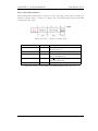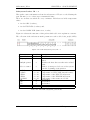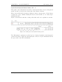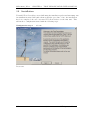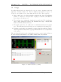
1
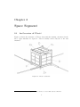
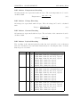
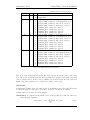
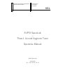
Scuola universitaria professionale
della Svizzera italiana
Dipartimento
Tecnologie
Innovative
SSL
SUPSI SpaceLab
–
TIsat-1 Ground Segment Team
Operative Manual
SUPSI SpaceLab
20.03.2010
(Doc. SSL-100320_DI-en)
Revisions
Rev.
0
1
1.1
Date
20.03.2010
12.05.2010
11.06.2010
Author
IBo
IBo/PCe
IBo/PCe
Date of printing: July 11, 2010
Description
First version.
Reviewed draft.
Production (launch time) version.
Contents
1 Introduction
5
2 Space Segment
2.1 An Overview of TIsat-1 . . . . . . . . . . . . .
2.2 COMM Subsystems Overview . . . . . . . . . .
2.2.1 Mission Sequence . . . . . . . . . . . . .
2.2.2 Post Separation Operation . . . . . . . .
2.2.3 Nominal RF Operating Scheme . . . . .
2.2.4 Operating sequences . . . . . . . . . . .
2.2.5 Beacon . . . . . . . . . . . . . . . . . .
2.2.6 Transceiver . . . . . . . . . . . . . . . .
2.3 Downlink . . . . . . . . . . . . . . . . . . . . .
2.3.1 Beacon CW Type of Modulation . . . .
2.3.2 Alinco Audio-Morse Type of Modulation
2.3.3 Alinco Audio-FSK Type of Modulation
2.3.4 Alinco Audio-PSK Type of Modulation
2.3.5 Beacon Packet Architecture . . . . . . .
2.3.6 Alinco Morse Packet Architecture . . . .
2.3.7 Alinco FSK Packet Architecture . . . .
2.3.8 Alinco PSK Packet Architecture . . . .
2.3.9 Beacon Packet Coding Details . . . . . .
2.3.10 Alinco Morse Coding Details . . . . . .
2.3.11 Alinco FSK Coding Details . . . . . . .
2.3.12 Alinco PSK Coding Details . . . . . . .
2.4 Uplink . . . . . . . . . . . . . . . . . . . . . . .
.
.
.
.
.
.
.
.
.
.
.
.
.
.
.
.
.
.
.
.
.
.
.
.
.
.
.
.
.
.
.
.
.
.
.
.
.
.
.
.
.
.
.
.
.
.
.
.
.
.
.
.
.
.
.
.
.
.
.
.
.
.
.
.
.
.
.
.
.
.
.
.
.
.
.
.
.
.
.
.
.
.
.
.
.
.
.
.
.
.
.
.
.
.
.
.
.
.
.
.
.
.
.
.
.
.
.
.
.
.
.
.
.
.
.
.
.
.
.
.
.
.
.
.
.
.
.
.
.
.
.
.
.
.
.
.
.
.
.
.
.
.
.
.
.
.
.
.
.
.
.
.
.
.
.
.
.
.
.
.
.
.
.
.
.
.
.
.
.
.
.
.
.
.
.
.
.
.
.
.
.
.
.
.
.
.
.
.
.
.
.
.
.
.
.
.
.
.
.
.
.
.
.
.
.
.
.
.
.
.
.
.
.
.
.
.
.
.
.
.
.
.
.
.
.
.
.
.
.
.
.
.
.
.
.
.
.
.
.
.
.
.
.
.
.
.
.
.
.
.
.
.
.
.
.
.
.
.
.
.
.
.
.
.
.
.
.
.
.
.
.
.
.
.
.
.
.
.
.
.
.
.
.
.
.
.
7
7
8
8
8
8
9
11
11
12
12
12
13
14
14
19
19
20
28
37
37
38
42
3 TIsat Demodulator User’s Manual
3.1 Basic Concepts . . . . . . . . . . . . . . .
3.1.1 Download . . . . . . . . . . . . . .
3.1.2 Soft- and Hardware Requirements
3.1.3 Workspace . . . . . . . . . . . . . .
3.1.4 Logs and Feedback . . . . . . . . .
3.2 Installation . . . . . . . . . . . . . . . . .
3.3 Usage . . . . . . . . . . . . . . . . . . . .
.
.
.
.
.
.
.
.
.
.
.
.
.
.
.
.
.
.
.
.
.
.
.
.
.
.
.
.
.
.
.
.
.
.
.
.
.
.
.
.
.
.
.
.
.
.
.
.
.
.
.
.
.
.
.
.
.
.
.
.
.
.
.
.
.
.
.
.
.
.
.
.
.
.
.
.
.
.
.
.
.
.
.
.
.
.
.
.
.
.
.
43
43
43
43
44
44
46
50
3
.
.
.
.
.
.
.
.
.
.
.
.
.
.
.
.
.
.
.
.
.
SSL-100320_DI-en
CONTENTS
Acronyms and Terms
AGC
CCR
DoL
ECC
EOC
EOD
EPS
OBC
OPR
GS
PV
RFPC
RX
TX
TU
CBD
WPM
SSL
Automatic Gain Control
Capture and Compare Registers [?]
Days of Life (in-orbit mission duration)
Error Correcting Code
End Of Charge (related to batteries)
End Of Discharge (related to batteries)
Electric Power Supply
On-Board Computer
Orbit PRofile (related to datasets in telemetry)
Ground Station
Photovoltaic
RF Power Checker
Receive or Receiver
Transmit or Transmitter
Timing Unit
CPU Boot Delay: the time between boot of the CPUs as assigned
by the TU.
Words per Minute, the Morse transmission rate measure.
4 / 50
GST Operative Manual
Chapter 1
Introduction
TIsat-1 is the first staff and student made satellite of SUPSI-SpaceLab.
For communication TIsat-1 relies on amateur radio frequencies which were coordinated with the International Amateur Radio Union (IARU).
This document describes
1. the radio communication system,
2. the modulation methods,
3. the communication frame architecture and
4. the frame details of TIsat-1.
This information will enable decoding of TIsat-1’s signals even without the specific
software that SUPSI-SpaceLab has prepared for the mission.
Further a short installation and user guide for the demodulation and decoding software
provided by SUPSI-SpaceLab is given.
5
SSL-100320_DI-en
SSL
CHAPTER 1. INTRODUCTION
6 / 50
GST Operative Manual
Chapter 2
Space Segment
2.1
An Overview of TIsat-1
Figure 2.1 shows the structure of TIsat-1 along with the naming convention for the
sides. Four antennas are depicted: TIsat-1 actually carries only two of the four
antennas1 .
Figure 2.1: TIsat-1: structure.
1
Emission efficiency was experimentally found to be better with only two antennas.
7
SSL-100320_DI-en
2.2
CHAPTER 2. SPACE SEGMENT
COMM Subsystems Overview
TIsat-1 carries two radio devices working in the UHF respectively in the VHF band. A
home grown beacon transmitter is dedicated to downlink short telemetry (i.e. essential
information) and operates in UHF (437.305 MHz) with CW modulation. The beacon
is also used as emergency radio and first communication device, just after the launch.
The second device is a commercial FM transceiver (Alinco) used for up- as well as for
down-link. It is adapted to handle several audio tone modulation schemes providing
an higher bit-rate than the beacon. This radio is used to transmit the full telemetry
in the VHF band (145.980 MHz). The two radios relay each other during TIsat-1’s
mission with a time-slice logic.
2.2.1
Mission Sequence
The four stage PSLV rocket is expected to cut-off thrust of PS4 (fourth stage) at
liftoff +1034.2s. This time is called T6.
TIsat-1 will separate from the Launch Vehicle (LV) at T 6 + 135.4s. Up to separation
time the spacecraft is powered off.
2.2.2
Post Separation Operation
After separation, i.e. the spacecraft leaves the XPOD, complying with the CDS2
rev. 11, TIsat-1 will
1. wait for at least 900s before deploying antennas. While waiting, TIsat-1 will
sample the internal temperature and will activate the deployment system only
if the temperature is above 0o C, but not later than 130 min after separation.
No communication will take place during this time.
2. After antenna deployment, for the next 900s, short beacon transmission are
allowed. The Morse string "tisat1 hb9de" is transmitted.
3. After 1800s (30 min) nominal spacecraft operation is entered.
2.2.3
Nominal RF Operating Scheme
The two downlink devices (Beacon and FM transceiver) alternate each orbit. During
even orbits the beacon is used, while the FM transceiver is used during the next (odd)
orbit.
During the FM transceiver orbit, a data packet transmission is repeated for 25 seconds
each minute, queuing 4 PSK packets with 1 FSK packet. Find additional information
on packet encoding and transmission in the next sections.
The beacon transmission rate is toggled from slow (16 WPM) to fast-rate (100 WPM)
every 32 orbits.
2
CubeSat Design Specification.
SSL
8 / 50
GST Operative Manual
CHAPTER 2. SPACE SEGMENT
2.2.4
SSL-100320_DI-en
Operating sequences
COMM operating sequences are tied to the Operating Modes and Operating Cycles of
the spacecraft.
The spacecraft Operating Modes
TIsat-1 is programmed to periodically execute three basic operations during its nominal life:
1. perform housekeeping measurements and procedures and payload tests;
2. transmit data to the Ground Stations;
3. receive commands.
The firmware of the OBC is able to self configure the satellite depending on which
operation has to be executed. A fixed timeslot is allotted to each operation; when the
slot times out the current operation is terminated and the next is started.
The software and hardware configuration related to each operation is called Operating
Mode.
There are five Operating Modes:
n.
1
2
3
4
5
Operating Mode
Housekeeping
Transmission with FM radio
Transmission with beacon
Reception
Sleep
Timeslot (s)
15
25
25
20
25
Notes
TX_FM mode
TX_Beacon mode
RX mode
Houskeeping mode: the CPU basically reads the sensors and stores the results
in memory. This operating mode takes 15 seconds. No radio transmission is
activated during this time.
When the housekeeping time expires, TIsat-1 enters one of two transmission
modes, unless energy saving is necessary, in which case the satellite enters Sleep
mode.
TX_FM mode: this mode is entered during even numbered orbits and lasts 25
seconds. The satellite uses the FM radio going through its modulations schemes
and packets: four operating cycles with PSK and one with AM-FSK packets.
The same packet is repeated so many times as needed to fill the 25 seconds of
the TX mode. After that the RX mode is activated.
TX_Beacon mode: this mode is entered during odd numbered orbits and lasts 25
seconds. The satellite uses the beacon (CW) to send the specific packets at two
different data rates.
Slow rate: the transmission scheme is periodic in five steps
1. transmission of the callsign;
2. Beacon short packet type 1;
GST Operative Manual
9 / 50
SSL
SSL-100320_DI-en
CHAPTER 2. SPACE SEGMENT
3. Beacon short packet type 2;
4. Beacon short packet type 3;
5. Beacon short packet3 type 4.
The packets are repeated to fill the 25 seconds of the mode timeslot.
Fast rate: the Beacon ”Complete packet” described in section 2.3.5 is repeated
over and over during the 25 seconds of the mode timeslot.
After that the Rx mode is activated.
Sleep mode: in this mode no activity occurs for 25 seconds. This is the power saving
mode. It is activated either in eclipse, in case of emergency and over equatorial
latitudes, where the satellite has the maximum exposition of the solar panels.
RX mode: the FM transceiver is turned on in receive mode and the satellite waits
for commands from the Ground Stations. If no command is received within 20
seconds, the mode is terminated, otherwise the satellite keeps in RX mode until
a "End of RX" command is received or the processor timeslot (max 5 minutes)
expires.
The RX mode is the only mandatory mode for each cycle; its duration is at
least 20s every 40s.
The spacecraft Operating Cycles
A sequence of three operating modes, that matches the basic operations of the satellite, is called a Operating Cycle.
Each Operating Cycle takes one minute to execute.
Figure 2.2: Operating modes (bubbles) and cycles (closed paths) of TIsat-1.
Note (fig. 2.2) that any closed path following the oriented edges of the graph represents
one possible Operating Cycle and takes 1 minute to execute.
3
Beacon Packets are described in section 2.3.5.
SSL
10 / 50
GST Operative Manual
CHAPTER 2. SPACE SEGMENT
SSL-100320_DI-en
The scheduling and execution sequence of the operating modes depends on specific
real time constraints. Decisions are based on energy availability, sunlight conditions4 ,
temperature, estimated position along the orbit, etc.
Depending on the situation, there can be cycles without TX state.
The Processor Timeslot
For redundancy purposes, the OBC of TIsat-1 is built with two independent microcontrollers relaying each other periodically in control of the spacecraft.
The time allotted to each processor is called Processor Timeslot and, for TIsat-1, it
is set to 5 minutes.
During the timeslot the processor executes 5 Operating Cycles.
The two microcontrollers are programmed to be functionally identical, so they behave
the same way during each one’s timeslot.
2.2.5
Beacon
The beacon transmitter is tuned to the RF frequency of 437.305MHz.
The output of the transmitter is switched on and off to achieve information transport.
This procedure is commonly referred to as CW (Continuous Wave) or OOK (On-OffKeying) modulation.
2.2.6
Transceiver
The transceiver used on TIsat-1 is a FM device. Its carrier frequency is set to
145.980MHz according to the IARU coordinated frequency for the spacecraft and
is modulated by audio tones injected via the microphone jack.
The term modulation used in the following always refers to audio types of modulation.
All types of modulation for the transceiver have been implemented in software and
are part of the experimental payload for TIsat-1. The audio tones are generated by
the OBC.
4
During eclipse the batteries cannot be recharged, therefore the power consumption shall be
limited.
GST Operative Manual
11 / 50
SSL
SSL-100320_DI-en
2.3
2.3.1
CHAPTER 2. SPACE SEGMENT
Downlink
Beacon CW Type of Modulation
The transmission method is based on Morse encoding.
The data rates are the same as for the FM transceiver, i.e. 16 WPM at slow rate and
100 WPM at fast rate.
2.3.2
Alinco Audio-Morse Type of Modulation
A 880Hz tone of changing duration, interleaved with silence is synthesized by the
OBC of TIsat-1 (fig. 2.3) and is injected to the microphone input of the transceiver.
Figure 2.3: The Morse modulation.
The symbols dot (dit) and dash (dah) are coded with a short / long sound preceded
and followed by silence. Silences have different durations depending on their position:
inter-symbol, inter-character of the same word, inter-word.
The duration for symbols and silences in the scheme adopted for TIsat-1 is reported
in table 2.1 (1:2:5 scheme).
Object
Dot (dit)
Dash (dah)
Inter-symbol silence
Inter-character silence
Inter-words silence
Duration
base unit
3 dots
1 dot
2 dots
5 dots
Table 2.1: Morse symbol duration
The Morse data rate is expressed in Words Per Minute (WPM), where the reference
word is ”PARIS”.
Table 2.2 shows the enconding for the standard word.
P
· − −·
A
·−
2
R
·−·
2
I
··
2
S
···
2
5
Table 2.2: Morse encoding of standard word "PARIS".
The duration of a dot in seconds can be computed as follows.
The word "PARIS" contains 10 dots, 4 dashes, 9 inter-symbol silences, 4 intercharacter silences and 1 inter-word silence, which is equivalent to
(10 · 1) + (4 · 3) + (9 · 1) + (4 · 2) + (1 · 5) = 44 dots.
SSL
12 / 50
(2.1)
GST Operative Manual
CHAPTER 2. SPACE SEGMENT
SSL-100320_DI-en
Defining this value as dots-per-word (dpw), one can compute the time per dot as in
equation 2.2.
60s
T imeP erDot =
(2.2)
W P M · dpw
The Audio-Morse type of modulation for TIsat-1 runs at 16 WPM at slow rate and
100 WPM at fast rate. Dot time for these rates is summarized in table 2.3.
Data Rate (WPM)
16
100
Dot time(ms)
85.2
13.6
Table 2.3: Dot time
Morse modulation with the FM transceiver has modest throughput compared to the
other modulation schemes.
2.3.3
Alinco Audio-FSK Type of Modulation
The two logic symbols ’0’ and ’1’ are mapped to the audio tones, 1200Hz and 600Hz.
The amplitude of the two tones is different and is tuned to favour the decoding process.
The digital raw data is Differential-Manchester encoded prior to modulation.
The chosen encoding scheme (fig. 2.4)5 calls for a change at the beginning of each bit
cell (regardeless of the data value) and further:
Data Value
’1’
’0’
Center of Bit-Cell
No change
Change occurs
Figure 2.4: The FSK modulation with Manchester data enconding
With this modulation TIsat-1 acheives a bit rate BR ≈ 100 bit/s.
The minimum and maximum number of uninterrupted full tone periods can be calculated as follows:
Nmin =
NM AX
5
=
1
BR
1
BR
·
1
· ftone
2
· ftone = 2 · Nmin
(2.3)
(2.4)
Documented as Biphase Mark Code in WikiPedia.
GST Operative Manual
13 / 50
SSL
SSL-100320_DI-en
CHAPTER 2. SPACE SEGMENT
Nmin numerical values:
Nmin_600Hz =
Nmin_1200Hz =
2.3.4
1
100
1
100
1
· 600 = 3
2
1
· · 1200 = 6
2
·
Alinco Audio-PSK Type of Modulation
A tone of 1400Hz is the basis for the PSK modulation. One period of the tone
1
(T = 1400Hz
≈ 714 µs) represents one bit of data.
At the occurrence of each data bit of value ’1’, the phase of the tone is reversed
(shifted by 180◦ ), otherwise no phase shift is introduced (fig. 2.5). This is actually
Differential Phase Shift Keying modulation (DPSK).
Figure 2.5: The PSK Modulation (DPSK)
With this modulation TIsat-1 acheives a bit rate BR ≈ 1400 bit/s.
PSK is used to download the complete telemetry of TIsat-1.
2.3.5
Beacon Packet Architecture
The Beacon of TIsat-1 sends a set of instantaneous parameter values using Morse
code. In order to make data packets as short as possible the encoding scheme of
table 2.4 for every nibble of data6 was chosen.
The 16 shortest Morse characters were mapped to the 16 hexadecimal values (0x0
. . . 0xF) possible with 4 bits, i.e. a nibble.
For TIsat-1 this is referred to as Morse short-form.
Packets
The beacon sends six different packets of data.
n.
Packet Name
1
Callsign
2
3
4
5
6
Battery status
Subsystems status
Photovoltaic temperature
Payload
Complete
Data Rate
(WPM)
16
16
16
16
16
100
Comment
Contains HB9DE in plain Morse
(no Short-form encoding).
Collects all the above information
6
The term nibble is largely used to define different quantities of bits. For this document a nibble
is 4 bits. Two concatenated nibbles generate a byte (8 bits).
SSL
14 / 50
GST Operative Manual
CHAPTER 2. SPACE SEGMENT
Nibble Value
0x0
0x1
0x2
0x3
0x4
0x5
0x6
0x7
0x8
0x9
0xA
0xB
0xC
0xD
0xE
0xF
SSL-100320_DI-en
Character
E
I
T
N
S
A
H
D
R
M
K
U
B
5
F
L
Morse Code
·
··
−
−·
···
·−
· · ··
−··
·−·
−−
−·−
··−
− · ··
·····
· · −·
· − ··
Length (dots)
1
3
3
5
5
5
7
7
7
7
9
7
9
9
9
9
Table 2.4: Morse short format encoding for TIsat-1
The beacon is thought to be easily heard and understood by anyone with knowledge of
the Morse code. Any standard Morse decoding software can be used to automatically
put the dit-dah into text. Decoding can be acheived even by hand, following the rules
listed in the next sections.
SUPSI-SpaceLab provides software to automatically gather, check, save and decode
data from TIsat-1.
Battery status packet
The battery status packet shows the actual temperature and voltage of the two batteries of TIsat-1: a Lithium-Polimer (LiPo, 1400 mAh, 4V, nominal 3.6V) and a
Lithium-Ion (LiIon, 2400 mAh, 4V, nominal 3.6 V).
The structure of the packet is shown in figure 2.6. Each square (numbered 1 . . . 12)
is one of Short-form Morse charactes encoding a 4 bit value (see table 2.4). The first
box (Sync) on the left is the synchronization symbol (a non standard Morse symbol).
Refer to table 2.5 for decoding.
Figure 2.6: Beacon battery status packet
GST Operative Manual
15 / 50
SSL
SSL-100320_DI-en
CHAPTER 2. SPACE SEGMENT
Character
1
2-4
5
6-7
8-9
10
11
12-13
Name
Packet ID and processor ID
Orbit number
Approximate latitude
Lithium-Polymer Temperature
Lithium-Ion Temperature
Lithium-Polymer Voltage
Lithium-Ion Voltage
Checksum
Table 2.5: Battery status packet fields.
Subsystems status packet
Figure 2.7, and table 2.6 summarize the structure of the packet and the information
of each field.
Figure 2.7: Beacon Subsystems status packet
Character
1
2-4
5
6-7
8-9
10-11
12-13
Name
Packet ID and processor ID
Orbit number
Approximate latitude
Alinco temperature
Beacon temperature
OBC temperature
Checksum
Table 2.6: Subsystems status packet fields
Photovoltaic temperature packet
Each of the 6 photovoltaic modules of TIsat-1 is monitored by a thermometer. The
temperature of the sides X-, Y+ and Z- are available in this packet.
The structure of the packet is shown in figure 2.8.
Refer to table 2.7 for decoding.
SSL
16 / 50
GST Operative Manual
CHAPTER 2. SPACE SEGMENT
SSL-100320_DI-en
Figure 2.8: Beacon Photovoltaic temperatures packet.
Character
1
2-4
5
6-7
8-9
10-11
12-13
Name
Packet ID and processor ID
Orbit number
Approximate latitude
X- side temperature
Y+ side temperature
Z- side temperature
Checksum
Table 2.7: Photovoltaic temperature packet fields
Payload packet
On each side of TIsat-1, eight thin wire probes are exposed to the environment and
are continously monitored to verify their degradation (break/no break) during time
in space. The purpose of the test is to measure how long these wires survive in the
Low Earth Orbit environment, in particular related to the effect of atomic oxygen.
This is part of the experimental payload and is referred to as ”the material payload”
in this document.
The status of four wires per side is available in the beacon payload packet, taking
up 6 nibbles (fig. 2.9, M1 . . . M6). A bit value of ’0’ in these nibbles means ”wire
interrupted”.
The issue of the test of an electromechanical device (microrelais) is available in character n. 12.
The structure of the packet is shown in figure 2.9.
Refer to table 2.8 for decoding.
Figure 2.9: Beacon payload packet.
GST Operative Manual
17 / 50
SSL
SSL-100320_DI-en
CHAPTER 2. SPACE SEGMENT
Character
1
2-4
5
6-11
12
13-14
Name
Packet ID and processor ID
Orbit number
Approximative latitude
Material payload
Relais payload
Checksum
Table 2.8: Payload packet fields
Complete packet
A longer packet, called Complete packet, merges the information of the four shorter
beacon packet discussed in the previous sections. The data rate for the Complete
packet is 100 WPM.
Field verification of communication reliability with packets of different length is one
issue of interest for the TIsat-1 mission.
The structure of the packet is shown in figure 2.10.
Refer to table 2.9 for decoding.
Figure 2.10: Beacon complete packet.
SSL
18 / 50
GST Operative Manual
CHAPTER 2. SPACE SEGMENT
Character
1
2-4
5
6-7
8-9
10
11
12-13
14-15
16-17
18-19
20-21
22-23
24-29
30
31-32
SSL-100320_DI-en
Name
Packet ID and processor ID
Orbit number
Approximate latitude
Lithium-Polymer battery temperature
Lithium-Ion battery temperature
Lithium-Polymer battery voltage level
Lithium-Ion battery voltage level
Alinco temperature
Beacon temperature
OBC temperature
X- side temperature
Y+ side temperature
Z- side temperature
Material payload
Relais payload
Checksum
Table 2.9: Complete packet fields
2.3.6
Alinco Morse Packet Architecture
See section 2.3.5.
2.3.7
Alinco FSK Packet Architecture
The AM-FSK modulation is used to send a single packet of telemetry.
The data is represented in a single string of ASCII characters (letters, numbers, spaces
and points) as in table 2.10.
The resulting string should appear as in figure 2.11. Negative values are appended in
the string without space, beginning with their minus sign.
23.4 4.000 1.200 24.4 4.000 1.000 24.7 25.7 23.5 24.0 25.0 24.5 32.1-0.8 24.0-3.0 20.0-1.6
Figure 2.11: Example of Alinco FSK data string
GST Operative Manual
19 / 50
SSL
SSL-100320_DI-en
Position
1
2
3
4
5
6
7
8
9
10
11
12
13
14
15
16
17
18
CHAPTER 2. SPACE SEGMENT
Description
Lithium-ion battery temperature
Lithium-ion battery voltage
Lithium-ion current
Lithium-polymer temperature
Lithium-polymer voltage
Lithium-polymer current
FM radio board temperature
CW radio board temperature
EPS 1 board temperature
EPS 2 board temperature
OBC board temperature 1
OBC board temperature 2
PV generator side X- temperature
PV generator side Y+ temperature
PV generator side Z+ temperature
PV generator side X+ temperature
PV generator side Y- temperature
PV generator side Z- temperature
Unit
oC
V
A
oC
V
A
oC
oC
oC
oC
oC
oC
oC
oC
oC
oC
oC
oC
Format
± xx.x
x.xxx
± x.xxx
± xx.x
x.xxx
± x.xxx
± xx.x
± xx.x
± xx.x
± xx.x
± xx.x
± xx.x
± xx.x
± xx.x
± xx.x
± xx.x
± xx.x
± xx.x
Table 2.10: Alinco FSK Packet Architecture
2.3.8
Alinco PSK Packet Architecture
For TIsat-1 the PSK modulation offers the highest bit rate. PSK is therefore used to
send the full telemetry and the ”orbit profiles”, i.e. data collected and stored during
the whole orbit.
Four PSK packets have been foreseen. Each of them contains one or more complete
profile with a selection of different parameters.
The four PSK packets are transmitted sequentially and transmission is repeated over
and over during the dedicated time-slice of TIsat-1.
Integrity of the data can be checked and some correction can be applied at the receiving end thank to a Golay(12,24) error detection and correction (EDAC) scheme
implemented on TIsat-1.
Decoding of the PSK packets can be achieved even disregarding the EDAC scheme.
In the next sections the PSK packets will therefore be presented first ignoring the
EDAC check bits.
An explanation of how to deal with and take advantage of the EDAC bits will be
given in section 2.3.8.
Figure 2.12: Structure of PSK packets
The header is followed by the orbit profiles, depending on packet ID.
SSL
20 / 50
GST Operative Manual
CHAPTER 2. SPACE SEGMENT
SSL-100320_DI-en
Sync and Packet Header
Each PSK packet starts with a sequence of ones (11 bits), called Sync, followed by
what we call the header (3 bytes), see figure 2.13. The PSK packet carries from 200
to 400 bytes (fig. 2.12).
Figure 2.13: Sync + Header of PSK packets
Name
Sync
Size (bit)
11
Packet ID
Orbit number
8
12
Approximate latitude
4
35
Description
To synchronize detection of the packets.
Eleven bit at ’1’.
Identifier.
Total number of orbits completed at the
time of transmission.
1
In ( 16
· 360o ) starting from the terminator at orbit time.
Total (bit)
Table 2.11: Sync + header fields of the PSK packets (refer to fig. 2.13)
GST Operative Manual
21 / 50
SSL
SSL-100320_DI-en
CHAPTER 2. SPACE SEGMENT
Subsystems Packet: ID = 1
This packet carries information about the subsystems of TIsat-1 recorded during the
past 150 min (ca. 1.5 orbits) up to transmission time.
There are 30 data sets taken one every 5 minutes. Each data set holds temperature
values
1. for the OBC (2 values),
2. for the EPS PCBs (2 values) and
3. for the COMM PCB (transceiver, 1 value)
Figure 2.14 shows the structure of this packet while table 2.12 explains its contents.
The collection of the 30 datasets with 5 parameters each is called orbit profile (OPR).
Figure 2.14: PSK subsystem packet, ID = 1
Name
Sync - Header
Eclipse pointer
Size (bit)
35
8
Sunlight pointer
8
Reboot counter
8
ϑ OBC1
ϑ OBC2
ϑ EPS1
ϑ EPS2
ϑ COMM
CS1
CS2
CS3
× 30
× 30
× 30
× 30
× 30
8
8
8
1283
8
8
8
8
8
Description
See table 2.11
Identifies the first data set taken after orbital
sunset.
Identifies the first data set taken after orbital
dawn.
Number of unexpected reboots of the system
from the beginning of the mission.
Temperature of OBC (PCB sensor).
Temperature of CPU1 (MSP internal sensor).
Temperature of the EPS-TU subsystem.
Temperature of the EPS-BM subsystem.
Temperature of the transceiver board.
Checksum 1
Checksum 2
Checksum 3
Total (bit)
Table 2.12: The PSK subsystems packet fields
SSL
22 / 50
GST Operative Manual
CHAPTER 2. SPACE SEGMENT
SSL-100320_DI-en
Battery Packet: ID = 2
This packet is dedicated to the two batteries7 of TIsat-1.
Each orbit profile holds 30 datasets taken one every 5 minutes during the most recent
150 min, up to transmission time. Each dataset holds temperatures and voltages as
in figure 2.15.
Figure 2.15: PSK battery packet
Name
Sync - Header
Eclipse pointer
Size (bit)
35
8
Sunlight pointer
8
Reboot counter
8
× 30
× 30
× 30
× 30
8
8
8
1043
ϑ Li-Ion
V Li-Ion
ϑ Li-Po
V Lithium-Po
CS1
CS2
CS3
8
8
8
8
Description
See table 2.11
Identifies the first data set taken after orbital
sunset.
Identifies the first data set taken after orbital
dawn.
Number of unexpected reboots of the system
from the beginning of the mission.
Temperature of the Li-Ion battery.
Voltage of the Li-Ion battery.
Temperature of the Li-Po battery.
Voltage of the Li-Po battery.
Checksum 1
Checksum 2
Checksum 3
Total (bit)
Table 2.13: The PSK battery packet fields
7
Lithium-Ion battery (LiIon) and Lithium-Polymer (LiPo).
GST Operative Manual
23 / 50
SSL
SSL-100320_DI-en
CHAPTER 2. SPACE SEGMENT
Photovoltaic Modules Packet: ID = 3
This packet carries temperature values of the backside of the 6 PV modules of TIsat-1.
The values are recorded during the past 150 min (ca. 1.5 orbits) up to transmission
time.
Every 10 minutes a new dataset with the 6 temperatures is taken. Accordingly 15
datasets are carried in this packet.
Figure 2.16 shows the structure of this packet while table 2.14 explains its contents.
For the naming of the sides of TIsat-1, see fig. 2.1.
An orbit profile in this case is the collection of 15 datasets with 6 temperature values
each.
Figure 2.16: PSK PV modules packet.
Name
Sync - Header
Eclipse pointer
Size (bit)
35
8
Sunlight pointer
8
Reboot counter
8
ϑ PV1
ϑ PV2
ϑ PV3
ϑ PV4
ϑ PV5
ϑ PV6
CS1
CS2
CS3
8
8
8
8
8
8
× 15
× 15
× 15
× 15
× 15
× 15
8
8
8
803
Description
See table 2.11
Identifies the first data set taken after orbital
sunset.
Identifies the first data set taken after orbital
dawn.
Number of unexpected reboots of the system
from the beginning of the mission.
Temperature, X- side
Temperature, Y+ side
Temperature, Z+ side
Temperature, X+ side
Temperature, Y- side
Temperature, Z- side
Checksum 1
Checksum 2
Checksum 3
Total (bit)
Table 2.14: The PV modules packet fields
SSL
24 / 50
GST Operative Manual
CHAPTER 2. SPACE SEGMENT
SSL-100320_DI-en
Payload and System Status Packet: ID = 4
This packet carries information about the actual system status (3 bytes) and payload
status (18 bytes) as well as an orbit profile of the battery currents.
Each orbit profile holds 30 datasets with two battery current values. Each dataset
is taken once every 5 minutes during the most recent 150 min (ca. 1.5 orbits) up to
transmission time.
Figure 2.17 shows the structure of this packet while table 2.15 explains its contents.
Figure 2.17: PSK payload and system status packet.
The ”RF monitor” parameter is picked up by a dedicated antenna circuit integrated
on the PV modules, outside the metal structure of TIsat-1. It gives information about
the spacecraft’s outer RF environment.
GST Operative Manual
25 / 50
SSL
SSL-100320_DI-en
Name
Sync - Header
System status
Reboot counter
CHAPTER 2. SPACE SEGMENT
Size (bit)
35
24
8
Orbit time
Relais test
Material 1
Material 2
Material 3
Material 4
Material 5
Material 6
Beacon SWR-meter
PV ϑ poll
8
8
8
8
8
8
8
8
8
8
Eclipse counter
8
RF monitor E
RF monitor A
16
16
RF monitor B
16
Current Li-Ion
8
Current Li-Po
8
CS1
CS2
CS3
8
8
8
243
Description
See table 2.11.
Status of OBC and subsystems.
Number of unexpected reboots from the beginning of the mission.
Orbit period (minutes)
Test result for the micro-relais payload
Material payload, X- side
Material payload, Y+ side
Material payload, Z+ side
Material payload, X+ side
Material payload, Y- side
Material payload, Z- side
Antenna match information for the beacon
Bit-mapped information for temperature
above or below 0o C, for each side
Eclipse ↔ sunlight transition sampling
shiftregister.
RF power
RF power detected while the transceiver is
operating.
RF power detected while the beacon is operating.
Current consumption from Lithium-Ion battery.
Current consumption from Lithium-Polymer
battery.
Checksum 1
Checksum 2
Checksum 3
Total (bit)
Table 2.15: The PSK payload and system status packet fields.
SSL
26 / 50
GST Operative Manual
CHAPTER 2. SPACE SEGMENT
SSL-100320_DI-en
The Golay(12,24) EDAC scheme
All PSK packets are provided with redundant data to allow for error detection and
correction (EDAC). The adopted Golay(12,24) EDAC scheme allows detection of up
to 4 faulty bits8 and correction of up to 3 bits on 12 bit dataframes. In presence of 5
and 6 errors, the algorithm is thrashed.
In the basic version of the algorithm, given 12 bits of data, 12 check-bits are calculated.
Unfortunately, 12 (bits) is not a multiple of 8, so it is not possible to use entire bytes
for the computation of Golay without a padding strategy. The firmware of TIsat1 takes clusters of three bytes and divides the resulting 24 bits in two words of 12
bits each. The first word takes the first byte and the most significant 4 bits of the
second, whereas the second word takes the 4 least significant bits of the second bytes
concatenated with the third byte.
Twelve check-bits are calculated for each of these 12 bit datawords, ending up with
clusters of 3 data bytes and 3 check-bytes for a grand total of 24 + 24 = 48bits.
Figure 2.18 shows how these 48bit clusters are concatenated to build the PSK information packet: three bytes of data followed by three bytes (two 12 bit groups) of
check-bits.
Figure 2.18: A PSK packet with the Golay(12,24) EDAC data (grey shaded).
8
We say simply ”4 errors”.
GST Operative Manual
27 / 50
SSL
SSL-100320_DI-en
2.3.9
CHAPTER 2. SPACE SEGMENT
Beacon Packet Coding Details
As one of the transmission modes of TIsat-1, Morse was chosen because it is easy to
implement, easy to decode, is relatively resistant to noise and it is energy efficient.
Each Morse character in the beacon packets stays for a binary nibble of data (table 2.4).
The encoding system for each parameter is shown in this section.
The data fields in the beacon packets (fig. 2.6 through 2.10) are:
1. packet and processor ID (PID);
2. number of orbit (#orbit);
3. approximate latitude (position);
4. temperature;
5. voltage;
6. payload data.
SSL
28 / 50
GST Operative Manual
CHAPTER 2. SPACE SEGMENT
SSL-100320_DI-en
Packet and Processor ID - PID
This field is included in every packet. It identifies both the packet type (2.3.5) and
the processor issuing it (actually working on board).
PRO
bit3
ID2
ID1
ID0
bit0
bit 3
PRO: Processor Identification
0 = MSP430
1 = PIC18
bit 2-0
ID2 . . . ID0: packet type identification
001 = battery status
010 = subsystems status
011 = photovoltaic temperature
100 = payload
101 = complete
Example: PIC18 sending the Photovoltaic Temperature packet.
1
0
1
1
bit3
bit0
GST Operative Manual
29 / 50
SSL
SSL-100320_DI-en
CHAPTER 2. SPACE SEGMENT
Number of orbit - #orbit
This field is included in every packet. It identifies the age of the mission in terms of
the orbit number. The number is incremented by every eclipse to sunlight transition
detected by TIsat-1.
Orbit counting is made with a 12-bit counter sent by 3 Morse characters for the 3
nibbles of the counter. The characters are chosen according to table 2.4.
MC2
MorseChar2
MC2-MC0
MC1
MC0
MorseChar0
Morse characters, encoding the nibbles of the 12 bit counter, according to table 2.4.
Example: Orbit number 72310
MC2 MC1
MC0
.....
–
–.
T
5
N
0010
1101
0011
0010110100112 = 72310
(MC2 · 16 + MC1 ) · 16 + MC0
dit-dah sequence
Alphanumeric characters
Nibbles (table 2.4)
Resulting orbit number
With the 12 bit counter and an orbit period of 97 minutes, TIsat-1 can count orbits
for roughly 9 months before the counter overflows:
97 · 4096
≈ 9 months
60 · 24 · 30
.
SSL
30 / 50
GST Operative Manual
CHAPTER 2. SPACE SEGMENT
SSL-100320_DI-en
Approximate Latitude - position
This field is included in every packet. It identifies the approximate position of TIsat-1
on its circular orbit, in units of 22.5o = (0.393rad) counting from the crossing of the
terminator.
When TIsat-1 crosses the terminator, going from eclipse to sunlight, a 4 bit counter
97 minutes
is reset. The counter is then incremented every Torbit
= 6.0 minutes.
16 ≈
16
In angular units per every counter unit this is
θ≈
360o
= 22.5o ≈ 0.393rad
16
MC
MorseChar
MC
Morse characters, encoding 4 bits for the approximate position of the
satellite (table 2.4).
Example:
MC
–...
B
1100
Position = (22.5o · MC )
(22.5o · 1210 ) = 270o
GST Operative Manual
dit-dah sequence
Morse character
Nibble (table 2.4).
Resulting position from the terminator.
31 / 50
SSL
SSL-100320_DI-en
CHAPTER 2. SPACE SEGMENT
Temperatures
All temperatures are encoded with two Morse characters chosen from the most convenient ones (shortest dit-dah sequences), thus saving energy.
Temperature decoding is a two step process.
MC1
MorseChar1
MC1-MC0
MC0
MorseChar0
Morse characters, encoding the 3 bits of the temperature value. Table 2.4 is used for values 0 to 7.
Example:
1. Derive intermediate value
MC1 MC0
–.
–..
N
D
0011
0111
00 011 111
dit-dah sequence
Will be out of (E, I, T, N, S, A, H, D)
Nibbles (table 2.4). MSB is always zero.
Intermediate Value
Concatenate the 3 least significant bits of both characters and pad with zero.
Consider MCi as bit vector MCi(3 downto 0) and the
sign & as concatenation sign.
The intermediate value is
”00” & MC1(2 downto 0) & MC0(2 downto 0).
2. Calculate real temperature
Temperature =
=
(IntermediateValue · 64) − 150 o
C
100
(MC1 · 8 + MC0 ) · 64 − 150 o
C
100
Where MCi is the nibble value of the original Morse characters.
For the example:
(3110 · 64) − 150 o
C
100
(310 · 8 + 710 ) · 64 − 150 o
=
C
100
o
= 18.34 C
Temperature =
Temperature values are in the range [−2o C, 38o C].
SSL
32 / 50
GST Operative Manual
CHAPTER 2. SPACE SEGMENT
SSL-100320_DI-en
Voltages
Batteries voltages are represented by a single short-format Morse character.
MC
MorseChar
MC
Morse characters, encoding 4 bits for the voltage value (table 2.4).
Example:
MC
–...
B
1100
Voltage = MC10+27 V
dit-dah sequence
Morse character
Nibble (table 2.4).
Resulting voltage
Voltage =
1210 +27
10
= 3.9 V
Voltage values are in the range [2.7 V, 4.2 V ].
GST Operative Manual
33 / 50
SSL
SSL-100320_DI-en
CHAPTER 2. SPACE SEGMENT
Payload Data
Material Payload. Refer to page 17 for introductory information on Material Payload and to figure 2.9 for the packet structure.
The encoding of the Morse characters 6 to 11, each representing the status of four
wires, is shown in table 2.16.
Packet Field #
6
Side
X-
7
Y+
8
Z+
9
X+
10
Y-
11
Z-
bit
3
2
1
0
3
2
1
0
3
2
1
0
3
2
1
0
3
2
1
0
3
2
1
0
Material
Bonding Wire
Bonding Wire
Bonding Wire
Bonding Wire
Bonding Wire
Bonding Wire
Bonding Wire
Bonding Wire
Bonding Wire
Bonding Wire
Bonding Wire
DynaCable
Bonding Wire
Bonding Wire
Bonding Wire
Bonding Wire
Bonding Wire
Bonding Wire
Bonding Wire
Bonding Wire
Bonding Wire
Bonding Wire
Bonding Wire
Bonding Wire
Table 2.16: Materials payload details (refer to fig. 2.9)
Microrelais Payload. The team of TIsat-1 wanted to verify if a small electromechanical device, a microrelais, would survive the high stress of the launch and the
extreme environment conditions of LEO9 . Thus TIsat-1 carries a microrelais which
will periodically be activated by the processors while monitoring the contact position.
If the relay is working correctly, the 12th Morse character of the payload packet
(fig. 2.9) will be ’K’ (see table 2.4 for the corresponding binary encoding). Any other
character identifies a test-failure.
9
LEO: Low Earth Orbit
SSL
34 / 50
GST Operative Manual
CHAPTER 2. SPACE SEGMENT
SSL-100320_DI-en
Checksum
An eight bit checksum is appended to each data packet to allow some verification of
data correctness. It is calculated as
" ∀i
X
CheckSumByte = 256 − (
#
byte i ) mod 256
(2.5)
where the index i indicates all data bytes contained in the packet.
The bytes for calculation are formed either concatenating two Morse characters (nibbles, according to table 2.4), or left padding a single nibble with four zeros.
At the receiving end, the sum can be recalculated using the received data. If the
computed checksum matches the one received from the satellite, the data are most
probably correct. Not all possible errors can be detected with this method.
Notice that, by definition, an error in the checksum does not automatically invalidate
the packet received: it is only an information value.
To calculate the checksum two different procedures, depending on the packet type,
are used.
Checksum for Beacon Payload and Complete Packets.
1. Concatenate (&) the received characters in couples except for characters 1 and
12 (fig. 2.19).
2. Decode each character in a 4-bits value according to table 2.4.
3. Left pad characters 1 and 12 with zeros.
4. Each couple or padded character is a byte (8-bits value). The right most couple
is the checksum computed on the satellite and included in the packet.
5. Add all the bytes (including the checksum byte) modulo 256 to calculate
" ∀i
X
GroundCheck = (
#
byte i + CheckSumByte) mod 256
(2.6)
6. Verification: if GroundCheck = 0 the checksum may be correct else it is wrong
and the packet has to be considered corrupted10 .
Calculating GroundCheck for the data of figure 2.19 yields
(581 + 187) mod 256 = 768 mod 256 = 0
showing a correct checksum.
10
Checking for GroundCheck = 0 is the same as recalculating the CheckSumByte (eq. 2.5) at the
receiving end and looking if it is equal or not to the checksum received from the spacecraft.
GST Operative Manual
35 / 50
SSL
SSL-100320_DI-en
CHAPTER 2. SPACE SEGMENT
Figure 2.19: Payload packet: example checksum computation
tab.2.4
(0&N ) + (E&E) + (E&S) + (M &K) + (U &B) + (5&F ) + (0&K) =⇒
tab.2.4
=⇒ (0x03 + 0x00 + 0x04 + 0x9A + 0xBC + 0xDE + 0x0A) = 58110
(581 mod 256) = 69
tab.2.4
CheckSumByte = (256 − 69) = 187 = 0xBB ⇐⇒ UU
Checksum for Beacon Packets except Complete and Payload
1. Concatenate (&) the received characters as shown in figure 2.20.
2. Decode each character in a 4-bits value according to table 2.4.
3. Left pad character 1 with zeros.
4. Each couple or padded character is a byte (8-bits value). The right most couple
is the checksum computed on the satellite and included in the packet.
5. Add all the bytes (including the checksum byte) modulo 256 (equation 2.6).
6. Verification: if the result is 0 the checksum may be correct else it is wrong and
the packet has to be considered corrupted.
Figure 2.20: Beacon packets, except payload and complete: example for checksum
computation.
tab.2.4
(0&I) + (E&E) + (E&S) + (A&E) + (A&T ) + (A&I) =⇒
tab.2.4
=⇒ (0x01 + 0x00 + 0x04 + 0x50 + 0x52 + 0x51 ) = 24810
(248 mod 256) = 248
tab.2.4
CheckSumByte = (256 − 248) = 8 = 0x08 ⇐⇒ ER
SSL
36 / 50
GST Operative Manual
CHAPTER 2. SPACE SEGMENT
2.3.10
SSL-100320_DI-en
Alinco Morse Coding Details
The Alinco Morse Coding is the very same as the coding for the Beacon. Please refer
to section 2.3.9.
2.3.11
Alinco FSK Coding Details
The FSK modulation is plain ASCII, not encoded.
GST Operative Manual
37 / 50
SSL
SSL-100320_DI-en
2.3.12
CHAPTER 2. SPACE SEGMENT
Alinco PSK Coding Details
PSK Packets: System Status Encoding
System Status is bit mapped into three bytes of the ”Payload and System Status
Packet” (ID = 4, pag. 25). This data structure is mainly legacy from ground debugtime facilities and is of use for the TIsat-1 mission team only.
This is an undocumented feature.
Bit
0
1
2
3
Name
Debug state
Alinco ON/OFF
Alinco error
Modem transmit
4
Modem receive
5
Modem Morse mode
6
Modem melody mode
7
8
9
10
11-15
16
–
–
Beacon ON/OFF
I2 C state
–
RTC error
17
Eclipse sensor error
18
19
20
Dawn detection
Sunset detection
Orbit number error
21
I2 C bus error
22-23
–
Description
if ’1’ debug mode is disabled
if ’1’ Alinco is ON
if ’1’ Alinco not responding
if ’1’ the firmware modem is configured to
transmit.
if ’1’ the firmware modem is configured to receive.
if ’1’ the transmitter firmware modem is configured for Morse
if ’1’ the transmitter firmware modem is configured in special tone-melody mode
reserved
reserved
if ’1’ the beacon is ON
if ’1’ = ready, ’0’ = not configured
not used, should always be ’0’
RTC failure to send acknowledge on the I2C
bus
Stored Eclipse value is unreadable (failure to
get acknowledge bit on the memory-I2C bus
or unrecoverable data error).
Transition eclipse to sunlight detected
Transition sunlight to eclipse detected
Stored number of orbits is unreadable (failure
to get acknowledge bit on the memory-I2C
bus or unrecoverable data error).
I2 C bus bridge general error (PCA9554 not
responding).
not used, should always be ’0’
Table 2.17: Bit mapping of the system status for PSK packets.
The first two bytes (system status) are exposed in the upper part of the table while
the last byte (sensor status) is on the lower
SSL
38 / 50
GST Operative Manual
CHAPTER 2. SPACE SEGMENT
SSL-100320_DI-en
PSK Packets: Temperature Encoding
All temperatures are represented with one byte. The real temperature in o C can be
calculated with
byte · 256 − 40
Temperature =
(2.7)
10
PSK Packets: Voltage Encoding
All voltages are represented with one byte. The real voltage in V can be calculated
with
byte · 256 − 40
(2.8)
Voltage =
1000
PSK Packets: Current Encoding
All currents are represented with one byte. The real value of the current in A can be
calculated with
byte · 256
Current =
(2.9)
1000
PSK Packets: Payload Encoding
The encoding of the material payload packet (fig. 2.17 and table 2.15) is shown in
table 2.18. Each bit is associated with a material probe. Reading the value ’1’ means
that the probe is broken.
Field #
6
Side
X-
7
Y+
8
Z+
GST Operative Manual
Bit
7
6
5
4
3
2
1
0
7
6
5
4
3
2
1
0
7
6
5
4
3
2
Material
PCB 0.2mm, 35um Cu, soldermask protected
PCB 0.8mm, 35um Cu, soldermask protected
PCB 0.2mm, 35um Cu, Au-coated, exposed
PCB 0.8mm, 35um Cu, Au-coated, exposed
Bonding Wire, 30um, Au, exposed
Bonding Wire, 30um, Au, exposed
Bonding Wire, 30um, Au, exposed
Bonding Wire, 30um, Au, exposed
PCB 0.2mm, 35um Cu, soldermask protected
PCB 0.8mm, 35um Cu, soldermask protected
PCB 0.2mm, 35um Cu, Au-coated, exposed
PCB 0.8mm, 35um Cu, Au-coated, exposed
Bonding Wire, 30um, Au, exposed
Bonding Wire, 30um, Au, exposed
Bonding Wire, 30um, Au, exposed
Bonding Wire, 30um, Au, exposed
PCB 0.2mm, 35um Cu, soldermask protected
PCB 0.8mm, 35um Cu, soldermask protected
PCB 0.2mm, 35um Cu, Au-coated, exposed
PCB 0.8mm, 35um Cu, Au-coated, exposed
Bonding Wire, 30um, Au, exposed
Bonding Wire, 30um, Au, exposed
Continued on next page
39 / 50
SSL
SSL-100320_DI-en
CHAPTER 2. SPACE SEGMENT
Continued from previous page
Field #
Side
9
X+
10
Y-
11
Z-
Bit
1
0
7
6
5
4
3
2
1
0
7
6
5
4
3
2
1
0
7
6
5
4
3
2
1
0
Material
Bonding Wire, 30um, Au, exposed
DynaCable
PCB 0.2mm, 35um Cu, soldermask protected
PCB 0.8mm, 35um Cu, soldermask protected
PCB 0.2mm, 35um Cu, Au-coated, exposed
PCB 0.8mm, 35um Cu, Au-coated, exposed
Bonding Wire, 30um, Au, exposed
Bonding Wire, 30um, Au, exposed
Bonding Wire, 30um, Au, exposed
Bonding Wire, 30um, Au, exposed
PCB 0.2mm, 35um Cu, soldermask protected
PCB 0.8mm, 35um Cu, soldermask protected
PCB 0.2mm, 35um Cu, Au-coated, exposed
PCB 0.8mm, 35um Cu, Au-coated, exposed
Bonding Wire, 30um, Au, exposed
Bonding Wire, 30um, Au, exposed
Bonding Wire, 30um, Au, exposed
Bonding Wire, 30um, Au, exposed
PCB 0.2mm, 35um Cu, soldermask protected
PCB 0.8mm, 35um Cu, soldermask protected
PCB 0.2mm, 35um Cu, Au-coated, exposed
PCB 0.8mm, 35um Cu, Au-coated, exposed
Bonding Wire, 30um, Au, exposed
Bonding Wire, 30um, Au, exposed
Bonding Wire, 30um, Au, exposed
Bonding Wire, 30um, Au, exposed
Table 2.18: Materials payload details.
Byte n. 9 of the PSK payload packet (fig. 2.17) reports about the issue of the relay
test. The device is switched on and off several times by each processor while observing
correct contact travel. If the relay is confirmed to work correctly the byte will read
0xAA. Any other result is to be considered a failure of the relay.
Checksums
In addition to EDAC (pag. 27), three bytes of checksum are used in each PSK packet
to allow checking its correctness. The three bytes are calculated as follows.
Assume there are n bytes in a PSK packet.
Checksum 1 is computed with all the bytes of the packet preceding the CS1 byte
with following equation.
CheckSum 1 = 256 −
n−1
X
(byte i mod 256)
(2.10)
i=0
SSL
40 / 50
GST Operative Manual
CHAPTER 2. SPACE SEGMENT
SSL-100320_DI-en
Checksum 2 is the xor function of all the bytes preceding the CS2 byte, including
the CS1 byte.
CheckSum 2 = byte 0 ⊕ byte 1 ⊕ . . . ⊕ byte k ⊕ . . . ⊕ byte n−1 ⊕ CS1
(2.11)
Checksum 3 is computed xor-ing each byte of the PSK packet with its position
index in the packet and all the results to each other.
CheckSum 3 = (byte 0 ⊕ 0) ⊕ (byte 1 ⊕ 1) ⊕ . . . ⊕ (byte k ⊕ k) ⊕ . . . ⊕
(byte n−1 ⊕ (n − 1)) ⊕
(CS1 ⊕ n) ⊕ (CS2 ⊕ (n + 1))
GST Operative Manual
41 / 50
(2.12)
SSL
SSL-100320_DI-en
2.4
CHAPTER 2. SPACE SEGMENT
Uplink
The uplink channel is reserved for commands to control the behavior of TIsat-1.
DTMF encoding is used.
The description of the recognised commands will be available in due course.
SSL
42 / 50
GST Operative Manual
Chapter 3
TIsat Demodulator User’s Manual
3.1
Basic Concepts
TIsat Demodulator is a piece of software intended to demodulate and decode data
from TIsat-1. Audio signals from a radio receiver are first digitized through the
sound card of a personal computer and than analyzed by the demodulation/decoding
software according to the selected modulation and/or encoding format.
The received data is collected and stored in logfiles while being displayed in userfriendly window-frames. The logfiles can then be submitted to SUPSI-SpaceLab
through a HTTPS connection system embedded inside the demodulation software.
The following sections explain the fundamental concepts of the software. Sections 3.2
and 3.3 are targeted on the utilization of the software and assume that users known
the basic concepts.
3.1.1
Download
TIsat Demodulator can be downloaded only after registering to the SUPSI-SpaceLab
forum. Registration is absolutely free and personal data are stored only in the forum.
SUPSI-SpaceLab data treatment policy guarantees that data are not transmitted, nor
accessed, nor utilized outside of the forum section.
3.1.2
Soft- and Hardware Requirements
TIsat Demodulator is currently available only for Windows systems, it has been tested
with Windows XP (SP 2 or 3), Windows Vista and Windows 7.
It requires the Microsoft .NET Framework version 2.0 or higher.
The minimum hardware configuration is rather modest and requires:
1. Pentium III 1 GHz (or equivalent);
2. 512 MB RAM;
3. sound card with 16 bit 44100 samples;
4. internet connection.
43
SSL-100320_DI-en
3.1.3
CHAPTER 3. TISAT DEMODULATOR USER’S MANUAL
Workspace
The workspace is a user location (a directory) where TIsat Demodulator works. The
contents of this location is generated and modified directly by TIsat Demodulator and
should not be changed in any other way. The structure of a workspace consists in a
folder named TIsatLog containing the log files (see next section for details) and an
XML configuration file.
Create a Workspace A workspace can be created either during installation (see
section 3.2) or during normal operation mode, by selecting New Workspace from menu
File. In both cases the creation dialogue is the same. One has to choose the location
where the workspace will be created and insert the name of the workspace. Following
the confirmation a folder named as the workspace is created at the chosen location
and will contain the XML configuration file with the same name as the workspace
and the folder for the log files.
Open a Workspace A workspace can be opened either during the installation (see
section 3.2) or during the normal operation mode by selecting Open Workspace from
menu File. In both cases the opening dialogue is the same. One has to browse to
the location where the desired workspace is located, open the folder named as the
workspace and select the XML configuration file of the workspace. By confirming the
opening, the software will load the workspace starting from that configuration file.
3.1.4
Logs and Feedback
Logfiles are located into the TIsatLog folder inside the workspace. The logs are
grouped by day, with a folder for each day named with yyyymmdd, e.g. for the 15 July
2010 the name will be 20100715. The logfiles will be placed in these folders.
Logfiles are created for each reception and are named with a date-and-hour string
predeced by the modulation type selected using the format
MODULATION_yyyymmdd_hhmmss
Example
The 4 July 2010 at 14:20:59 a PSK reception starts.
The logfile will be named PSK_20100704_142059.
If it was a Morse reception it would be named MORSE_20100704_142059.
In case of an AM-FSK reception AMFSK_20100704_142059.
Two logfiles are written for each reception:
1. the packets file and
2. the raw file.
The first contains only the data that have been recognized as packets (decoded) for
a particular modulation, it is not ensured that packets are corrected. The second
contains all data received and demodulated by the software.
The packet files are identified by a character P, while a character R appended to the
name of the log files identifies raw data files.
For the previous example:
SSL
44 / 50
GST Operative Manual
CHAPTER 3. TISAT DEMODULATOR USER’S MANUAL
SSL-100320_DI-en
• the log file of the packets received for the Morse modulation would be
MORSE_20100704_142059_P.log while
• MORSE_20100704_142059_R.log would be the name of the logfile with raw data.
Log files are readable with any text editor. They are formatted in three sections:
Header, Data, Termination.
Header The header contains the information shown in table 3.1.
Parameter
Version
Value
String
type of log
username
modulation
RAW DATA LOG, PACKET LOG
string
MORSE, PSK_NRZ, AMFSK
Start logging
date
Description
Version of the software that
generated the file
type of log-file
type of demodulation format
selected
time stamp of the creation of
the file
Table 3.1: Log-files header
Data Raw data are written as in the raw data area (number 2 in figure 3.1). Packet
data are collected with the time stamp of the reception and the content of the packet.
Termination Contains the termination time stamp of the logging session.
GST Operative Manual
45 / 50
SSL
SSL-100320_DI-en
3.2
CHAPTER 3. TISAT DEMODULATOR USER’S MANUAL
Installation
To install TIsat Demodulator users shall unzip the installation packet and run setup.exe.
An installation wizard will guide them trough the procedure. Once the installation
has been completed, the user can start TIsat Demodulator for the first time. This
will invoke a configuration wizard with the following steps.
Configuration step 1 : welcome
Press next.
SSL
46 / 50
GST Operative Manual
CHAPTER 3. TISAT DEMODULATOR USER’S MANUAL
SSL-100320_DI-en
Configuration step 2 : identification data
Users are invited to insert into the text fields the data to identify themselves. Note
that username, password and e-mail are mandatory, other fields are optional. To
allow an automatic registration of the data received from TIsat-1 username and
password must be the same used to register to the forum of SUPSI-SpaceLab. Otherwise, the software will allow you to receive data, but will not upload them automatically.
GST Operative Manual
47 / 50
SSL
SSL-100320_DI-en
CHAPTER 3. TISAT DEMODULATOR USER’S MANUAL
Configuration step 3 : first workspace
This step is used to configure the workspace to be used when TIsat Demodulator is
started for the first time. Later it is always possible to create, open and use other
workspaces. Users can choose:
• if a workspace already exists the Open Workspace button;
• if no workspace exists the Create Workspace button.
SSL
48 / 50
GST Operative Manual
CHAPTER 3. TISAT DEMODULATOR USER’S MANUAL
SSL-100320_DI-en
Configuration step 4 : confirmation
At the final step of the wizard, the previously inserted data are summarized. If something must be corrected, one can press the Back button as usual. Notice that when
going backward through the wizard, the data are already set, so it is not necessary
to retype them.
GST Operative Manual
49 / 50
SSL
SSL-100320_DI-en
3.3
CHAPTER 3. TISAT DEMODULATOR USER’S MANUAL
Usage
TIsat Demodulator has been designed to be very easy to use. A print-screen of the
application is shown in figure 3.1. The red numbers represent the 4 steps to be
executed to successfully receive, demodulate and decode data. These steps are:
1. In the control area, select the right audio peripheral, the desired demodulation
format (see chapter 2) and press Start sampling to start the demodulation.
Press Stop to stop the process.
2. The raw data area continuously displays the received data. The visualization
can be single characters for Morse and AM-FSK and couple of hexadecimal
numbers for PSK (binary telemetry).
3. The signal acquired by the sound card is continuously drawn in the graphic
area. This demonstrated useful in the process of tuning the radio input level.
4. Each time a packet has been identified, it is inserted into the packet list. Doubleclick on a packet list entry shows a pop-up window with the decoded parameters
of the packet.
Take care that the log file for the demodulation session is created when clicking on
the Start sampling button and is closed when clicking on the Stop button.
Figure 3.1: TIsat Demodulator operating.
SSL
50 / 50
GST Operative Manual