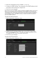
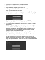
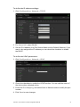
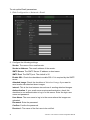
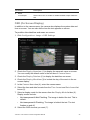
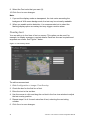
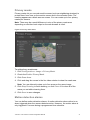
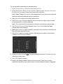
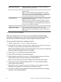
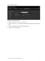
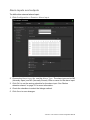
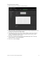
1
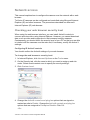
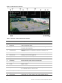
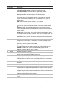
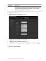
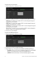
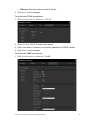
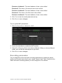
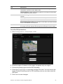
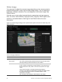
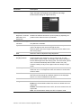
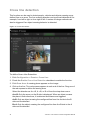
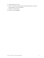
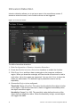
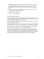
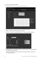
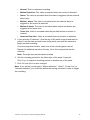
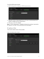
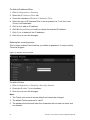
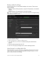
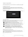
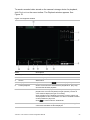
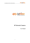
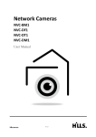
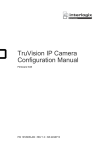
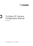
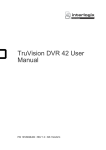
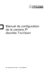
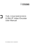
TruVision 11/31 Series IP Camera Configuration Manual P/N 1072856C • REV 1.0 • ISS 10FEB15 TruVision 11/31 Series IP Camera Configuration Manual 1 Copyright © 2015 United Technologies Corporation. Interlogix is part of UTC Building & Industrial Systems, a unit of United Technologies Corporation. All rights reserved. Trademarks and patents Manufacturer Trade names used in this document may be trademarks or registered trademarks of the manufacturers or vendors of the respective products. Interlogix. 2955 Red Hill Avenue, Costa Mesa, CA 92626-5923, USA Authorized EU manufacturing representative: UTC Fire & Security B.V. Kelvinstraat 7, 6003 DH Weert, The Netherlands Contact information For contact information, see www.utcfireandsecurity.com or www.utcfssecurityproducts.eu. Content Introduction 3 Network access 5 Checking your web browser security level 5 Accessing the camera over the internet 7 Overview of the camera web browser 7 Camera configuration 9 Configuration menu overview 9 Local configuration 10 System time 12 Network settings 13 Recording parameters 23 Video image 26 OSD (On Screen Display) 29 Overlay text 30 Privacy masks 31 Motion detection alarms 31 Tamper-proof alarms 35 Exception alarms 36 Alarm inputs and outputs 38 Cross line detection 40 Intrusion Detection 42 Snapshot parameters 43 NAS settings 45 Storage devices 46 Recording schedule 47 Camera management 50 User management 50 RTSP authentication 52 IP address filter 53 Restore default settings 55 Import/export a configuration file 55 Upgrade firmware 56 Reboot camera 57 Camera operation 58 Logging on and off 58 Live view mode 58 Playing back recorded video 58 Searching event logs 61 TruVision 11/31 Series IP Camera Configuration Manual 1 Index 64 2 TruVision 11/31 Series IP Camera Configuration Manual Introduction This is the user manual for TruVision 11/31 Series IP camera models: IP mini bullet camera: TVB-1101 (1.3MPX Bullet, 6mm lens, PAL) TVB-3101 (1.3MPX Bullet, 6mm lens, NTSC) TVB-1102 (3MPX Bullet, 6mm lens, PAL) TVB-3102 (3MPX Bullet, 6mm lens, NTSC) TVB-1103 (1.3MPX Bullet, 4mm lens, PAL) TVB-3103 (1.3MPX Bullet, 4mm lens, NTSC) IP VF bullet camera: TVB-1104 (1.3MPX Bullet, 2.8 to 12mm VF Lens, PAL) TVB-3104 (1.3MPX Bullet, 2.8 to 12mm VF Lens, NTSC) TVB-1105 (3MPX Bullet, 2.8 to 12mm VF Lens, PAL) TVB-3105 (3MPX Bullet, 2.8 to 12mm VF Lens, NTSC) IP mini dome camera: TVD-1101 (1.3MPX Plastic Mini Dome, PoE, PAL) TVD-3101 (1.3MPX Plastic Mini Dome, PoE, NTSC) TVD-1102 (3MPX Plastic Mini Dome, PoE, PAL) TVD-3102 (3MPX Plastic Mini Dome, PoE, NTSC) TVD-1105 (1.3MPX IP IR Outdoor Mini Dome, PoE/12VDC, PAL) TVD-3105 (1.3MPX IP IR Outdoor Mini Dome, PoE/12VDC, NTSC) TVD-1106 (3MPX IP IR Outdoor Mini Dome, PoE/12VDC, PAL) TVD-3106 (3MPX IP IR Outdoor Mini Dome, PoE/12VDC, NTSC) IP VF mini dome camera: TVD-1103 (1.3MPX VF Mini Dome, PAL) TVD-3103 (1.3MPX VF Mini Dome, NTSC) TVD-1104 (3MPX VF Mini Dome, PAL) TVD-3104 (3MPX VF Mini Dome, NTSC) IP wedge camera: TVW-1101 (1.3MPX Wedge, 2.8mm lens, PAL) TVW-3101 (1.3MPX Wedge, 2.8mm lens, NTSC) TVW-1102 (3MPX Wedge, 2.8mm lens, PAL) TruVision 11/31 Series IP Camera Configuration Manual 3 TVW-3102 (3MPX Wedge, 2.8mm lens, NTSC) IP wireless wedge camera: TVW-1103 (1.3MPX wireless, 2.8mm lens, Grey, PAL) TVW-3103 (1.3MPX wireless, 2.8mm lens, Grey, NTSC) TVW-1104 (1.3MPX wireless, 2.8mm lens, White, PAL) TVW-3104 (1.3MPX wireless, 2.8mm lens, White, NTSC) TVW-1105 (3MPX wireless, 2.8mm lens, Grey, PAL) TVW-3105 (3MPX wireless, 2.8mm lens, Grey, NTSC) TVW-1106 (3MPX wireless, 2.8mm lens, White, PAL) TVW-3106 (3MPX wireless, 2.8mm lens, White, NTSC) 4 TruVision 11/31 Series IP Camera Configuration Manual Network access This manual explains how to configure the camera over the network with a web browser. TruVision IP cameras can be configured and controlled using Microsoft Internet Explorer (IE) and other browsers. The procedures described use Microsoft Internet Explorer (IE) web browser. Checking your web browser security level When using the web browser interface, you can install ActiveX controls to connect and view video using Internet Explorer. However, you cannot download data, such as video and images due to the increased security measure. Consequently you should check the security level of your PC so that you are able to interact with the cameras over the web and, if necessary, modify the Active X settings. Configuring IE ActiveX controls You should confirm the ActiveX settings of your web browser. To change the web browser’s security level: 1. In Internet Explorer, click Internet Options on the Tools menu. 2. On the Security tab, click the zone to which you want to assign a web site under “Select a web content zone to specify its security settings”. 3. Click Custom Level. 4. Change the ActiveX controls and plug-ins options that are signed or marked as safe to Enable. Change the ActiveX controls and plug-ins options that are unsigned to Prompt or Disable. Click OK. - Or - TruVision 11/31 Series IP Camera Configuration Manual 5 Under Reset Custom Settings, click the security level for the whole zone in the Reset To box, and select Medium. Click Reset. Then click OK to the Internet Options Security tab window. 5. Click Apply in the Internet Options Security tab window. Windows 7 and 8 users Internet Explorer for Windows 7 and Windows 8 operating systems have increased security measures to protect your PC from any malicious software being installed. To have complete functionality of the web browser interface with Windows 7 and Windows 8, do the following: • Run the Browser interface as an administrator in your workstation • Add the camera’s IP address to your browser’s list of trusted sites To add the camera’s IP address to Internet Explorer’s list of trusted sites: 1. Open Internet Explorer. 2. Click Tools, and then Internet Options. 3. Click the Security tab, and then select the Trusted sites icon. 4. Click the Sites button. 5. Clear the “Require server verification (https:) for all sites in this zone box. 6. Enter the IP address in the “Add this website to the zone” field. 7. Click Add, and then click Close. 8. Click OK in the Internet Options dialog window. 9. Connect to the camera for full browser functionality. 6 TruVision 11/31 Series IP Camera Configuration Manual Accessing the camera over the internet Use the web browser to access and configure the camera over the internet. It is recommended that you change the administrator password once the setup is complete. Only authorized users should be able to modify camera settings. See “User management” on page 50 for further information. To access the camera online: 1. In the web browser enter the camera’s IP address (default is 192.168.1.70). Use the tool, TruVision Device Finder, enclosed on the CD to find the IP address of the camera. The Login dialog box appears. Note: Ensure that the Active X controls are enabled. 2. Enter your user name and password. User name: admin Password: 1234 3. Click Login. The web browser window appears in live view mode. Overview of the camera web browser The camera web browser lets you view, record, and play back recorded videos as well as manage the camera from any PC with Internet access. The browser’s easy-to-use controls give you quick access to all camera functions. See Figure 1 on page 8. If there is more than one camera connected over the network, open a separate web browser window for each individual camera. TruVision 11/31 Series IP Camera Configuration Manual 7 Figure 1: Web browser interface Table 1: Overview of the web browser interface Name Description 1. Live view Click to view live video. 2. Playback Click to play back video. 3. Log Click to search for event logs. There are three main types: Alarm, Exception and Operation. 4. Configuration Click to display the configuration window for setting up the camera. 5. Viewer View live video. Time, date and camera name are displayed here. 6. Current user Displays current user logged on. 7. Logout Click to log out from the system. This can be done at any time. 8. Aspect ratio Select the aspect 9. Streaming Switch between main stream and substream. 10. Start/stop live view Click to start/stop live view. 11. Audio Adjust volume. 12. Bidirectional audio Turn on/off microphone. 13. Capture Click to take a snapshot of the video. The snapshot will be saved to the default folder in JPEG format. 14. Start/stop recording Click to record live video. 15. Digital Zoom Click to enable digital zoom. 16. PTZ control Control pan, tilt, zoom actions, and set up presets and tour. 8 TruVision 11/31 Series IP Camera Configuration Manual Camera configuration This chapter explains how to configure the cameras through a web browser. Once the camera hardware has been installed, configure the camera’s settings through the web browser. You must have administrator rights in order to configure the cameras over the internet. The camera web browser lets you configure the camera remotely using your PC. Web browser options may vary depending on camera model. There are two main folders in the configuration panel: Local configuration Configuration Configuration menu overview Use the Configuration panel to configure the server, network, camera, alarms, users, transactions and other parameters such as upgrading the firmware. See Figure 2 and Table 2 below for descriptions of the configuration folders available. Figure 2: Configuration panel (Device Information tab selected) Table 2: Overview of the Configuration panel Configuration folders Description 1. System Defines the camera name and number. Displays basic information on the device including SN and the current firmware version, time settings, maintenance, and serial port parameters. See “System time” on page 12, “Restore default settings” on page 55, and “Upgrade firmware” on page 56 for more information. TruVision 11/31 Series IP Camera Configuration Manual 9 Configuration folders Description 2. Network Defines the network parameters required to access the camera over the internet. See “Network settings” on page 13 for more information. 3. Video/Audio Defines recording parameters. See “Recording parameters” on page 23 for more information. 4. Image Defines the image parameters, OSD settings, overlay text, and privacy mask. See “Video image” on page 26, “OSD (On Screen Display)” on page 29, “Overlay text” on page 30, and “Privacy masks” on page 31 for more information. 5. Security Defines who can use the camera, their passwords and access privileges, RTSP authentication, IP address filter, and Telnet access. See “Camera management” on page 50 for more information. 6. Events Defines motion detection, tamper-proof, alarm input/output, exception, and snapshot configuration. See “Motion detection alarms” on page 31, “Tamper-proof alarms” on page 35, “Exception alarms” on page 36, and “Snapshot parameters” on page 43 for more information. 7. Storage Defines recording schedule, storage management, and NAS configuration. See “NAS settings” on page 45, “Storage devices” on page 46, and “Recording schedule” on page 47 for more information. Local configuration Use the Local menu to manage the protocol type, live view performance and local storage paths. In the Configuration panel, click Local Configuration to display the local configuration window. See Figure 3 and Table 3 below for descriptions of the different menu parameters. 10 TruVision 11/31 Series IP Camera Configuration Manual Figure 3: Example of a configuration window (Local configuration shown) Table 3: Overview of the Local configuration window Parameters Description Live View Parameters 1. Protocol Specifies the network protocol used. Options include: TCP, UDP, MULTICAST and HTTP. 2. Live View Performance Specifies the transmission speed. Options include: Shortest Delay or Auto. 3. Rules It refers to the rules on your local browser. Specify whether or not to display the colored marks when motion detection, face detection, and intrusion detection are triggered. For example, when the rules option is enabled and a face is detected, the face will be marked with a green rectangle in live view. 4. Image Format Choose the image format for a snapshot: JPEG or BMP. Record File Settings 5. Record File Size Specifies the maximum file size. Options include: 256 MB, 512 MB and 1G. 6. Save Record Files to Specifies the directory for recorded files. 7. Save Downloaded Files to Specifies the directory for downloaded files. Picture and Clip Settings 8. Save Snapshots In Live View Specifies the directory for saving snapshots in live view mode. To TruVision 11/31 Series IP Camera Configuration Manual 11 Parameters Description 9. Save Snapshots When Playback To Specifies the directory for saving snapshots in playback mode. 10. Save Clips To Specifies the directory for saving video clips in playback mode. System time NTP (Network Time Protocol) is a protocol for synchronizing the clocks of network devices, such as IP cameras and computers. Connecting network devices to a dedicated NTP time server ensures that they are all synchronized. To define the system time and date: 1. Click Configuration > System > Time Settings. 2. From the Time Zone drop-down menu, select the time zone that is the closest to the camera’s location. 3. Under Time Sync, check one of the options for setting the time and date: Synchronize with an NTP server: Check the NTP enable box and enter the server NTP address. The time interval can be set from 1 to 10080 minutes. - Or Set manually: Enable the Manual Time Sync function and then click set the system time from the pop-up calendar. to Note: You can also check the Sync with computer time checkbox to synchronize the time of the camera with the time of your computer. 12 TruVision 11/31 Series IP Camera Configuration Manual 4. Check Enable DST to enable the DST function, and set the date of the DST period. 5. Click Save to save changes. Network settings Accessing the camera through a network requires that you define certain network settings. Use the “Network” folder to define the network settings. See Figure 4 and Table 4 below for further information. Figure 4: Network window (TCP/IP tab shown) Table 4: Network parameters Parameters 1. TCP/IP Description Select NIC: Specifies LAN or WLAN for different network. NIC Type: Specifies the NIC type. Default is Auto. Other options include: 10M Half-dup, 10M Full-dup, 100M Half-dup and 100M Full-dup. DHCP: Enable to automatically obtain an IP address and other network settings from that server. IPv4 Address: Specifies the IPv4 address of the camera. IPv4 Subnet Mask: Specifies the IPv4 subnet mask. IPv4 Default Gateway: Specifies the IPv4 gateway IP address. IPv6 Mode: Specifies the IPv6 mode, including Manual, DHCP and Router Advertisement. TruVision 11/31 Series IP Camera Configuration Manual 13 Parameters Description IPv6 Address: Specifies the IPv6 address of the camera. IPv6 Subnet Prefix Length: Specifies the IPv6 prefix length. IPv6 Default Gateway: Specifies the IPv6 gateway IP address. Mac Address: Specifies the mac address of the camera. MTU: Specifies the valid value range of MTU. Default is 1500. Multicast Address: Specifies a D-class IP address between 224.0.0.0 to 239.255.255.255. Only specify this option if you are using the multicast function. Some routers prohibit the use of multicast function in case of a network storm. DNS server: Specifies the DNS server for your network. 2. Port HTTP Port: The HTTP port is used for remote internet browser access. Enter the port used for the Internet Explorer (IE) browser. Default value is 80. RTSP Port: RTSP (Real Time Streaming Protocol) is a network control protocol designed for use in entertainment and communications systems to control streaming media servers. Enter the RTSP port value. The default port number is 554. HTTPS Port: HTTPS (Hyper Text Transfer Protocol Secure) allows video to be securely viewed when using a browser. Enter the HTTPS port, value. The default port number is 443. Server Port: This is used for remote client software access. Enter the server port value. The default port number is 8000. 3. DDNS DDNS is a service that maps Internet domain names to IP addresses. It is designed to support dynamic IP addresses, such as those assigned by a DHCP server. Specifies IP server, DynDNS, and ezDDNS. DynDNS (Dynamic DNS): Enter the user name and password registered to the DynDNS web site. The domain name is that of the DynDNS web site. ezDDNS: Enter the host name. It will automatically register it online. IPServer: Enter the address of the IP Server. 4. PPPoE Retrieves a dynamic IP address. 5. SNMP SNMP is a protocol for managing devices on networks. Enable SNMP to get camera status and parameter related information. 6. QoS QoS (Quality of Service) can help solve the network delay and network congestion by configuring the priority of data sending. Enable the option in order to solve network delay and network congestion by configuring the priority of data sending. 7. FTP Enter the FTP address and folder to which snapshots of the camera can be uploaded. 8. Wi-Fi Specifies the wireless network connection parameters. 9. UPnP The UPnP (Universal Plug and Play) protocol allows devices to connect seamlessly and to simplify the implementation of networks in the home and corporate environments. With the function enabled, you do not need to configure the port mapping for each port, and the camera is connected to the Wide Area Network (WAN) via the router. Enable and set the friendly name detected. 10. 14 Email Specifies the email address to which messages are sent when an alarm occurs. TruVision 11/31 Series IP Camera Configuration Manual Parameters Description 11. The UPnP (Universal Plug and Play) protocol allows devices to connect seamlessly and to simplify the implementation of networks in the home and corporate environments. With the function enabled, you do not need to configure the port mapping for each port, and the camera is connected to the Wide Area Network (WAN) via the router. NAT Enable and set the friendly name detected. To define the TCP/IP parameters: 1. Click Configuration > Network > TCP/IP. 2. Configure the NIC settings, including the NIC Type, IPv4 settings, IPv6 settings, MTU settings, and Multicast Address. 3. If the DHCP server is available, check DHCP. 4. If the DNS server settings are required for some applications (e.g., sending email), you should configure the Preferred DNS Server or Alternate DNS Server. 5. Click Save to save changes. TruVision 11/31 Series IP Camera Configuration Manual 15 To define the port parameters: 1. Click Configuration > Network > Port. 2. Set the HTTP port, RTSP port, HTTPS port and Server port of the camera. HTTP Port: The default port number is 80. It can be changed to any port number that is not occupied. RTSP Port: The default port number is 554. It can be changed to any port number in the range from 1 to 65535. HTTPS Port: The default port number is 443. It can be changed to any port number that is not occupied. Server Port: The default server port number is 8000. It can be changed to any port number in the range from 2000 to 65535. 3. Click Save to save changes. To define the DDNS parameters: 1. Click Configuration > Network > DDNS. 2. Check Enable DDNS to enable this feature. 3. Select DDNS Type. Two options are available: DynDNS and IPServer. 16 • DynDNS: Enter the user name and password registered to the DynDNS web site. The domain name is that of the DynDNS web site. • ezDDNS: Enter the host name. It will automatically register it online. TruVision 11/31 Series IP Camera Configuration Manual • IPServer: Enter the address of the IP Server. 4. Click Save to save changes. To define the PPPoE parameters: 1. Click Configuration > Network > PPPoE. 2. Check Enable PPPoE to enable this feature. 3. Enter User Name, Password, and Confirm password for PPPoE access. 4. Click Save to save changes. To define the SNMP parameters: 1. Click Configuration > Network > SNMP. TruVision 11/31 Series IP Camera Configuration Manual 17 2. Select the corresponding version of SNMP: v1, v2c or v3. 3. Configure the SNMP settings. The configuration of the SNMP software should be the same as the settings you configure here. 4. Click Save to save changes. Note: Before setting the SNMP, please download the SNMP software and ensure that you can receive the camera information via the SNMP port. By setting the Trap Address, the camera can send the alarm event and exception messages to the surveillance center. The SNMP version you select should be the same as that of the SNMP software. To define the QoS parameters: 1. Click Configuration > Network > QoS. 2. Configure the QoS settings, including Video / Audio DSCP, Event / Alarm DSCP and Management DSCP. The valid value range of the DSCP is 0-63. The bigger the DSCP value is the higher the priority is. 3. Click Save to save changes. To define the FTP parameters: 1. Click Configuration > Network > FTP. 18 TruVision 11/31 Series IP Camera Configuration Manual 2. Configure the FTP settings, including server address, port, user name, password, directory, and upload type. Anonymous: Check the checkbox to enable the anonymous access to the FTP server. Directory: In the Directory Structure field, you can select the root directory, parent directory and child directory. When the parent directory is selected, you have the option to use the Device Name, Device Number or Device IP for the name of the directory; and when the child directory is selected, you can use the Camera Name or Camera No. as the name of the directory. Upload type: To enable uploading the snapshots to the FTP server. 3. Click Save to save changes. To define the Wi-Fi parameters: 1. Click Configuration > Network > Wi-Fi. Note: When configuring the Wi-Fi settings for the first time, connect the camera to the router via a network cable and then open the web browser to complete the Wi-Fi setup by clicking Save. When the Wi-Fi Status changes from “Disconnected” to “Connected”, the wireless connection is successfully set up. TruVision 11/31 Series IP Camera Configuration Manual 19 2. Click Search to search the online wireless connections. 3. Click to choose a wireless connection on the list. 4. Select the Network Mode as Manage or Ad-hoc In Manage mode, the Security Mode of is automatically shown when you select a wireless connection from the list. Ad-Hoc Mode is used when accessing the camera via a PC without going through a wireless router. You can identify the camera SSID and specify the Security Mode as needed. 5. Select the required Security Mode: Not-encrypted, WEP, WPA-personal, WPA-enterprise, WPA2-personal, or WPA2-enterprise. 6. For quick Wi-Fi setup, please check the Enable WPS checkbox to enable WPS function. PBC Mode: Push the WPS button on the wireless router, and the WPS indicator will flash. (The WPS settings may be different per device. Please refer to the wireless router User Manual for details). Then check the PBC checkbox and click the Connect button. The camera and the wireless network router are connected automatically. PIN Mode: Check the wireless router device and find the PIN code, which is printed on a sticker or printed on the device. Enter the PIN code in the Router PIN Code bar and check the Use router PIN code. Then click Connect to connect the camera to the wireless router. You can generate the PIN code on the camera side and configure the wireless router to finish the connection setting. (Please check the wireless router User Manual for details). Please note that the PIN code expiration time is 120 seconds. 20 TruVision 11/31 Series IP Camera Configuration Manual To define the IP address settings: 1. Click Configuration > Network > TCP/IP. 2. For Select NIC, select WLAN. 3. Set the IPv4 address, the IPv4 Subnet Mask and the Default Gateway. If you want to be assigned the IP address you can check the checkbox to enable the DHCP. To define the UPnP parameters: 1. Click Configuration > Network > UPnP. 2. Check the checkbox to enable the UPnP function. You can edit the name of the device when detected online. 3. Check the Port Mapping, and select Auto or Manual mode to modify the port number. 4. Click Save to save changes. TruVision 11/31 Series IP Camera Configuration Manual 21 To set up the Email parameters: 1. Click Configuration > Network > Email. 2. Configure the following settings: Sender: The name of the email sender. Sender’s Address: The email address of the sender. SMTP Server: The SMTP Server IP address or host name. SMTP Port: The SMTP port. The default is 25. Enable SSL: Check the checkbox to enable SSL if it is required by the SMTP server. Attached Image: Check the checkbox of Attached Image if you want to send emails with attached alarm images. Interval: This is the time between two actions of sending attached images. Authentication: If your email server requires authentication, check this checkbox to use authentication to log in to this server. Enter the login user name and password. User Name: The user name to log in to the server where the images are uploaded. Password: Enter the password. Confirm: Confirm the password. Receiver1: The name of the first user to be notified. 22 TruVision 11/31 Series IP Camera Configuration Manual Receiver’s Address1: The email address of user to be notified. Receiver2: The name of the second user to be notified. Receiver’s Address2: The email address of user to be notified. Receiver3: The name of the third user to be notified. Receiver’s Address3: The email address of user to be notified. 3. Click Test to test the email parameters set up. 4. Click Save to save changes. To set up the NAT parameters: 1. Click Configuration > Network > NAT. 2. Check the checkbox to enable the NAT function. 3. Select Port Mapping Mode to be Auto or Manual. When you choose Manual mode, you can set the external port as you want. 4. Click Save to save changes. Recording parameters You can adjust the video and audio recording parameters to obtain the picture quality and file size best suited to your needs. Figure 5 and Table 5 below list the video and audio recording options you can configure for the camera. TruVision 11/31 Series IP Camera Configuration Manual 23 Figure 5: Video/Audio Settings menu (Video tab shown) Table 5: Video setting parameters Tab 1. Description Video Stream Type: Specifies the streaming method used. Options include: Main Stream (Normal) and Sub Stream. Video Type: Specifies the stream type you wish to record. Select Video Stream to record video stream only. Select Video&Audio to record both video and audio streams. Note: Video&Audio is only available for those camera models that support audio. Resolution: Specifies the recording resolution. A higher image resolution provides a higher image quality but also requires a higher bit rate. The resolution options listed depend on the type of camera and on whether main or sub stream is being used. Note: Resolutions can vary depending on the camera model. Bitrate Type: Specifies whether variable or fixed bit rate is used. Variable produces higher quality results suitable for video downloads and streaming. Default is Constant. Video Quality: Specifies the quality level of the image. It can be set when variable bit rate is selected. Options include: Lowest, Lower, Medium, Higher and Highest. Frame Rate: Specifies the frame rate for the selected resolution. The frame rate is the number of video frames that are shown or sent per second. Note: The maximum frame rate depends on the camera model and selected resolution. Please check the camera specifications in its datasheet. Max bit rate: Specifies the maximum allowed bit rate. A high image resolution requires that a high bit rate must also be selected. Video Encoding: Specifies the video encoder used. 24 TruVision 11/31 Series IP Camera Configuration Manual Tab Description Profile: Different profile indicates different tools and technologies used in compression. Options include: Main Profile. I Frame Interval: A video compression method. It is strongly recommended not to change the default value 50. 2. Audio Audio Encoding: G.722.1, G.711ulaw, G.711alaw, MP2L2 and G.726 are optional. Audio Input: “MicIn” is selectable for the built-in microphone. Input Volume: Specifies the volume from 0 to 100. Environmental Noise Filter: Set it as OFF or ON. When you set the function on the noise detected can be filtered. 3. ROI Enable to assign more encoding resource to the region of interest to increase the quality of the ROI whereas the background information is less focused. To define ROI parameters: 1. Click Configuration > Video/Audio > ROI. 2. Draw the region of interest on the image. It supports only one region. 3. Choose the stream type to set the ROI encoding. 4. Check the Fixed Region to manually configure the area. You can choose the Image Quality Enhancing level for ROI encoding, and you can also name the ROI area. 5. Click Save to save changes. TruVision 11/31 Series IP Camera Configuration Manual 25 Video image You may need to adjust the camera image depending on the camera model or location background in order to get the best image quality. You can adjust the brightness, contrast, saturation, hue, and sharpness of the video image. See Figure 6 below. Use this menu to also adjust camera behavior parameters such as exposure time, iris mode, video standard, day/night mode, image flip, WDR, digital noise reduction, and white balance. See Figure 6 and Table 6 below for more information. Figure 6: Camera image settings menu (Auto-switch option selected for Switch Day and Night Settings) Table 6: Image parameters Parameter Description 1. Switch Day and Night Settings Auto-Switch The camera automatically switches between day and night mode. All image settings remain the same for both modes. Schedule Switch The camera switches between the day and night modes according to the schedule configured (see figure below). The start and end times shown are for day mode. The other time period is for night mode. There are three tabs to configure the day/night settings: Common: The settings are identical for both day and night modes for Image Adjustment, Exposure, Day/Night Switch, Video Adjustment, and Other. Day: Configure the Backlight, White Balance and Image 26 TruVision 11/31 Series IP Camera Configuration Manual Parameter Description Enhancement settings for day mode only. Night: Configure the Backlight, White Balance and Image Enhancement settings for night mode only. 2. Image Adjustment Brightness, Contrast Saturation, Hue, Sharpness Modifies the different elements of picture quality by adjusting the position of the values for each of parameter. 3. Exposure Settings Iris Mode Only Manual is available. Exposure Time The exposure time controls the length of time that the aperture is open to let light into the camera through the lens. Select a higher value if the image is dark and a lower value to see fast moving object. Gain Select the value to adjust the image brightness. 4. Day/Night Switch Day/Night Switch Defines whether the camera is in day or night mode. The day (color) option could be used, for example, if the camera is located indoors where light levels are always good. There are three options: Auto: Camera automatically detects which mode to use; Day: Camera is always in day mode; Night: Camera is always in night mode. Sensitivity If you choose Auto Day/Night switch, you can choose the sensitivity value from 0 to 7. The higher the value, the easier it is for the D/N mode to switch. Switch Time Only available when Auto D/N switch mode is selected. The filtering time refers to the interval time between switchover the day/night switch. You can set it between 5 and 120 s. Smart IR When enabled, it can avoid over exposure issue. IR Light Select On/OFF to Enable/disable IR. Enable: the IR illuminators will be ON, when the camera turns into night mode. Disable: the IR illuminators will be OFF, when the camera turns into night mode Note: The IR illuminators always are OFF in Daytime mode. TruVision 11/31 Series IP Camera Configuration Manual 27 Parameter Description 5. Backlight Settings BLC Area If you focus on an object against strong backlight, the object will be too dark to be seen clearly. BLC compensates light to the object in the front to make it clear. OFF, Up, Down, Left, Right, and Center are selectable. DWDR When enabled, this feature (wide dynamic range) allows you to see details of objects in shadows or details of objects in bright areas of frames that have high contrast between light and dark areas. 6. White Balance White Balance White balance (WB) tells the camera what the color white looks like. Based on this information, the camera will then continue to display all colors correctly even when the color temperature of the scene changes such as from daylight to fluorescent lighting, for example. Select one of the options: AWB1: Apply for small range of 2500 to 9500K, for simple environments. Locked WB: Locks the WB to the current environment color temperature. Incandescent Lamp: For use with incandescent lighting. Warm Light Lamp: For use where the indoor light is warm. Natural Light: For use with natural light. Fluorescent Lamp: For use where there are fluorescent lamps installed near the camera. 7. Image Enhancement Digital Noise Reduction Digital noise reduction (DNR) reduces noise, especially in low light conditions, to improve image performance. Options include: ON or OFF. Noise Reduction Level Set the level of noise reduction. Higher value has a stronger noise reduction. Default is 50. 8. Video Adjustment Mirror It mirrors the image so you can see it inversed. Left/Right, Up/Down, Center, and OFF are selectable. Default is OFF. Hallway View To make a complete use of the 16:9 aspect ratio, enable the rotate function when you use the camera in a narrow view scene. During installing, turn the camera to 90 degrees or rotate the 3-axis lens to 90 degrees, and then set the rotate mode as On. You will get a normal view of the scene with 9:16 aspect ratio that ignores needless information such as the walls. Default is OFF. Scene Mode Select indoor or outdoor mode. Default is Outdoor mode. Indoor: Locks the exposure time. Outdoor: Adjusts the exposure time to prevent the iris being too small in strong light. Video Standard 28 50 Hz and 60 Hz are selectable. Choose according to the different video standards; normally 50 Hz for PAL standard and 60 Hz for NTSC standard. TruVision 11/31 Series IP Camera Configuration Manual Parameter Description 9. Other Local Output Select ON or OFF to enable or disable the BNC output. Default is ON. OSD (On Screen Display) In addition to the camera name, the camera also displays the system date and time on screen. You can also define how the text appears on screen. To position the date/time and name on screen: 1. Click Configuration > Image > OSD Settings. 2. Check the Display Name box (1) to display the camera’s name on screen. You can modify the default name in the text box of Camera Name. 3. Check the Display Date box (2) to display the date/time on screen. 4. Check the Display Week box (3) to include the day of the week in the onscreen display. 5. In the Camera Name box (4), enter the camera name. 6. Select the time and date formats from the Time format and Date format list boxes (5). 7. Select a display mode for the camera from the Display Mode list box (6). Display modes include: • Not transparent & Not Flashing. The image is behind the text. This is default. • Not transparent & Flashing. The image is behind the text. The text flashes on and off. 8. Select the OSD size that you want (7). TruVision 11/31 Series IP Camera Configuration Manual 29 9. Select the Font color that you want (8). 10. Click Save to save changes. Note: 1. If you set the display mode as transparent, the text varies according the background. With some backgrounds, the text may be not easily readable. 2. When you enable motion detection, it is recommended not to select the flashing display option as overlay text may trigger a motion alarm. Overlay text You can add up to four lines of text on screen. This option can be used, for example, to display emergency contact details. Each text line can be positioned anywhere on screen. See Figure 7 below. Figure 7: Text overlay menu To add on-screen text: 1. Click Configuration > Image >Text Overlay. 2. Check the box for the first line of text. 3. Enter the text in the text box. 4. Use the mouse to click and drag the red text in the live view window to adjust the text overlay position. 5. Repeat steps 2 to 4 for each extra line of text, selecting the next string number. 6. Click Save to save changes. 30 TruVision 11/31 Series IP Camera Configuration Manual Privacy masks Privacy masks let you conceal sensitive areas (such as neighboring windows) to protect them from view on the monitor screen and in the recorded video. The masking appears as a blank area on screen. You can create up to four privacy masks per camera. Note: There may be a small difference in size of the privacy mask area depending on whether local output or the web browser is used. Figure 8: Privacy mask menu To add privacy mask area: 1. Click Configuration > Image > Privacy Mask. 2. Check the Enable Privacy Mask. 3. Click Draw Area. 4. Click and drag the mouse in the live video window to draw the mask area. Note: You are allowed to draw up to four areas on the same image. 5. Click Stop Drawing to finish drawing, or click Clear All to clear all of the areas you set without saving them. 6. Click Save to save changes. Motion detection alarms You can define motion detection alarms. A motion detection alarm refers to an alarm triggered when the camera detects motion. However, the motion alarm is only triggered if it occurs during a programmed time schedule. TruVision 11/31 Series IP Camera Configuration Manual 31 Select the level of sensitivity to motion as well as the target size so that only objects that could be of interest can trigger a motion recording. For example, the motion recording is triggered by the movement of a person but not that of a cat. You can define the area on screen where the motion is detected, the level of sensitivity to motion, the schedule when the camera is sensitive to detecting motion as well as which methods are used to alert you to a motion detection alarm. You can also enable dynamic analysis for motion. When there is motion, the area will be highlighted as green. Figure 9: Motion detection menu Defining a motion detection alarm requires the following tasks: 1. Area settings: Define the on-screen area that can trigger a motion detection alarm and the detection sensitivity level. 2. Arming schedule: Define the schedule during which the system detects motion. 3. Recording schedule: Define the schedule during which motion detection can be recorded. See “Recording schedule” on page 47 for further information. 4. Linkage: Specify the method of response to the alarm. In order to detect the moving objects accurately and reduce the false alarm rate, normal configuration and advanced configuration are selectable for different motion detection environments. 32 TruVision 11/31 Series IP Camera Configuration Manual To set up motion detection as normal mode: 1. Click Configuration > Events > Motion Detection. 2. Check the Enable Motion Detection box. Check Enable Dynamic Analysis for Motion if you want to see where has motion real-time. Note: Select Disable for rules in local configuration menu if you don’t want the detected objected displayed with the rectangles. 3. Select Normal mode from the drop down menu. 4. Click Draw Area. Click and drag the mouse on the live video image to draw an area sensitive to motion detection. Note: You can draw up to eight motion detection areas on the same image. 5. Click Stop Drawing to finish drawing. Click Clear All to delete all areas marked and restart drawing. 6. Move the Sensitivity slider to set the sensitivity of the detection. All areas will have the same sensitivity level. 7. Click Edit to edit the arming schedule. See the picture below for the editing interface of the arming schedule. 8. Choose the day and click schedule to other days. to set the detailed time period. You can copy the 9. Click OK to save changes. 10. Specify the linkage method when an event occurs. Check one or more response methods for the system when a motion detection alarm is triggered. TruVision 11/31 Series IP Camera Configuration Manual 33 Notify Alarm Recipient Send an exception or alarm signal to remote management software when an event occurs. Send Email Sends an email to a specified address when there is a motion detection alarm. Note: You must configure email settings before check this option. See “To set up the Email parameters:” on page 22. If you want to send the event snapshot together with the email, you should check the Attached Snapshot option. Upload Snapshot Capture the image when an alarm is triggered and upload the picture to NAS or FTP server. Note: If you want to upload the snapshot to NAS, you must configure NAS settings, If you want to upload the snapshot to FTP, you must configure the FTP settings. Please ensure that the Upload Type option is enabled. Trigger Channel Triggers the recording to start in the camera. Trigger Alarm Output Trigger external alarm outputs when an event occurs. Note: This option is only supported by cameras that support alarm output. 11. Click Save to save changes. When you choose Advanced mode, you can set different sensitivities and proportions on different areas. If you choose Auto-Switch or Schedule-Switch, you can also set different settings for day and night or different periods. To set up motion detection as advanced mode: 1. Click Configuration > Events > Motion Detection. 2. Check the Enable Motion Detection box. Check Enable Dynamic Analysis for Motion if you want to see where has motion real-time. Note: Select Disable for rules in local configuration menu if you don’t want the detected objected displayed with the rectangles. 3. Select Advanced mode from the drop down menu. 4. Select OFF, Auto-switch or Scheduled-switch 5. Select Area No. and click Draw Area. Click and drag the mouse on the live video image to draw an area sensitive to motion detection. Note: You can draw up to 8 motion detection areas on the same image. 6. Click Stop Drawing to finish drawing. Click Clear All to delete all areas marked and restart drawing. 7. Move the Sensitivity and Proportion of Object on Area slider to set the sensitivity and proportion of the detection for different areas 8. Click Edit to edit the arming schedule. See the picture below for the editing interface of the arming schedule. 34 TruVision 11/31 Series IP Camera Configuration Manual 9. Choose the day and click schedule to other days. to set the detailed time period. You can copy the 10. Click OK to save changes. 11. Specify the linkage method when an event occurs. Check one or more response methods for the system when a motion detection alarm is triggered. Notify Alarm Recipient Send an exception or alarm signal to remote management software when an event occurs. Send Email Sends an email to a specified address when there is a motion detection alarm. Upload Snapshot Capture the image when an alarm is triggered and upload the picture to NAS or FTP server. Trigger Channel Triggers the recording to start in the camera. Trigger Alarm Output Trigger external alarm outputs when an event occurs. Note: This option is only supported by cameras that support alarm output. 12. Click Save to save changes. Tamper-proof alarms You can configure the camera to trigger an alarm when the lens is covered and to take an alarm response action. To set up tamper-proof alarms: 1. Click Configuration > Events > Tamper-proof. 2. Check the Enable Tamper-proof box (1). TruVision 11/31 Series IP Camera Configuration Manual 35 3. Move the Sensitivity slider (2) to set the sensitivity of the detection. All areas will have the same sensitivity level. 4. Click Edit to edit the arming schedule for tamper-proof alarms. The arming schedule configuration is the same as that for motion detection. See “To set up motion detection” for more information. 5. Check the checkbox to select the linkage method taken for the tamper-proof. 6. Click Save to save changes. Exception alarms You can set up the camera to notify you when irregular events occur and how you should be notified. These exception alarms include: • HDD Full: All recording space of NAS is full. • HDD Error: Errors occurred while files were being written to the storage, no storage or storage had failed to initialize. • Network Disconnected: Disconnected network cable. • IP Address Conflicted: Conflict in IP address setting. • Invalid Login: Wrong user ID or password used to login to the cameras. 36 TruVision 11/31 Series IP Camera Configuration Manual Figure 10: Exception menu To define exception alarms: 1. Click Configuration > Events > Exception. 2. Under Notification Type, select an exception alarm type from the drop-down list. 3. Check the checkbox to select the linkage method. 4. Click Save to save changes. TruVision 11/31 Series IP Camera Configuration Manual 37 Alarm inputs and outputs To define the external alarm input: 1. Click Configuration > Events > Alarm Input. 2. Choose the Alarm Input No. and the Alarm Type. The alarm type can be NO (Normally Open) and NC (Normally Closed). Enter a name for the alarm input. 3. Click Edit to set the arming schedule for the alarm input. See “Motion detection alarms” on page 31 for more information. 4. Check the checkbox to select the linkage method. 5. Click Save to save changes. 38 TruVision 11/31 Series IP Camera Configuration Manual To define the alarm output: 1. Click Configuration > Events > Alarm Output. 2. Select one alarm output channel from the Alarm Output drop-down list. You can also set a name for the alarm output. 3. The delay time can be set to 5 sec, 10 sec, 30 sec, 1 min, 2 min, 5 min or 10 min. The delay time refers to the time duration that the alarm output remains in effect after alarm occurs. 4. Click Edit to set the arming schedule for the alarm input. See “To set up motion detection” for more information. 5. Click Save to save changes. TruVision 11/31 Series IP Camera Configuration Manual 39 Cross line detection This function can be used to detect people, vehicles and objects crossing a predefined line or an area. The line crossing direction can be set as bidirectional, for example, from left to right or from right to left. A series of linkage methods can also be triggered if an object crossing behavior is detected. Figure 11: Cross line menu To define Cross Line Detection: 1. Click Configuration > Events > Cross Line. 2. Check the Enable Cross Line Detection checkbox to enable the function. 3. Click Draw Area. A crossing plane appears on the image. 4. Click on the line. Two red squares appear at each end of the line. Drag one of the red squares to define the arming area. Select the direction as A<->B, A ->B, or B->A from the drop down menu. A<->B: Only the arrow on the B side is displayed. When an object crosses the plane in both directions, it is detected and alarms are triggered. A->B: Only an object crossing the configured line from the A side to the B side can be detected. B->A: Only the object crossing the configured line from the B side to the A side can be detected. 40 TruVision 11/31 Series IP Camera Configuration Manual 5. Set the sensitivity [1to 100]. 6. Click Edit to set the arming schedule for the alarm input. See “To set up motion detection” for more information. 7. Configure the linkage action. 8. Click Save to save changes. TruVision 11/31 Series IP Camera Configuration Manual 41 Intrusion Detection Intrusion detection allows you to set up an area in the surveillance scene. If someone enters the area, a set of alarm actions can be triggered. Figure 12: Cross line menu To define intrusion detection: 1. Click Configuration > Events > Intrusion Detection. 2. Check the Enable Intrusion Detection checkbox to enable the function. 3. Click Draw Area, and then draw a rectangle on the image as a defense region. When you draw the rectangle, all lines should connect end to end to each other. Up to four areas are supported. You can click Clear to clear the areas you have drawn. The defense region parameters can be set up separately. 4. Choose the Region to be configured. Threshold: Range [0 to10 s]. This is the time threshold of the object to loiter in the region. If you set the value as 0, alarm is triggered immediately when the object enters the region. Sensitivity: Range [1 to 100]. The sensitivity value defines the size of the object that can trigger the alarm. When the sensitivity is high, a small object can trigger the alarm. 42 TruVision 11/31 Series IP Camera Configuration Manual Percentage: Range [1 to 100]. This defines the ratio of the in-region part of the object which can trigger an alarm. For example, when you set the percentage as 50%, half of the object entering the region will trigger the alarm. 5. Click Edit to set the arming schedule for the alarm input. See “To set up motion detection” for more information. 6. Configure the linkage action. 7. Click Save to save changes. Snapshot parameters You can configure scheduled snapshots and event-triggered snapshots. The captured snapshots can be stored in the SD card (if supported) or the NAS. You can also upload the snapshots to an FTP server. You can set up the format, resolution and quality of the snapshots. The quality can below, medium, or high. You must enable the option Enable Timing Snapshot if you want snapshots to be uploaded to the FTP. If you have configured the FTP settings and checked Upload Type in the Network > FTP tab, the snapshots will not be uploaded to the FTP if the Enable Timing Snapshot option is disabled. You must enable the option Enable Event-Triggered Snapshot if you want snapshots to be uploaded to the FTP and NAS when motion detection or an alarm input is triggered. If you have configured the FTP settings and checked Upload Type in the Network > FTP tab for motion detection or an alarm input, the snapshots will not be uploaded to the FTP if this option is disabled. TruVision 11/31 Series IP Camera Configuration Manual 43 Figure 13: Snapshot menu To set up scheduled snapshots: 1. Click Configuration > Storage > Snapshot. 2. Check Enable Timing Snapshot to enable continuous snapshots. 3. Select the desired format of the snapshot, such as JPEG. 4. Select the desired resolution of the snapshot. 5. Select the desired quality of the snapshot: High, Medium or Low. 6. Enter the time interval between two snapshots. Select the unit of time from the dropdown list: milliseconds, seconds, minutes, hour, or day. 7. Set the schedule for when you want snapshots to be taken. Click Edit and desired schedule for each day of the week. 8. Click Save to save changes. 44 TruVision 11/31 Series IP Camera Configuration Manual To set up event-triggered snapshots: 1. Click Configuration > Storage > Snapshot. 2. Check Enable Timing Snapshot to enable continuous snapshots. 3. Select the desired resolution and quality of the snapshot. 4. Enter the time interval between two snapshots. Select the unit of time from the dropdown list: milliseconds, seconds, minutes, hour, or day. 5. Under Capture Number, enter the total number of snapshots that can be taken. 6. Click Save to save changes. NAS settings You can use a network storage system (NAS) to remotely store recordings To configure record settings, please ensure that you have the network storage device within the network. The NAS disk should be available within the network and correctly configured to store the recorded files, log files, etc. Notes: 1. Up to eight NAS disks can be connected to the camera. 2. The recommended capacity of NAS should be between 9G and 2T as otherwise it may cause formatting failure. TruVision 11/31 Series IP Camera Configuration Manual 45 Figure 14: NAS menu To set up a NAS system: 1. Click Configuration > Storage > NAS. 2. Enter the IP address of the network disk, and the NAS file path. 3. Click Save to save changes. Storage devices Use the storage management window to display the capacity, free space available and the working status of the HDD of the NAS and the SD card in the camera. You can also format these storage devices. Before formatting the storage device, stop all recording. Once formatting is completed, reboot the camera as otherwise the device will not function properly. If Overwrite is enabled, the oldest files are overwritten when the storage becomes full. 46 TruVision 11/31 Series IP Camera Configuration Manual To format the storage devices: 1. Click Configuration > Storage > Storage Management. 2. Check the HDD Number column to select the storage. 3. Define the quota percentage for snapshots and recordings, modify the values for each in Percentage of Snapshot and Percentage of Record. 4. Click Format. A window appears to check your formatting permission. 5. Click OK to start formatting. Recording schedule You can define a recording schedule for the camera in the “Record Schedule” window. The recording is saved on to the SD card or NAS in the camera. The camera’s SD card provides a backup in case of network failure. The selected recording schedule applies to all alarm types. Pre-record time The pre-record time is set to start recording before the event. For example, if an alarm triggers recording at 10:00, and the pre-record time is set as 5 seconds, the camera starts to record the event at 9:59:55. The pre-record time can be configured as No Pre-record, 5 s, 10 s, 15 s, 20 s, 25 s, 30 s, or not limited. Post- record time The post-record time is set to stop recording after the event. For example, if an alarm triggered recording ends at 11:00, and the post-record time is set as 5 seconds, the camera records until 11:00:05. The post-record time can be configured as 5 s, 10 s, 30 s, 1 min, 2 min, 5 min, or 10 min. TruVision 11/31 Series IP Camera Configuration Manual 47 To set up a recording schedule: 1. Click Configuration > Storage > Record Schedule. 2. Click the Enable Record Schedule box to enable recording. Note: To disable recording, deselect the option. 3. Click Edit to edit the recording schedule. The following window appears: 4. Select whether the recording will be for the whole week (All Day recording) or for specific days of the week. If you have selected “All day”, select one of the record types to record from the drop-down list box: 48 TruVision 11/31 Series IP Camera Configuration Manual • Normal: This is continuous recording. • Motion Detection: The video is recorded when the motion is detected. • Alarm: The video is recorded when the alarm is triggered via the external alarm input. • Motion | Alarm: The video is recorded when the external alarm is triggered or the motion is detected. • Motion & Alarm: The video is recorded when motion and alarms are triggered at the same time. • Cross line: Video is recorded when the pre-defined line on-screen in crossed. • Intrusion Detection: Video is recorded when an intrusion is detected. 5. If you selected “Customize”, click the day of the week required and then for period 1 set the start and end times during which you want the camera to begin and end recording. From the drop-down list box, select one of the record types to record. Repeat for additional periods in the day. Up to four time periods can be selected. Note: The eight time periods cannot overlap. 6. Set the recording periods for the other days of the week if required. Click Copy to copy the recording periods to another day of the week. 7. Click OK and Save to save changes. Note: If you set the record type to “Motion detection”, “Alarm”, “Cross Line” or “Intrusion detection” you must also define the arming schedule in order to trigger the recording. TruVision 11/31 Series IP Camera Configuration Manual 49 Camera management This chapter describes how to use the camera once it is installed and configured. The camera is accessed through a web browser. User management This section describes how to manage users. You can: Add or delete users Modify permission Modify passwords Only the administrator can manage users. The administrator can create up to 31 individual users for the cameras listed in this manual. For TruVision IP open standard cameras, the administrator can create up to 15 individual users. When new users are added to the list, the administrator can modify permissions and password of each user. See Figure 15 below. Figure 15: User management window Passwords limit access to the camera and the same password can be used by several users. When creating a new user, you must give the user a password. There is no default password provided for all users. Users can modify their passwords. Note: Keep the admin password in a safe place. If you forget it, please contact technical support. Types of users A user’s access privileges to the system are automatically defined by their user type. There are three types of user: 50 TruVision 11/31 Series IP Camera Configuration Manual Admin: This is the system administrator. The administrator can configure all settings. Only the administrator can create and delete user accounts. Admin cannot be deleted. Operator: This user can only change the configuration of his/her own account. An operator cannot create or delete other users. Viewer: This user has the permission to live view, play back and search logs. However, Viewers cannot change any configuration settings. Add and delete users The administrator can create up to 15 users. Only the system administrator can create or delete users. To add a user: 1. Click the User folder to open its window. 2. Select the Add button. The user management window appears. 3. Enter a user name. The name can have up to 16 alphanumeric characters. 4. Assign the user a password. Passwords can have up to 16 alphanumeric characters. 5. Select the type of user from the drop-down list. The options are Viewer and Operator. 6. Assign permissions to users. The options are: Basic Permission Camera Configuration Remote: Parameters Settings Remote: Live View Remote: Log Search/Interrogate Working Status Remote: PTZ Control Remote: Upgrade/Format Remote: Playback Remote: Manual Record Remote: Bidirectional Audio Remote: Shutdown / Reboot Remote: Notify Alarm Recipient / Trigger TruVision 11/31 Series IP Camera Configuration Manual 51 Basic Permission Camera Configuration Alarm Output Remote: Video Output Control Remote: Serial Port Control 7. Click OK to save the settings. To delete a user: 1. Select one user in the User tab. 2. Click Delete button. A message box appears. Note: Only the administrator can delete a user. 3. Click Save to save the changes. Modify user information You can easily change the information about a user such as their name, password and permissions. To modify user information: 1. Select one user in the User tab. 2. Click the Modify button. The user management window appears 3. Change the information required. Note: The user “Admin” can only be changed by entering the admin password. 4. Click Save to save the changes. RTSP authentication You can specifically secure the stream data of live view. 52 TruVision 11/31 Series IP Camera Configuration Manual To define RTSP authentication: 1. Click Configuration > Storage > RTSP Authentication. 2. Select the Authentication type Enable or Disable in the drop-down list to enable or disable the RTSP authentication. 3. Click Save to save the changes. Note: If "RTSP Authentication" is disabled, although the user has no permission for “Remote: Live View", he can still see the live view images. IP address filter This function makes access control possible. Figure 16: IP address filter window TruVision 11/31 Series IP Camera Configuration Manual 53 To define IP Address Filter: 1. Click Configuration > Security. 2. Select the IP Address Filter tab. 3. Check the checkbox of Enable IP Address Filter. 4. Select the type of IP Address Filter in the drop-down list, Forbidden and Allowed are selectable. 5. Click Add to add an IP address. 6. Click Modify or Delete to modify or delete the selected IP address. 7. Click Clear to delete all the IP addrsses. 8. Click Save to save the changes. Defining the security service This function enables Telnet and lets you define its password. It is only used by Technical Support. Figure 17: Enable Telnet window To define Telnet: 1. Click Configuration > Security > Security Service. 2. Check the Enable Telnet checkbox. 3. Click Save to save the changes. Note: 1. The Telnet user name is root as default and cannot be changed. 2. The default Telnet password is “ab12!” 3. The password should have least four characters with at least one letter and one number. 54 TruVision 11/31 Series IP Camera Configuration Manual Restore default settings Use the Default menu to restore default settings to the camera. There are two options available: Restore: Restore all the parameters, except the IP parameters, to the default settings. Default: Restore all the parameters to the default settings. Note: If the video standard is changed, it will not be restored to its original setting when Restore or Default is used. To restore default settings: 1. Click Configuration > System > Maintenance. 2. Click either Restore or Default. A window showing user authentication appears. 3. Enter the admin password and click OK. 4. Click OK in the pop-up message box to confirm restoring operation. Import/export a configuration file The administrator can export and import configuration settings from the camera. This is useful if you want to copy the configuration settings to camera, or if you want to make a backup of the settings. TruVision 11/31 Series IP Camera Configuration Manual 55 To import/export configuration file: 1. Click Configuration > System > Maintenance. 2. Click Browse to select the local configuration file and then click Import to start importing configuration file. 3. Click Export and set the saving path to save the configuration file. Upgrade firmware The camera firmware is stored in the flash memory. Use the upgrade function to write the firmware file into the flash memory. You need to upgrade firmware when it has become outdated. When you upgrade the firmware, all existing settings are unchanged. Only the new features are added with their default settings. The camera will select the corresponding firmware file automatically. Cookies and data in the web browser are automatically deleted when the firmware is updated. To upgrade firmware version: 1. Download on to your computer the latest firmware from our web site at: www.interlogix.com/video/product/truvision-ip-open-standards-outdoorcameras/ - Or www.utcfssecurityproductspages.eu/videoupgrades/ 2. When the firmware file is downloaded to your computer, extract the file to the desired destination. Note: Do not save the file on your desktop. 3. In the Configuration folder, select the System tab. 4. In the Maintenance tab, select the Firmware or Firmware Directory option. Then click the Browse button to locate latest firmware file on your computer. • Firmware directory – Locate the upgrading folder of Firmware files. The camera will choose the corresponding firmware file automatically. • Firmware – Locate the firmware file manually for the camera. Note: Please select Interlogix_Gen_3_ipc.dav for product models listed in “Introduction” on page 3. 5. Click Update. You will receive a prompt asking you to reboot the camera. 6. When the upgrade is finished, the device will reboot automatically. The browser will also be refreshed. 56 TruVision 11/31 Series IP Camera Configuration Manual Reboot camera The camera can be easily rebooted remotely. To reboot the camera through the web browser: 1. Click Configuration > System > Maintenance. 2. Click the Reboot button to reboot the device. 3. Click OK in the pop-up message box to confirm reboot operation. TruVision 11/31 Series IP Camera Configuration Manual 57 Camera operation This chapter describes how to use the camera once it is installed and configured. Logging on and off You can easily log out of the camera browser window by clicking the Logout button on the menu toolbar. You will be asked each time to enter your user name and password when logging in. Figure 18: Login dialog box Live view mode Once logged in, click “Live View” on the menu toolbar to access live view mode. See Figure 1 on page 8 for the description of the interface. Start/stop live view: You can stop and start live view by clicking the Start/stop live view button on the bottom of the window. Record: You can record live video and stored it in the directory you have configured. In the live view window, click the Record button at the bottom of the window. To stop recording, click the button again. Take a snapshot: You can take a snapshot of a scene when in live view. Simply click the Capture button located at the bottom of the window to save an image. The image is in JPEG format. Snapshots are saved on the hard drive. Playing back recorded video You can easily search and play back recorded video in the playback interface. Note: You must configure NAS or insert the SD card in the dome camera to be able to use the playback functions. 58 TruVision 11/31 Series IP Camera Configuration Manual To search recorded video stored on the camera’s storage device for playback, click Playback on the menu toolbar. The Playback window appears. See Figure 19. Figure 19: Playback window Name Description 1. Playback button Click to open the Playback window. 2. Search calendar Click the day required to search. 3. Search Start search. 4. Set playback time Input the time and click 5. Control playback Click to control how the selected file is played back: play, stop, slow and fast forward playback. 6. Timeline bar The timeline bar displays the 24-hour period of the day being played back. It moves left (oldest) to right (newest). The bar is color-coded to display the type of recording. to locate the playback point. Click a location on the timeline to move the cursor to where you want playback to start. The timeline can also be scrolled to earlier or later periods for play back. Click 7. Time moment to zoom out/in the timeline bar. Vertical bar shows where you are in the playback recording. The current time and date are also displayed. TruVision 11/31 Series IP Camera Configuration Manual 59 Name 8. Description Download functions Download video files. Download captured images. 9. Recording type The color code displays the recording type. Recording types are schedule recording, alarms recording and manual recording. The recording type name is also displayed in the current status window. 10. Archive functions Click these buttons for the following archive actions: Capture a snapshot image of the playback video. Start/Stop clipping video files. To play back recorded video 1. Select the date and click the Search button. The searched video is displayed in the timeline. 2. Click Play to start playback. While playing back a video, the timeline bar displays the type and time of the recording. The timeline can be manually scrolled using the mouse. Note: You must have playback permission to playback recorded images. See “Modify user information” on page 52 to archive recorded video files. 3. Select the date and click the Search button to search for the required recorded file. 4. Click to search the video file. 5. In the pop-up window, check the box of the video file and click Download to download the video files. To archive a recorded video segment during playback: 1. While playing back a recorded file, click to start clipping. Click it again to stop clipping. A video segment is created. 2. Repeat step 1 to create additional segments. The video segments are saved on your computer. 60 TruVision 11/31 Series IP Camera Configuration Manual To archive recorded snapshots: 1. Click to open the snapshots search window. 2. Select the snapshot type as well as the start and end time. 3. Click Search to search for the snapshots. 4. Select the desired snapshots, and click Download to download them. Searching event logs You must configure NAS or insert a SD card in the dome camera to be able to use the log functions. The number of event logs that can be stored on NAS or SD card depends on the capacity of the storage devices. When this capacity is reached, the system starts deleting older logs. To view logs stored on storage devices, click Log on the menu toolbar. The Log window appears. See Figure 20 on page 62. Note: You must have view log access rights to search and view logs. See “Modify user information” on page 52 for more information. TruVision 11/31 Series IP Camera Configuration Manual 61 Figure 20: Log window 1. Major Type 4. Start search 2. Minor Type 5. Save searched logs 3. Start and end search time You can search for recorded logs by the following criteria: Major type: There are three types of logs: Alarm, Exception, and Operation. You can also search “All”. See Table 7 below for their descriptions. Minor type: Each major type has some minor types. See Table 7 below for their descriptions. Date and Time: Logs can be searched by start and end recording time. Table 7: Types of logs Log type Description of events included Alarm Alarm Input, Alarm output, Start Motion Detection, Stop Motion Detection, Start Tamper-proof, Stop Tamper-proof, Cross Line Detection Started, Cross Line Detection Stopped, Intrusion Detection Started, Intrusion Detection stopped Exception Invalid Login, HDD Full, HDD Error, Network Disconnected and IP Address Conflicted 62 TruVision 11/31 Series IP Camera Configuration Manual Log type Description of events included Operation Power On, Unexpected Shutdown, Remote Reboot, Remote Login, Remote Logout, Remote Configure parameters, Remote Upgrade, Remote Start Record, Remote Stop Record, Remote PTZ control, Remote Initialize HDD, Remote Playback by File, Remote Playback by Time, Remote Export Config file, Remote import config file, Remote Get Parameters, Remote Get Working Status, Start Bidirectional Audio, Stop Bidirectional Audio, Remote Alarm Arming, Remote Alarm Disarming To search logs: 1. Click Log. 2. In the Major Type and Minor Type drop-down list, select the desired option. 3. Select start and end time of the log. 4. Click Search to start your search. The results appear in the left window. TruVision 11/31 Series IP Camera Configuration Manual 63 Index A Alarm inputs set up, 38 Alarm outputs set up, 38 Alarm types motion detection, 31 Archived files play back, 60 Archiving files recorded files, 60 snapshots of recorded files, 60 Audio parameters, 23 B Bit rate, 23 C Camera image configuring, 26 Camera name display, 29 Configuration file import/export, 56 Configuration settings, 9 HDD error alarm, 36 HDD full alarm, 36 I Illegal login alarm, 36 IP address finding IP address of a camera, 7 IP address conflicted alarm, 36 L Live view manual recording, 58 snapshots, 58 start/stop, 58 Live view parameters, 10 Local camera parameters, 10 Logging on and off, 58 Logs information type, 62 search logs, 61 view logs, 61 M Motion detection configuring, 31 marking the detection areas, 33, 34 D N Date format set up, 29 DDNS parameters set up, 16 Default settings restore, 55 Display information on screen set up, 29 NAS settings, 45 Network, 36 Network settings set up, 13 NTP synchronization, 12 P E Email parameters set up, 22 Events search logs, 61 F Firmware upgrade, 56 Frame rate, 23 FTP parameters set up, 18 H HDD capacity, 46 formatting, 46 64 Passwords modify, 52 Playback play back recorded files, 60 screen, 58 search recorded video, 58 Port parameters set up, 16 Post-recording times description, 47 PPPoE parameters set up, 17 Pre-recording times description, 47 Privacy masks, 31 TruVision 11/31 Series IP Camera Configuration Manual Q V QoS parameters set up, 18 Video parameters, 23 Video quality, 26 R W Reboot camera, 57 Record file settings, 10 Recording define recording schedule, 47 manual recording, 58 parameters, 23 playback, 58 Resolution, 23 RTSP authentification, 52 Web browser accessing the camera, 7 overview of the interface, 7 Web browser security level checking, 5 S SDHC card capacity, 46 card full, 46 formatting, 46 free space available, 46 Snapshot and clip settings, 10 Snapshots archive snapshots from recorded files, 60 save during live view mode, 58 set up, 43 SNMP parameters set up, 17 System time set up, 12 T Tamper-proof alarms set up, 35 TCP/IP settings set up, 15 Text add extra lines of text on screen, 30 Text display on screen appearance, 29 Time format set up, 29 TruVision Device Finder, 7 U UPnP parameters set up, 19, 21 User settings, 50 Users adding new users, 51 deleting a user, 52 modify a password, 52 modify computer ID, 52 types of users, 50 TruVision 11/31 Series IP Camera Configuration Manual 65