1
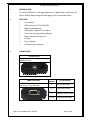
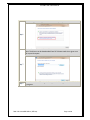
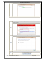
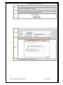
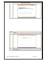
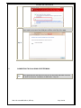
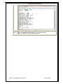
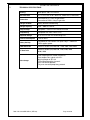
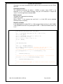
SS-68BB
USB MINI BUFFER
User Manual
SS-68BB USB USER MANUAL
Revision History
Revision 01
Revision 02
Revision 03
Revision 04
Revision 05
Original document
Cosmetic changes
Add Appendix A
Added Installation of USB drivers
Add reinstallation of USB drivers
2004
06 December 2007
10 December 2008
08 July 2011
21 February 2012
CONTENTS
1.
INTRODUCTION ...............................................................................................................3
2.
FEATURES .......................................................................................................................3
3.
CONNECTIONS ................................................................................................................3
4.
INSTALLATION OF USB WINDOWS 7 DRIVES ...............................................................4
5.
CONNECTING TO SS-68 USING HYPERTERMINAL .......................................................9
6.
PROGRAMMING INSTRUCTIONS ................................................................................. 12
7.
TECHNICAL SPECIFICATIONS ...................................................................................... 13
8.
CONTACT DETAILS ....................................................................................................... 14
APPENDIX A:
USING SS—68BB USB AS A SECURITY DONGLE .......................................... 15
DOC. NO: SS-68BB USB-14 (REV 05)
Page 2 of 16
SS-68BB USB USER MANUAL
1.
INTRODUCTION
The SS-68 USB Buffer is a call logging buffer that is supplied fitted standard with 128
Kbytes of RAM. Battery backup will allow logging in the event of power failure.
2.
3.
FEATURES
Line Powered
PABX connection OPTO-COUPLED
Battery backed operation
PABX power used when PC turned off
Full functionality during battery operation
Beeper warning when buffer full
Compact
Easy installation
LED buffer status indications
CONNECTIONS
PC Connection
USB PC Connection for programming and
collecting of data,
PABX Connection
PABX Connection is by means of a
male 9 way ‘D’ type connector
Pin
Number
2
Receive from PABX
4&7
Handshake to PABX
5
6&8
DOC. NO: SS-68BB USB-14 (REV 05)
Pin Description
Common ‘Ground’ signal
Handshake from PABX
Page 3 of 16
SS-68BB USB USER MANUAL
4.
INSTALLATION OF USB WINDOWS 7 DRIVES
SS-68BB Driver Installation
Step 1
Connect a USB cable between the PC and the SS-68 BB USB Device.
Step 2
Once the USB cable is connected, windows will try to install the driver.
When a window pops up that asks you if you would like to install the drivers go
to STEP 6, if not follow the next STEP.
If USB cable is plug into a second USB port, reinstall drivers. Go to STEP 6. Note
that it will install as a different COM port.
Note: UAC (User Account Control) must be disabled.
On the computer connected to the SS-68, Click on Start then right click on
“Computer ” and select “Manage”.
Step 3
Select “Device Manager” under Computer Management.
Step 4
Locate the SS-68 USB Databuffer under “Other devices” and right click and select
“Update Driver Software”
Step 5
DOC. NO: SS-68BB USB-14 (REV 05)
Page 4 of 16
SS-68BB USB USER MANUAL
The following window appears. Select “Browse my computer for drives”.
Step 6
Use the Browse button to locate drivers.
Note: The drivers can be downloaded from SS Telecoms web site or given on a
CD at special request.
Step 7
Step 8
Select Next and the following window appears indicating that the installation is
in progress.
DOC. NO: SS-68BB USB-14 (REV 05)
Page 5 of 16
SS-68BB USB USER MANUAL
When the Windows Security message pops up, choose “Install this driver
software anyway”.
Step 9
Once the USB driver is installed the following window appears.
Step 10
You will notice the SS Telecoms Data Buffer USB device under USB controllers.
Step 11
DOC. NO: SS-68BB USB-14 (REV 05)
Page 6 of 16
SS-68BB USB USER MANUAL
Once the USB device is installed, windows will try to install the USB serial driver.
Step 12 When a window pops up that asks you if you would like to install the drivers go
to STEP 15 if not follow the next STEP.
To get serial communication to the device you need to install the Serial to USB
driver. Locate the “USB Serial” under “Other devices”
Step 13
Right click and select “Update Driver Software”
Step 14
The following window appears. Select “Browse my computer for drives”.
Step 15
Step 15 Use the Browse button to locate drivers.
DOC. NO: SS-68BB USB-14 (REV 05)
Page 7 of 16
SS-68BB USB USER MANUAL
Step 16
Select Next and the following window appears indicating that the installation is
in progress.
Step 17
When the Windows Security message pops up, choose “Install this driver
software anyway”.
DOC. NO: SS-68BB USB-14 (REV 05)
Page 8 of 16
SS-68BB USB USER MANUAL
Once the USB driver is installed the following window appears.
Please make a not note of the COM port number at the top of the page.
Step 18
5.
CONNECTING TO SS-68 USING HYPERTERMINAL
Step 1
Open Hyperterminal and select the Com Port of the SS-68 USB Buffer and click
OK. Refer to Section 4 “Installation if USB Drivers “ Step 18
DOC. NO: SS-68BB USB-14 (REV 05)
Page 9 of 16
SS-68BB USB USER MANUAL
Select “Restore Defaults” then click OK
Step 2
STEP 3 When connected Hyperterminal will show “Connected” at the left bottom corner.
DOC. NO: SS-68BB USB-14 (REV 05)
Page 10 of 16
SS-68BB USB USER MANUAL
Once connected , you can start sending commands to the unit. Please see
STEP 4 Section 6 “Programming Instructions” for a list of commands.
Note: Use Upper Case when typing commands.
DOC. NO: SS-68BB USB-14 (REV 05)
Page 11 of 16
SS-68BB USB USER MANUAL
6.
PROGRAMMING INSTRUCTIONS
Instruction
Description
S<enter>
Request a record in ASCII
K<enter>
Request a compressed record
N<enter>
Advance record pointer. (Compressed mode only)
DMP<enter>
Dump all stored data
SC nn<enter>
Set Minimum Record Length. (Default = 0)
S7 n<enter>
SB nn<enter>
7 Bit operation if n = 1.
Note: use for 7 bit only operation, do not use for 7 bit
with parity.
Set PBX baud rate, where nn represents the first two
digits of the baud rate. Max 9600bps
SP nn<enter>
Set PC baud rate, where nn represents the first two
digits of the baud rate. Max 28800bps.
Note: The new settings will be operational after the
buffer is reset.
SD n<enter>
n=1 enable Date/Time insertion
n=0 disable Date/Time insertion
YY n<enter>
Store Year if n = 1
YC n<enter>
Store Century if n = 1 and n=1 for YY
T YYMMDDhhmm<enter>
Sets the Time
SA n<enter>
n = 1 Enable AutoDump; n = 0 Disable AutoDump
SAT nn<enter>
Set AutoDump timer to nn*100 milliseconds
CLR<enter>
Clear the memory and reset.
SYS<enter>
Display system information
HI<enter>
DR n<enter>
SQ n<enter>
Output Product Info, Maximum Memory Capacity,
Used Memory and number of lines used.
n = 1 Disable text on reset
n = 0 Enable text on reset
Enable sequence number storing if n=1
SH nn<enter>
nn = 00 Keep Handshaking on until the buffer is full.
(Rev 1.10 and above)
nn = 01 to 63 Normal operation were the cycle time
is 1 to 63 seconds with a 25% duty factor.
SAO nn<enter>
nn = AutoDump Auto Off Time in seconds
When set this will stop response to SA n commands and
it will cause the AutoDump mode to be cleared when the
handshaking has been off for more than the set time.
AutoDump then has to be re-enabled using SA 1.
V<enter>
Display Software Version number
TM<enter>
Do a memory test
DOC. NO: SS-68BB USB-14 (REV 05)
Page 12 of 16
SS-68BB USB USER MANUAL
7.
TECHNICAL SPECIFICATIONS
Housing
Black plastic 130 x 68 x 29 mm
LED indicators
PC Tx & Rx, 80% & 50% buffer full, PABX DATA, Heart beat
Connectors
Connection to PC: 9 way D-type female
Connection to PABX: 9 way D-type male
Storage medium
Battery backed RAM buffering
Storage capacity
128K - 4000 call records
Setup storage
Setup data is stored in non-volatile EEPROM
Compatibility
Compatible with most PABX’s units
Required voltage
5V to 12V DC from PC handshaking lines
Current consumption
5 mA to 10mA
Battery backup
3.6V 60mA Ni-Cad. Powers unit up to 2 days – Indefinite if
PABX supplies power
PABX baud rate
Software settable (Bd) 300, 600., 1200, 2400, 4800, 9600
PC baud rate
Software settable (Bd) 300, 600, 1200, 2400, 4800,
9600,19200
Data storage
Time stamping of call records and events
Data compression, typical ratio 2.5:1
Warning beeper at 95% full
DTR enabled dumping of records
ASCII handshake protocol
Fully error corrected proprietary protocol
DOC. NO: SS-68BB USB-14 (REV 05)
Page 13 of 16
SS-68BB USB USER MANUAL
8.
CONTACT DETAILS
Office:
23 Botha Avenue
Lyttelton Manor
Pretoria, Gauteng
South Africa
Tel:
Fax:
e-mail:
+27 12 664 4644
+27 86 614 5625
[email protected]
Postal address:
Postnet Suite 48
Private Bag x 1015
Lyttelton, 0140
Pretoria, Gauteng
South Africa
Sales Support:
e-mail: [email protected]
United Kingdom
e-mail: [email protected]
Technical Support:
e-mail: [email protected]
DOC. NO: SS-68BB USB-14 (REV 05)
Page 14 of 16
SS-68BB USB USER MANUAL
APPENDIX A:
USING SS—68BB USB AS A SECURITY DONGLE
INTRODUCTION
With the proliferation of software solutions it is becoming commonplace for software to be
pirated or used without authorisation.
A fairly standard solution is to provide a 'dongle' (hardware device) that attaches to the PC
and the software will not run if the device is not present. This obvious lock is often a
source of irritation to the end user.
A more elegant solution is to provide a 'useful' device that acts as the security dongle. The
data buffer is an obvious candidate for the task where a Telephone Management System
is the application.
SS Telecoms have developed a simple protocol that will allow software to verify that it is
attached to a matching buffer.
DISCUSSION ON SECURITY ISSUES
There is a simple level of security provided by having a data buffer in the first place.
Pitfalls can be identified such as
Another hardware manufacturer can develop a buffer with a similar protocol. This means
that it will be possible to hijack the software package by using these alternate buffers
Another software vendor can adapt his software to work with the buffers and thus take
over the installed base of buffers allowing this vendor a much cheaper entry to this
customer than the original vendor
Solution to issues
The basic solution to the problems outlined above has already needed addressing in the
GSM arena. Authentication of users is vital to ensure that billing is accurate, for example.
How do they do this? It is done using a system known as 'Challenge / Response'
authentication. This will be outlined briefly below.
Challenge Response Description
The PC software and the Buffer have both loaded with a secret key. This key can be up to
16 characters
The PC sends the buffer a challenge consisting of a short randomly generated message
of up to 10 characters.
The Buffer performs a 'hashing' function on this message using the secret key as part of
the process. It is not possible using a small number of messages to determine what the
key is.
The buffer then sends the result of the 'hashing' function to the PC.
The PC then compares this to the result of internally generating the 'hash' result
If the results match, then the buffer is authenticated and the software will run.
IMPLEMENTATION
Setting the key
Use the command '~ nnkk<enter>' where '~' is the tilde character, followed by a space
character and then the 2 digit hexadecimal offset ('nn') for the key character which is also
sent hexadecimal ('kk') and <enter> is the Carriage Return character 0x0D. The sequence
to set the secret code to 'TEST' is shown below:
~ 0054
~ 0145
~ 0253
~ 0354
DOC. NO: SS-68BB USB-14 (REV 05)
Page 15 of 16
SS-68BB USB USER MANUAL
The process has been automated and the code can be set and tested using the 'Buffer
Lock' tool.
Challenging the buffer
The command to challenge the buffer is: 'CODErrr..rrr<enter>' where 'CODE' is the
command, 'rrr..rrr' is the random challenge string up to 10 characters in length and
<enter> is the Carriage Return character 0x0D.
Buffer response
The buffer will respond with the following:
CODE: hhhh<enter>
Where 'CODE: ' is the response text and 'hhhh' is a 16 bit CRC for the submitted
challenge and the secret key.
Response validation
In the code below the variable CRC is a 16 bit unsigned integer and char is 8 bit. CmdBuf
is the input buffer where the string starting with 'CODE: ' is stored and CmdPtr indexes the
1st 'h'.
void CalcCrc(unsigned char
{
crc = (unsigned char)(crc
crc ^= ser_data;
crc ^= (unsigned char)(crc
crc ^= (crc << 8) << 4;
crc ^= ((crc & 0xff) << 4)
crc &= 0xFFFF;
}
ser_data)
>> 8) | (crc << 8);
& 0xff) >> 4;
<< 1;
void mfCode(void)
{
char * p = &CmdBuf[CmdPtr];
int retCrc = HexToInt(p,4); //convert the hex data to int
crc = 0xFFFF;
//initialise the crc
//======== do the calculation on the challenge =============
for (unsigned int i = 0; i < strlen(test); i++)
{
CalcCrc(test[i]);
}
//======== do the calculation on the UserKey
=============
for (int i = 0; i < strlen(SecretKey); i++)
{
CalcCrc(SecretKry[i]);
}
//==== crc should be equal to retCrc if all is well ==========
}
DOC. NO: SS-68BB USB-14 (REV 05)
Page 16 of 16