1
User’s Manual
32
RX64M Group
Renesas Starter Kit+ Code Generator Tutorial Manual
For CubeSuite+
RENESAS MCU
RX Family / RX600 Series
All information contained in these materials, including products and product specifications, represents
information on the product at the time of publication and is subject to change by Renesas Electronics
Corporation without notice. Please review the latest information published by Renesas Electronics
Corporation through various means, including the Renesas Electronics Corporation website
(http://www.renesas.com).
Rev. 1.00 Mar 2014
Notice
1.
Descriptions of circuits, software and other related information in this document are provided only to illustrate the
operation of semiconductor products and application examples. You are fully responsible for the incorporation of these
circuits, software, and information in the design of your equipment. Renesas Electronics assumes no responsibility for
any losses incurred by you or third parties arising from the use of these circuits, software, or information.
2. Renesas Electronics has used reasonable care in preparing the information included in this document, but Renesas
Electronics does not warrant that such information is error free. Renesas Electronics assumes no liability whatsoever
for any damages incurred by you resulting from errors in or omissions from the information included herein.
3. Renesas Electronics does not assume any liability for infringement of patents, copyrights, or other intellectual property
rights of third parties by or arising from the use of Renesas Electronics products or technical information described in
this document. No license, express, implied or otherwise, is granted hereby under any patents, copyrights or other
intellectual property rights of Renesas Electronics or others.
4. You should not alter, modify, copy, or otherwise misappropriate any Renesas Electronics product, whether in whole or
in part. Renesas Electronics assumes no responsibility for any losses incurred by you or third parties arising from such
alteration, modification, copy or otherwise misappropriation of Renesas Electronics product.
5. Renesas Electronics products are classified according to the following two quality grades: “Standard” and “High
Quality”. The recommended applications for each Renesas Electronics product depends on the product’s quality grade,
as indicated below.
“Standard”: Computers; office equipment; communications equipment; test and measurement equipment; audio
and visual equipment; home electronic appliances; machine tools; personal electronic equipment; and industrial
robots etc.
“High Quality”: Transportation equipment (automobiles, trains, ships, etc.); traffic control systems; anti-disaster
systems; anticrime systems; and safety equipment etc.
Renesas Electronics products are neither intended nor authorized for use in products or systems that may pose a
direct threat to human life or bodily injury (artificial life support devices or systems, surgical implantations etc.), or may
cause serious property damages (nuclear reactor control systems, military equipment etc.). You must check the quality
grade of each Renesas Electronics product before using it in a particular application. You may not use any Renesas
Electronics product for any application for which it is not intended. Renesas Electronics shall not be in any way liable
for any damages or losses incurred by you or third parties arising from the use of any Renesas Electronics product for
which the product is not intended by Renesas Electronics.
6. You should use the Renesas Electronics products described in this document within the range specified by Renesas
Electronics, especially with respect to the maximum rating, operating supply voltage range, movement power voltage
range, heat radiation characteristics, installation and other product characteristics. Renesas Electronics shall have no
liability for malfunctions or damages arising out of the use of Renesas Electronics products beyond such specified
ranges.
7. Although Renesas Electronics endeavors to improve the quality and reliability of its products, semiconductor products
have specific characteristics such as the occurrence of failure at a certain rate and malfunctions under certain use
conditions. Further, Renesas Electronics products are not subject to radiation resistance design. Please be sure to
implement safety measures to guard them against the possibility of physical injury, and injury or damage caused by fire
in the event of the failure of a Renesas Electronics product, such as safety design for hardware and software including
but not limited to redundancy, fire control and malfunction prevention, appropriate treatment for aging degradation or
any other appropriate measures. Because the evaluation of microcomputer software alone is very difficult, please
evaluate the safety of the final products or systems manufactured by you.
8. Please contact a Renesas Electronics sales office for details as to environmental matters such as the environmental
compatibility of each Renesas Electronics product. Please use Renesas Electronics products in compliance with all
applicable laws and regulations that regulate the inclusion or use of controlled substances, including without limitation,
the EU RoHS Directive. Renesas Electronics assumes no liability for damages or losses occurring as a result of your
noncompliance with applicable laws and regulations.
9. Renesas Electronics products and technology may not be used for or incorporated into any products or systems whose
manufacture, use, or sale is prohibited under any applicable domestic or foreign laws or regulations. You should not
use Renesas Electronics products or technology described in this document for any purpose relating to military
applications or use by the military, including but not limited to the development of weapons of mass destruction. When
exporting the Renesas Electronics products or technology described in this document, you should comply with the
applicable export control laws and regulations and follow the procedures required by such laws and regulations.
10. It is the responsibility of the buyer or distributor of Renesas Electronics products, who distributes, disposes of, or
otherwise places the product with a third party, to notify such third party in advance of the contents and conditions set
forth in this document, Renesas Electronics assumes no responsibility for any losses incurred by you or third parties as
a result of unauthorized use of Renesas Electronics products.
11. This document may not be reproduced or duplicated in any form, in whole or in part, without prior written consent of
Renesas Electronics.
12. Please contact a Renesas Electronics sales office if you have any questions regarding the information contained in this
document or Renesas Electronics products, or if you have any other inquiries.
(Note 1) “Renesas Electronics” as used in this document means Renesas Electronics Corporation and also includes its
majority owned subsidiaries.
(Note 2) “Renesas Electronics product(s)” means any product developed or manufactured by or for Renesas Electronics.
(2012.4)
Disclaimer
By using this Renesas Starter Kit+ (RSK+), the user accepts the following terms:
The RSK+ is not guaranteed to be error free, and the entire risk as to the results and performance of the RSK+ is
assumed by the User. The RSK+ is provided by Renesas on an “as is” basis without warranty of any kind whether
express or implied, including but not limited to the implied warranties of satisfactory quality, fitness for a particular
purpose, title and non-infringement of intellectual property rights with regard to the RSK+. Renesas expressly
disclaims all such warranties. Renesas or its affiliates shall in no event be liable for any loss of profit, loss of data,
loss of contract, loss of business, damage to reputation or goodwill, any economic loss, any reprogramming or recall
costs (whether the foregoing losses are direct or indirect) nor shall Renesas or its affiliates be liable for any other
direct or indirect special, incidental or consequential damages arising out of or in relation to the use of this RSK+,
even if Renesas or its affiliates have been advised of the possibility of such damages.
Precautions
The following precautions should be observed when operating any RSK+ product:
This Renesas Starter Kit+ is only intended for use in a laboratory environment under ambient temperature and
humidity conditions. A safe separation distance should be used between this and any sensitive equipment. Its use
outside the laboratory, classroom, study area or similar such area invalidates conformity with the protection
requirements of the Electromagnetic Compatibility Directive and could lead to prosecution.
The product generates, uses, and can radiate radio frequency energy and may cause harmful interference to radio
communications. However, there is no guarantee that interference will not occur in a particular installation. If this
equipment causes harmful interference to radio or television reception, which can be determined by turning the
equipment off or on, you are encouraged to try to correct the interference by one or more of the following measures;
•
ensure attached cables do not lie across the equipment
•
reorient the receiving antenna
•
increase the distance between the equipment and the receiver
•
connect the equipment into an outlet on a circuit different from that which the receiver is connected
•
power down the equipment when not in use
•
consult the dealer or an experienced radio/TV technician for help NOTE: It is recommended that wherever
possible shielded interface cables are used.
The product is potentially susceptible to certain EMC phenomena. To mitigate against them it is recommended that the
following measures be undertaken;
•
The user is advised that mobile phones should not be used within 10m of the product when in use.
•
The user is advised to take ESD precautions when handling the equipment.
The Renesas Starter Kit does not represent an ideal reference design for an end product and does not fulfil the
regulatory standards for an end product.
How to Use This Manual
1.
Purpose and Target Readers
This manual is designed to provide the user with an understanding of how to use Application Leading Tool
(Code Generator) for RX together with the CubeSuite+ IDE to create a working project for the RSK+ platform.
It is intended for users designing sample code on the RSK+ platform, using the many different incorporated
peripheral devices.
The manual comprises of step-by-step instructions to generate code and import it into CubeSuite+, but does
not intend to be a complete guide to software development on the RSK+ platform. Further details regarding
operating the RX64M microcontroller may be found in the Hardware Manual and within the provided sample
code.
Particular attention should be paid to the precautionary notes when using the manual. These notes occur within the body
of the text, at the end of each section, and in the Usage Notes section.
The revision history summarizes the locations of revisions and additions. It does not list all revisions. Refer to the text of
the manual for details.
The following documents apply to the RX64M Group. Make sure to refer to the latest versions of these
documents. The newest versions of the documents listed may be obtained from the Renesas Electronics Web
site.
Document Type
Description
Document Title
Document No.
User’s Manual
Describes the technical details of the RSK+
hardware.
RSK+RX64M User’s
Manual
R20UT2590EG
Tutorial
Provides a guide to setting up RSK+ environment,
running sample code and debugging programs.
RSK+RX64M
Tutorial Manual
R20UT2591EG
Quick Start Guide
Provides simple instructions to setup the RSK+ and
run the first sample.
RSK+RX64M Quick
Start Guide
R20UT2592EG
Code Generator
Tutorial
Provides a guide to code generation and importing
into the CubeSuite+ IDE.
RSK+RX64M Code
Generator Tutorial
Manual
R20UT2930EG
Schematics
Full detail circuit schematics of the RSK+.
RSK+RX64M
Schematics
R20UT2589EG
Hardware Manual
Provides technical
microcontroller.
RX600
Group
Hardware Manual
R01UH0377EJ
details
of
the
RX600
2.
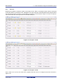
List of Abbreviations and Acronyms
Abbreviation
Full Form
ADC
Analog-to-Digital Converter
API
CMT
Application Programming Interface
Compare Match Timer
COM
CPU
COMmunications port referring to PC serial port
Central Processing Unit
DVD
E1
Digital Versatile Disc
On-chip Debugger
GUI
IDE
Graphical User Interface
Integrated Development Environment
IRQ
LCD
Interrupt Request line
Liquid Crystal Display
LED
MCU
Light Emitting Diode
Micro-controller Unit
MSB
PC
Most Significant Bit
Personal Computer
TM
Pmod
PLL
Digilent Pmod™ Compatible connector. PmodTM is registered
Digilent-Pmod_Interface_Specification (Link valid at 26Jun2013)
Phase-locked Loop
RSK+
SCI
Renesas Starter Kit Plus
Serial Communications Interface
SPI
UART
Serial Peripheral Interface
Universal Asynchronous Receiver/Transmitter
to
Digilent
Inc.
Table of Contents
1. Overview............................................................................................................................ 7
1.1
1.2
Purpose ...................................................................................................................................................... 7
Features ..................................................................................................................................................... 7
2. Introduction ........................................................................................................................ 8
3. Project Creation with CubeSuite+ ...................................................................................... 9
3.1
3.2
Introduction ................................................................................................................................................ 9
Creating the Project ................................................................................................................................... 9
4. Code Generation Using the CubeSuite+ plug in .............................................................. 11
4.1
4.2
4.3
Introduction .............................................................................................................................................. 11
Code Generator Tour ............................................................................................................................... 11
Code Generation ...................................................................................................................................... 13
5. Completing the Tutorial Project ........................................................................................ 26
5.1
5.2
5.3
5.4
5.5
5.6
5.7
Project Settings ........................................................................................................................................ 26
Additional Folders .................................................................................................................................... 28
LCD Code Integration .............................................................................................................................. 29
Switch Code Integration ........................................................................................................................... 32
Debug Code Integration ........................................................................................................................... 38
UART Code Integration ............................................................................................................................ 39
LED Code Integration .............................................................................................................................. 42
6. Debugging the Project ..................................................................................................... 44
7. Running the Code Generator Tutorial .............................................................................. 45
7.1
Running the Tutorial ................................................................................................................................. 45
8. Additional Information ...................................................................................................... 46
RSK+RX64M
RENESAS STARTER KIT
R20UT2930EG0100
Rev. 1.00
Jul 21, 2014
1. Overview
1.1
Purpose
This RSK+ is an evaluation tool for Renesas microcontrollers. This manual describes how to use the
CubeSuite+ IDE code generator plug in to create a working project for the RSK+ platform.
1.2
Features
This RSK+ provides an evaluation of the following features:
• Project Creation with CubeSuite+
•
Code Generation using the code generator plug in.
•
User circuitry such as switches, LEDs and a potentiometer
The RSK+ board contains all the circuitry required for microcontroller operation.
R20UT2930EG0100 Rev. 1.00
Jul 21, 2014
Page 7 of 50
RSK+RX64M
2. Introduction
2. Introduction
This manual is designed to answer, in tutorial form, how to use the code generator plug in for the RX family
together with the CubeSuite+ IDE to create a working project for the RSK+ platform. The tutorials help explain
the following:
•
Project generation using the CubeSuite+
•
Detailed use of the code generator plug in for CubeSuite+
•
Integration with custom code
•
Building the project CubeSuite+
The project generator will create a tutorial project with three selectable build configurations:
•
‘DefaultBuild’ is a project with debug support and optimisation level set to two.
•
‘Debug’ is a project built with the debugger support included. Optimisation is set to zero.
•
‘Release’ is a project with optimised compile options, producing code suitable for release in a product.
Some of the illustrative screenshots in this document will show text in the form RXxxx. These are general
screenshots and are applicable across the whole RX family. In this case, simply substitute RXxxx for RX64M
These tutorials are designed to show you how to use the RSK+ and are not intended as a comprehensive introduction to
the CubeSuite+ debugger, compiler toolchains or the E1 emulator. Please refer to the relevant user manuals for more indepth information.
R20UT2930EG0100 Rev. 1.00
Jul 21, 2014
Page 8 of 50
RSK+RX64M
4. Code Generation Using the CubeSuite+ plug in
3. Project Creation with CubeSuite+
3.1
Introduction
In this section the user will be guided through the steps required to create a new C project for the RX64M
MCU, ready to generate peripheral driver code using Code Generator. This project generation step is
necessary to create the MCU-specific project and debug files.
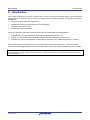
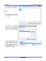
3.2
Creating the Project
•
Start Cubesuite+ by selecting it
from the Start Menu. Cubesuite+
will show the Start Page. Use the
‘GO’ button to create a new project
•
In the ‘Create Project’ dialog, select
‘RX’ from the ‘Microcontroller’ pulldown.
•
In the ‘Using Microcontroller’ list
control, scroll down to ‘RX64M’ and
expand the tree control by clicking
‘+’.
Select
‘R5F564MLCxFC(176pin)’.
•
Ensure that in the ‘Kind of project’
pull-down, ‘Empty Application(CCRX) is selected.
•
Choose an appropriate name and
location for the project, then click
‘Create’.
R20UT2930EG0100 Rev. 1.00
Jul 21, 2014
Page 9 of 50
RSK+RX64M
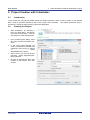
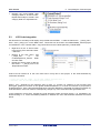
•
4. Code Generation Using the CubeSuite+ plug in
CubeSuite will create the project
files and a ‘Code Generator’ node
will be found in the left-hand
‘Project Tree’ window pane.
R20UT2930EG0100 Rev. 1.00
Jul 21, 2014
Page 10 of 50
RSK+RX64M
4. Code Generation Using the CubeSuite+ plug in
4.Code Generation Using the CubeSuite+ plug in
4.1
Introduction
TM
Code Generator is a Windows GUI tool for generating template ‘C’ source code and project settings for the
RX64M. When using Code Generator, the user is able to configure various MCU features and operating
parameters using intuitive GUI controls, thereby bypassing the need in most cases to refer to sections of the
Hardware Manual.
Once the user has configured the project, the ‘Generate Code’ function is used to generate three code
modules for each specific MCU feature selected. These code modules are name ‘r_cg_xxx.h’, ‘r_cg_xxx.c’,
and ‘r_cg_xxx_user.c’, where ‘xxx’ is a three letter acronym for the relevant MCU feature, for example ‘adc’.
Within these code modules, the user is then free to add custom code to meet their specific requirement.
Custom code should be added, whenever possible, in between the following comment delimiters:
/* Start user code for adding. Do not edit comment generated here */
/* End user code. Do not edit comment generated here */
Code Generator will locate these comment delimiters, and preserve any custom code inside the delimiters on
subsequent code generation operations. This is useful if, after adding custom code, the user needs to re-visit
Code Generator to change any MCU operating parameters.
By following the steps detailed in this Tutorial, the user will generate a Cubesuite+ project called CG_Tutorial.
The fully completed Tutorial project is contained on the DVD and may be imported into Cubesuite+ by
following the steps in the Quick Start Guide. This Tutorial is intended as a learning exercise for users who
wish to use the Code Generator to generate their own custom projects for Cubesuite+.
The CG_Tutorial project uses interrupts for switch inputs, the ADC module, the Compare Match Timer (CMT),
the Serial Communications Interface (SCI) and uses these modules to perform A/D conversion and display the
results via the Virtual COM port to a terminal program and also on the LCD display on the RSK+.
Following a tour of the key user interface features of Code Generator in §4.2, the reader is guided through
each of the peripheral function configuration dialogs in §4.3. In §5, the reader is familiarised with the structure
of the template code, as well as how to add their own code to the user code areas provided by the code
generator.
4.2
Code Generator Tour
In this section a brief tour of Code Generator is presented. For further details of the Code Generator
paradigm and reference, refer to the Application Leading Tool Common Operations manual
(r20ut2663ej0100_Code Generator.pdf). Application Leading Tool is the stand-alone version of Code
Generator and this manual is
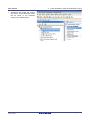
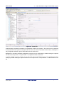
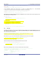
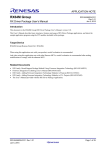
In the Project Tree pane, expand the ‘Code Generator’ node and double-click the ‘Peripheral Functions’ node.
The CubeSuite+ main window will now contain a ‘Peripheral Functions’ tab with the Initial View as show in
Figure 4-1.
R20UT2930EG0100 Rev. 1.00
Jul 21, 2014
Page 11 of 50
RSK+RX64M
4. Code Generation Using the CubeSuite+ plug in
Figure 4-1 Initial View
Code Generator provides GUI features for configuration of MCU sub systems. Once the user has configured
all required MCU sub systems and peripherals, the user can click the ‘Generate Code’ button, resulting in a
fully configured CubeSuite+ project that builds and runs without error.
Navigation to the MCU peripheral configuration screens may be performed by double-clicking the required
function in the Project Tree -> Project Name -> Peripheral Function on the left.
It is also possible to see a preview of the code that will be generated for the current peripheral function
settings by double-clicking the required function in the Project Tree -> Project Name -> Code Preview on the
left.
R20UT2930EG0100 Rev. 1.00
Jul 21, 2014
Page 12 of 50
RSK+RX64M
4.3
4. Code Generation Using the CubeSuite+ plug in
Code Generation
In the following sub-sections, the reader is guided through the steps to configure the MCU for a simple project
containing interrupts for switch inputs, timers, ADC and a UART.
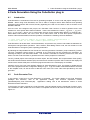
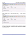
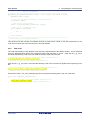
4.3.1
Clock Generator
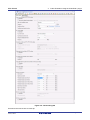
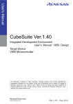
Figure 4-2 shows a screenshot of Code Generator with the Clock Generator function open. Click on the
‘Clock setting’ sub tab. Configure the system clocks as shown in the figure. In this tutorial we are using the
on board 24 MHz crystal resonator for our main clock oscillation source and the PLL circuit is in operation.
The PLL output is used as the main system clock and the divisors should be set as shown in Figure 4-2.
R20UT2930EG0100 Rev. 1.00
Jul 21, 2014
Page 13 of 50
RSK+RX64M
4. Code Generation Using the CubeSuite+ plug in
Figure 4-2 Clock setting tab
Proceed to the next section on Interrupt
R20UT2930EG0100 Rev. 1.00
Jul 21, 2014
Page 14 of 50
RSK+RX64M
4.3.1
4. Code Generation Using the CubeSuite+ plug in
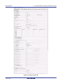
Interrupt Controller Unit
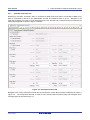
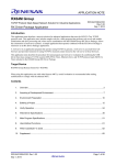
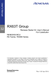
Referring to the RSK+ schematic, SW1 is connected to IRQ5 (P15) and SW2 is connected to IRQ2 (P12).
SW3 is connected to directly to the ADCTRG0n and will be configured later in §4.3.3. Navigate to the
‘Interrupt Controller Unit’ node in Code Generator and in the ‘General’ tab, configure these two interrupts as
falling edge triggered as shown in Figure 4-3 below.
Figure 4-3 Interrupt Functions tab
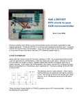
Navigate to the ‘Group Interrupts’ sub tab and ensure that the ‘Group BL0’ interrupt is selected as shown in
Figure 4-4. The Group BL0 interrupt is used for SCI Transmit End Interrupts (TEI) and Reception Error
Interrupts (ERI) as described in §4.3.4.
R20UT2930EG0100 Rev. 1.00
Jul 21, 2014
Page 15 of 50
RSK+RX64M
4. Code Generation Using the CubeSuite+ plug in
Figure 4-4 Group Interrupt Functions tab
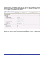
4.3.2
Compare Match Timer
Navigate to the ‘Compare Match Timer’ node in Code Generator. CMT0 will be used as an interval timer for
generation of accurate delays. CMT1 and CMT2 will be used as timers in de-bouncing of switch interrupts.
In the ‘CMT0’ sub-tab configure CMT0 as shown in Figure 4-5. This timer is configured to generate a High
priority interrupt every 1ms. We will use this interrupt later in the tutorial to provide an API for generating high
accuracy delays required in our application.
Figure 4-5 CMT0 tab
Navigate to the ‘CMT1’ sub-tab and configure CMT1 as shown in Figure 4-6. This timer is configured to
generate a High priority interrupt after 20ms. This timer is used as our short switch de-bounce timer later in
this tutorial.
R20UT2930EG0100 Rev. 1.00
Jul 21, 2014
Page 16 of 50
RSK+RX64M
4. Code Generation Using the CubeSuite+ plug in
Figure 4-6 CMT1 tab
Navigate to the ‘CMT2’ sub-tab and configure CMT2 as shown in Figure 4-7. This timer is configured to
generate a High priority interrupt after 200ms. This timer is used as our long switch de-bounce timer later in
this tutorial.
Figure 4-7 CMT2 tab
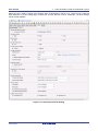
4.3.3
12-bit A/D Converter
Navigate to the ’12-bit A/D Converter’ tab in Code Generator. Refer to the screenshot shown in Figure 4-8
and configure the S12AD0 as shown. We will be using the S12AD0 in 12-bit one shot mode on the AN000
input, which is connected to the RV1 potentiometer output on the RSK+. The conversion start trigger will be
via the pin connected to SW3.
R20UT2930EG0100 Rev. 1.00
Jul 21, 2014
Page 17 of 50
RSK+RX64M
4. Code Generation Using the CubeSuite+ plug in
Figure 4-8 A/D Converter tab
R20UT2930EG0100 Rev. 1.00
Jul 21, 2014
Page 18 of 50
RSK+RX64M
4.3.4
4. Code Generation Using the CubeSuite+ plug in
Serial Communications Interface
Navigate to the ‘Serial Communications Interface’ tab in Code Generator, select the SCI6 sub-tab and apply
the settings shown in Figure 4-9. In the RSK+RX64M SCI6 is used as an SPI master for the Okaya PmodTM
LCD on the PMOD1 connector as shown in the schematic.
Figure 4-9 SCI6 General Setting tab
Select the SCI6 ‘Setting’ sub-tab and configure the SPI Master as illustrated in Figure 4-10. Make sure the
‘Transfer direction setting’ is set to ‘MSB-first’ and the ‘Bit rate’ is set to 1500000. All other settings remain at
their defaults.
R20UT2930EG0100 Rev. 1.00
Jul 21, 2014
Page 19 of 50
RSK+RX64M
4. Code Generation Using the CubeSuite+ plug in
Figure 4-10 SCI6 SPI Master Setting
Staying in the ‘Serial Communications Interface’ tab in Code Generator, select the SCI7 sub-tab and apply the
settings shown in Figure 4-11. In the RSK+RX64M SCI7 is connected via a Renesas RL78/G1C to provide a
USB virtual COM port as shown in the schematic.
Figure 4-11 SCI7 General Setting tab
R20UT2930EG0100 Rev. 1.00
Jul 21, 2014
Page 20 of 50
RSK+RX64M
4. Code Generation Using the CubeSuite+ plug in
Select the SCI7 ‘Setting’ sub-tab and configure SCI7 as illustrated in Figure 4-12. Make sure the ‘Start bit
edge detection’ is set as ‘Falling edge on RXD7 pin’ and the ‘Bit rate’ is set to 19200 bps. All other settings
remain at their defaults.
Figure 4-12 SCI7 Asynchronous Setting
R20UT2930EG0100 Rev. 1.00
Jul 21, 2014
Page 21 of 50
RSK+RX64M
4.3.5
4. Code Generation Using the CubeSuite+ plug in
I/O Ports
Referring to the RSK+ schematic, LED0 is connected to P03, LED1 is connected to P05, LED2 is connected
to P26 and LED3 is connected to P27. Navigate to the ‘I/O Ports’ tab in Code Generator and configure these
four I/O lines as shown in Figure 4-13 and Figure 4-14 below. Ensure that the ‘Output 1’ tick box is checked.
This ensures that the code is generated to set LEDs initially off.
Figure 4-13 I/O ports – Port0
Figure 4-14 I/O ports – Port2
P45 is used as one of the LCD control lines, together with P46 and P47. Configure these lines as shown in
Figure 4-15.
R20UT2930EG0100 Rev. 1.00
Jul 21, 2014
Page 22 of 50
RSK+RX64M
4. Code Generation Using the CubeSuite+ plug in
Figure 4-15 I/O ports – Port4
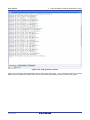
Peripheral function configuration is now complete. Save the project using the File -> Save Project menu item,
then click ‘Generate Code’. The Output pane should report ‘The operation of generating file was successful’,
as shown Figure 4-16 below.
R20UT2930EG0100 Rev. 1.00
Jul 21, 2014
Page 23 of 50
RSK+RX64M
4. Code Generation Using the CubeSuite+ plug in
Figure 4-16 Code generator console
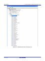
Figure 4-17 shows the Code Generator Files in the Project Tree pane. In the next section the CG_Tutorial
project will be completed by adding user code into these files and adding new source files to the project.
R20UT2930EG0100 Rev. 1.00
Jul 21, 2014
Page 24 of 50
RSK+RX64M
4. Code Generation Using the CubeSuite+ plug in
Figure 4-17 Code Generator Files in the Project Tree
R20UT2930EG0100 Rev. 1.00
Jul 21, 2014
Page 25 of 50
RSK+RX64M
5. Completing the Tutorial Project
5. Completing the Tutorial Project
5.1
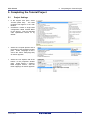
Project Settings
•
In the ‘Project Tree’ pane, select
‘CC-RX (Build Tool)’. The build
properties will appear in the main
window.
•
CubeSuite+ creates a single build
configuration called ‘Default Build’
for the project. This has standard
code optimisation turned on by
default.
•
Select the ‘Compile Options’ tab at
the bottom of the properties window
pane. Under ‘Language of the C
source file’ select ‘C99(-lang=c99)’
as shown opposite.
•
Select the ‘Link Options’ tab at the
bottom of the properties window
pane. Under ‘Section -> ROM to
RAM mapped section’, add the
three mappings as shown opposite.
.
R20UT2930EG0100 Rev. 1.00
Jul 21, 2014
Page 26 of 50
RSK+RX64M
•
5. Completing the Tutorial Project
These settings are easily added by
clicking the button ‘…’ and pasting
the following text into the dialog:
D=R
D_1=R_1
D_2=R_2
•
This ensures that the linker assigns
RAM rather than ROM addresses
to C variables.
•
From the ‘Build’ menu, select ‘Build
Mode Settings…’. Click ‘Duplicate’
and in the resulting ‘Character
String Input’ dialog, enter ‘Debug’
for the name of the duplicate build
mode.
•
The new ‘Debug’ build mode will be
added to the Build mode list. Click
‘Close’. Now, in the main CC-RX
under
the
Property
window,
‘Common Options’ tab, click on the
line containing ‘Build Mode’, click
the pull-down arrow and select
‘Debug’ from the pull-down’.
R20UT2930EG0100 Rev. 1.00
Jul 21, 2014
Page 27 of 50
RSK+RX64M
•
In the ‘Frequently Used Options (for
Compile)’
group,
select
the
‘Optimization Level’ option and
select ‘0’ from the pull-down. We
have now created a ‘Debug’ build
mode with no code optimisation
and will be using the Build mode to
create and debug the project.
•
All of the sample code projects
contained in this RSK are
configured with three Build modes;
‘DefaultBuild’,
‘Debug’
and
‘Release’. ‘Release’ is created in
the same way as above; by
duplicating
‘Default
Build’.
‘Release’ build mode leaves code
optimisation
turned
on
and
removes debug information from
the output file.
•
To remove debug information from
the ‘Release’ build mode, in the
‘CC-RX Property’ window, select
the ‘Common Options’ tab at the
bottom of the window pane. For
the ‘Outputs debugging information’
option, select ‘No(-nodebug).
•
Reset the build mode back to
‘Debug’ using the ‘Build Mode’ pulldown control.
•
From the menus, select ‘File ->
Save All’ to save all project
settings.
5.2
5. Completing the Tutorial Project
Additional Folders
•
Before new source files are added
to the project, we will create two
additional folders in the CubeSuite+
Project Tree.
•
In the Project Tree pane, right-click
the CG_Tutorial project and select
‘Add -> Add New Category’.
R20UT2930EG0100 Rev. 1.00
Jul 21, 2014
Page 28 of 50
RSK+RX64M
•
5.3
5. Completing the Tutorial Project
Rename the newly-created ‘New
Category’ folder to ‘C Source Files’.
Repeat these steps to create a new
category folder for ‘Dependencies’.
LCD Code Integration
API functions for the Okaya LCD display are provided with the RSK+. Locate the files ascii.h , r_okaya_lcd.h,
ascii.c, and r_okaya_lcd.c on the RSK+ DVD. These files can be found in the RSK+RX64M_Tutorial project
for CubeSuite+ in the ‘Tutorial’ folder. Copy these files into the C:\Workspace\CG_Tutorial folder.
•
Right-click on the ‘C Source Files’
in the Project Tree and select ‘Add > Add File…’.
•
Browse to the files ascii.c, and
in
the
r_okaya_lcd.c
C:\Workspace\CG_Tutorial folder
and click ‘Add’.
•
Repeat the above steps to add the
files ascii.h , r_okaya_lcd.h to the
‘Dependencies’ folder.
Code must be inserted in to the user code area in many files in this project, in the areas delimited by
comments as follows:
/* Start user code for _xxxxx_. Do not edit comment generated here */
/* End user code. Do not edit comment generated here */
Where _xxxx_ depends on the particular area of code, i.e. ‘function’ for insertion of user functions and
prototypes, ‘global’ for insertion of user global variable declarations, or ‘include’ for insertion of pre-processor
include directives. User code inserted inside these comment delimiters is protected from being overwritten by
Code Generator, if the user needs to subsequently change any of the Code Generator-generated code.
In the Cubesuite+ Project Tree, expand the ‘Code Generator’ folder and open the file ‘r_cg_userdefine.h’ by
double-clicking on it. Insert the following #defines in between the user code delimiter comments as shown
below.
R20UT2930EG0100 Rev. 1.00
Jul 21, 2014
Page 29 of 50
RSK+RX64M
5. Completing the Tutorial Project
/* Start user code for global. Do not edit comment generated here */
#define TRUE
(1)
#define FALSE
(0)
/* End user code. Do not edit comment generated here */
In the Cubesuite+ Project Tree, open the file ‘r_cg_main.c’ by double-clicking on it.
"r_okaya_lcd.h" in between the user code delimiter comments as shown below.
Insert #include
/* Start user code for include. Do not edit comment generated here */
#include "r_okaya_lcd.h"
/* End user code. Do not edit comment generated here */
Scroll down to the ‘main()’ function and insert the highlighted code as shown below into the beginning of the
user code area of the main() function:
void main(void)
{
R_MAIN_UserInit();
/* Start user code. Do not edit comment generated here */
/* Initialise the debug LCD */
R_LCD_Init();
/* Displays the application name on the debug LCD */
R_LCD_Display(0, (uint8_t *)" RSK+RX64M ");
R_LCD_Display(1, (uint8_t *)" Tutorial ");
R_LCD_Display(2, (uint8_t *)" Press Any Switch ");
while (1U)
{
;
}
/* End user code. Do not edit comment generated here */
}
5.3.1
SPI Code
The Okaya LCD display is driven by the SPI Master that was configured using Code Generator in §4.3.4. In
the Cubesuite+ Project Tree, open the file ‘r_cg_sci.h’ by double-clicking on it. Insert the following code in the
user code area at the end of the file:
/* Start user code for function. Do not edit comment generated here */
MD_STATUS R_SCI6_SPIMasterTransmit(uint8_t * const tx_buf, const uint16_t tx_num);
/* End user code. Do not edit comment generated here */
Now, open the r_cg_sci_user.c file and insert the following code in the user area for global:
/* Start user code for global. Do not edit comment generated here */
/* Flag used locally to detect transmission complete */
static volatile uint8_t sci6_txdone;
/* End user code. Do not edit comment generated here */
Insert the following code in the transmitend call-back function for SCI6:
static void r_sci6_callback_transmitend(void)
{
/* Start user code. Do not edit comment generated here */
sci6_txdone = TRUE;
/* End user code. Do not edit comment generated here */
}
Now insert the following function in the user code area at the end of the file:
/********************************************************************************
* Function Name: R_SCI6_SPIMasterTransmit
* Description : This function sends SPI6 data to slave device.
* Arguments
: tx_buf *
transfer buffer pointer
*
tx_num *
buffer size
* Return Value : status -
R20UT2930EG0100 Rev. 1.00
Jul 21, 2014
Page 30 of 50
RSK+RX64M
5. Completing the Tutorial Project
*
MD_OK or MD_ARGERROR
*********************************************************************************/
MD_STATUS R_SCI6_SPIMasterTransmit (uint8_t * const tx_buf, const uint16_t tx_num)
{
MD_STATUS status = MD_OK;
/* clear the flag before initiating a new transmission */
sci6_txdone = FALSE;
/* Send the data using the API */
status = R_SCI6_SPI_Master_Send(tx_buf, tx_num);
/* Wait for the transmit end flag */
while (FALSE == sci6_txdone)
{
/* Wait */
}
return (status);
}
/*********************************************************************************
* End of function R_SCI6_SPIMasterTransmit
**********************************************************************************/
This function uses the transmit end callback function to perform flow control on the SPI transmission to the
LCD, and is used as the main API call in the LCD code module.
5.3.2
CMT Code
The LCD code needs to insert delays to meet the timing requirements of the display module. This is achieved
using the dedicated timer which was configured using Code Generator in §4.3.2. Open the file r_cg_cmt.h
and insert the following code in the user area for function at the end of the file:
/* Start user code for function. Do not edit comment generated here */
void R_CMT_MsDelay(const uint16_t millisec);
/* End user code. Do not edit comment generated here */
Open the file r_cg_cmt_user.c and insert the following code in the user area for global at the beginning of the
file:
/* Start user code for global. Do not edit comment generated here */
static volatile uint8_t one_ms_delay_complete = FALSE;
/* End user code. Do not edit comment generated here */
Scroll down to the r_cmt_cmi0_interrupt() function and insert the following line in the user code area:
static void r_cmt_cmi0_interrupt(void)
{
/* Start user code. Do not edit comment generated here */
one_ms_delay_complete = TRUE;
/* End user code. Do not edit comment generated here */
}
R20UT2930EG0100 Rev. 1.00
Jul 21, 2014
Page 31 of 50
RSK+RX64M
5. Completing the Tutorial Project
Then insert the following function in the user code area at the end of the file:
/*******************************************************************************
* Function Name: R_CMT_MsDelay
* Description : Uses CMT0 to wait for a specified number of milliseconds
* Arguments
: uint16_t millisecs, number of milliseconds to wait
* Return Value : None
*******************************************************************************/
void R_CMT_MsDelay (const uint16_t millisec)
{
uint16_t ms_count = 0;
do
{
R_CMT0_Start();
while (FALSE == one_ms_delay_complete)
{
/* Wait */
}
R_CMT0_Stop();
one_ms_delay_complete = FALSE;
ms_count++;
} while (ms_count < millisec);
}
/*******************************************************************************
End of function R_CMT_MsDelay
*******************************************************************************/
Select ‘Build Project’ from the ‘Build’ menu, or press F7. Cubesuite+ will build the project with no errors.
The project may now be run using the debugger as described in §6. The program will display ‘RSK+X64M
Tutorial Press Any Switch on 3 lines in the LCD display.
5.4
Switch Code Integration
API functions for user switch control are provided with the RSK+. Locate the files rskrx64def.h, r_rsk_switch.h
and r_rsk_switch.c on the RSK+ DVD. RSK+RX64M_Tutorial project for CubeSuite+ in the ‘Tutorial’ folder.
Copy these files into the C:\Workspace\CG_Tutorial folder. Import these two files into the project in the same
way as the lcd files.
The switch code uses interrupt code in the files r_cg_icu.h, r_cg_icu.c and r_cg_icu_user.c and timer code in
the files r_cg_cmt.h, r_cg_cmt.c and r_cg_cmt_user.c, as described in §4.3.1 and §4.3.2. It is necessary to
provide additional user code in these files to implement the switch press/release detection and de-bouncing
required by the API functions in r_rsk_switch.c.
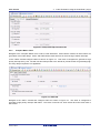
5.4.1
Interrupt Code
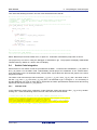
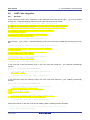
In the Cubesuite+ Project Tree, expand the ‘Code Generator’ folder and open the file ‘r_cg_icu.h’ by doubleclicking on it. Insert the following code in the user code area at the end of the file:
/* Start user code for function. Do not edit comment generated here */
/* Function prototypes for detecting and setting the edge trigger of ICU_IRQ */
uint8_t R_ICU_IRQIsFallingEdge(const uint8_t irq_no);
void R_ICU_IRQSetFallingEdge(const uint8_t irq_no, const uint8_t set_f_edge);
void R_ICU_IRQSetRisingEdge(const uint8_t irq_no, const uint8_t set_r_edge);
/* End user code. Do not edit comment generated here */
R20UT2930EG0100 Rev. 1.00
Jul 21, 2014
Page 32 of 50
RSK+RX64M
5. Completing the Tutorial Project
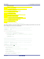
Now, open the r_cg_icu.c file and insert the following code in the user code area at the end of the file:
/*******************************************************************************
* Function Name: R_ICU_IRQIsFallingEdge
* Description : This function returns 1 if the specified ICU_IRQ is set to
*
falling edge triggered, otherwise 0.
* Arguments
: uint8_t irq_no
* Return Value : 1 if falling edge triggered, 0 if not
*******************************************************************************/
uint8_t R_ICU_IRQIsFallingEdge (const uint8_t irq_no)
{
uint8_t falling_edge_trig = 0x0;
if (ICU.IRQCR[irq_no].BYTE & _04_ICU_IRQ_EDGE_FALLING)
{
falling_edge_trig = 1;
}
return falling_edge_trig;
}
/*******************************************************************************
* End of function R_ICU_IRQIsFallingEdge
*******************************************************************************/
/*******************************************************************************
* Function Name: R_ICU_IRQSetFallingEdge
* Description : This function sets/clears the falling edge trigger for the
*
specified ICU_IRQ.
* Arguments
: uint8_t irq_no
*
uint8_t set_f_edge, 1 if setting falling edge triggered, 0 if
*
clearing
* Return Value : None
*******************************************************************************/
void R_ICU_IRQSetFallingEdge (const uint8_t irq_no, const uint8_t set_f_edge)
{
if (1 == set_f_edge)
{
ICU.IRQCR[irq_no].BYTE |= _04_ICU_IRQ_EDGE_FALLING;
}
else
{
ICU.IRQCR[irq_no].BYTE &= (uint8_t) ~_04_ICU_IRQ_EDGE_FALLING;
}
}
/******************************************************************************
* End of function R_ICU_IRQSetFallingEdge
*******************************************************************************/
/*******************************************************************************
* Function Name: R_ICU_IRQSetRisingEdge
* Description : This function sets/clear the rising edge trigger for the
*
specified ICU_IRQ.
* Arguments
: uint8_t irq_no
*
uint8_t set_r_edge, 1 if setting rising edge triggered, 0 if
*
clearing
* Return Value : None
*******************************************************************************/
void R_ICU_IRQSetRisingEdge (const uint8_t irq_no, const uint8_t set_r_edge)
{
if (1 == set_r_edge)
{
ICU.IRQCR[irq_no].BYTE |= _08_ICU_IRQ_EDGE_RISING;
}
else
{
ICU.IRQCR[irq_no].BYTE &= (uint8_t) ~_08_ICU_IRQ_EDGE_RISING;
}
}
/******************************************************************************
* End of function R_ICU_IRQSetRisingEdge
*******************************************************************************/
R20UT2930EG0100 Rev. 1.00
Jul 21, 2014
Page 33 of 50
RSK+RX64M
5. Completing the Tutorial Project
Open the r_cg_intp_user file.c file and insert the following code in the user code area for include near the top
of the file:
/* Defines switch callback functions required by interrupt handlers */
#include "r_rsk_switch.h"
In the same file insert the following code in the user code area inside the function r_icu_irq2_interrupt ():
/* Switch 2 callback handler */
R_SWITCH_IsrCallback2();
In the same file insert the following code in the user code area inside the function r_icu_irq5_interrupt ():
/* Switch 1 callback handler */
R_SWITCH_IsrCallback1();
5.4.2
De-bounce Timer Code
Open the r_cg_cmt_user.c file and insert the following code in the user code area for include near the top of
the file:
/* Defines switch callback functions required by interrupt handlers */
#include "r_rsk_switch.h"
In the same file insert the following code in the user code area inside the function r_cmt_cmi1_interrupt ():
/* Stop this timer - we start it again in the de-bounce routines */
R_CMT1_Stop();
/* Call the de-bounce call back routine */
R_SWITCH_DebounceIsrCallback();
In the same file insert the following code in the user code area inside the function r_cmt_cmi2_interrupt ():
/* Stop this timer - we start it again in the de-bounce routines */
R_CMT2_Stop();
/* Call the de-bounce call back routine */
R_SWITCH_DebounceIsrCallback();
5.4.3
Main Switch and ADC Code
In this part of the tutorial we add the code to act on the switch presses to activate A/D conversions and display
the result on the LCD. In §4.3.3 we configured the ADC to be triggered from the ADTRG0# pin. In this code,
we also perform software triggered A/D conversion from the user switches SW1 and SW2, by reconfiguring
the ADC trigger source on-the-fly once an SW1 or SW2 press is detected.
In the Cubesuite+ Project Tree, expand the ‘Code Generator’ folder and open the file ‘r_cg_userdefine.h’ by
double-clicking on it. Insert the following code the user code area, resulting in the code shown below
/* Start user code for function. Do not edit comment generated here */
#define TRUE
(1)
#define FALSE
(0)
extern volatile uint8_t g_adc_trigger;
/* End user code. Do not edit comment generated here */
Open the file ‘r_cg_main.c’ and insert #include "r_rsk_switch.h" in the user code area for include, resulting in
the code shown below:
/* Start user code for include. Do not edit comment generated here */
#include "r_okaya_lcd.h"
#include "r_rsk_switch.h"
R20UT2930EG0100 Rev. 1.00
Jul 21, 2014
Page 34 of 50
RSK+RX64M
5. Completing the Tutorial Project
/* End user code. Do not edit comment generated here */
Next add the switch module initialisation function call highlighted in the user code area inside the main()
function, resulting in the code shown below:
void main(void)
{
R_MAIN_UserInit();
/* Start user code. Do not edit comment generated here */
/* Initialise the switch module */
R_SWITCH_Init();
/* Initialise the debug LCD */
R_LCD_Init();
/* Displays the application name on the debug LCD */
R_LCD_Display(0, (uint8_t *)" RSK+RX64M ");
R_LCD_Display(1, (uint8_t *)" Tutorial ");
R_LCD_Display(2, (uint8_t *)" Press Any Switch ");
while (1U)
{
;
}
/* End user code. Do not edit comment generated here */
}
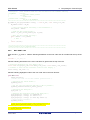
In the same file, insert the declarations in the user code area for global, resulting in the code shown below:
/* Start user code for global. Do not edit comment generated here */
/* Prototype declaration for cb_switch_press */
static void cb_switch_press (void);
/* Prototype declaration for get_adc */
static uint16_t get_adc(void);
/* Prototype declaration for lcd_display_adc */
static void lcd_display_adc (const uint16_t adc_result);
/* Variable for flagging user requested ADC conversion */
volatile uint8_t g_adc_trigger = FALSE;
/* End user code. Do not edit comment generated here */
Next add the highlighted code below in the user code area inside the main() function and the code inside the
while loop, resulting in the code shown below:
void main(void)
{
R_MAIN_UserInit();
/* Start user code. Do not edit comment generated here */
/* Initialise the switch module */
R_SWITCH_Init();
/* Set the call back function when SW1 or SW2 is pressed */
R_SWITCH_SetPressCallback(cb_switch_press);
/* Initialise the debug LCD */
R_LCD_Init ();
/* Displays the application name on the debug LCD */
R_LCD_Display(0, (uint8_t *)" RSK+RX64M ");
R_LCD_Display(1, (uint8_t *)" Tutorial ");
R_LCD_Display(2, (uint8_t *)" Press Any Switch ");
/* Start the A/D converter */
R_S12AD0_Start();
while (1U)
{
R20UT2930EG0100 Rev. 1.00
Jul 21, 2014
Page 35 of 50
RSK+RX64M
5. Completing the Tutorial Project
uint16_t adc_result;
/* Wait for user requested A/D conversion flag to be set (SW1 or SW2) */
if (TRUE == g_adc_trigger)
{
/* Call the function to perform an A/D conversion */
adc_result = get_adc();
/* Display the result on the LCD */
lcd_display_adc(adc_result);
/* Reset the flag */
g_adc_trigger = FALSE;
}
/* SW3 is directly wired into the ADTRG0n pin so will
cause the interrupt to fire */
else if (TRUE == g_adc_complete)
{
/* Get the result of the A/D conversion */
R_S12AD0_Get_ValueResult(ADCHANNEL0, &adc_result);
/* Display the result on the LCD */
lcd_display_adc(adc_result);
/* Reset the flag */
g_adc_complete = FALSE;
}
}
/* End user code. Do not edit comment generated here */
}
Then add the definition for the switch call-back, get_adc() and lcd_display_adc() functions in the user code
area for adding at the end of the file, as shown below:
/******************************************************************************
* Function Name : cb_switch_press
* Description
: Switch press callback function. Sets g_adc_trigger flag.
* Argument
: none
* Return value : none
******************************************************************************/
static void cb_switch_press (void)
{
/* Check if switch 1 or 2 was pressed */
if (g_switch_flag & (SWITCHPRESS_1 | SWITCHPRESS_2))
{
/* set the flag indicating a user requested A/D conversion is required */
g_adc_trigger = TRUE;
/* Clear flag */
g_switch_flag = 0x0;
}
}
/******************************************************************************
* End of function cb_switch_press
******************************************************************************/
/******************************************************************************
* Function Name : get_adc
* Description
: Reads the ADC result, converts it to a string and displays
*
it on the LCD panel.
* Argument
: none
* Return value : uint16_t adc value
******************************************************************************/
static uint16_t get_adc (void)
{
/* A variable to retrieve the adc result */
uint16_t adc_result;
/* Stop the A/D converter being triggered from the pin ADTRG0n
R_S12AD0_Stop();
*/
/* Start a conversion */
R_S12AD0_SWTriggerStart();
/* Wait for the A/D conversion to complete */
while (FALSE == g_adc_complete)
{
R20UT2930EG0100 Rev. 1.00
Jul 21, 2014
Page 36 of 50
RSK+RX64M
5. Completing the Tutorial Project
/* Wait */
}
/* Stop conversion */
R_S12AD0_SWTriggerStop();
/* Clear ADC flag */
g_adc_complete = FALSE;
R_S12AD0_Get_ValueResult(ADCHANNEL0, &adc_result);
/* Set AD conversion start trigger source back to ADTRG0n pin */
R_S12AD0_Start();
return adc_result;
}
/******************************************************************************
* End of function get_adc
******************************************************************************/
/******************************************************************************
* Function Name : lcd_display_adc
* Description
: Converts adc result to a string and displays
*
it on the LCD panel.
* Argument
: uint16_t adc result
* Return value : none
******************************************************************************/
static void lcd_display_adc (const uint16_t adc_result)
{
/* Declare a temporary variable */
uint8_t a;
/* Declare temporary character string */
char
lcd_buffer[11] = " ADC: XXXH";
/* Convert ADC result into a character string,
Casting to ensure use of correct data type.
a = (uint8_t)((adc_result & 0x0F00) >> 8);
lcd_buffer[6] = (char)((a < 0x0A) ? (a + 0x30)
a = (uint8_t)((adc_result & 0x00F0) >> 4);
lcd_buffer[7] = (char)((a < 0x0A) ? (a + 0x30)
a = (uint8_t)(adc_result & 0x000F);
lcd_buffer[8] = (char)((a < 0x0A) ? (a + 0x30)
and store in the local.
*/
: (a + 0x37));
: (a + 0x37));
: (a + 0x37));
/* Display the contents of the local string lcd_buffer */
R_LCD_Display(3, (uint8_t *)lcd_buffer);
}
/******************************************************************************
* End of function lcd_display_adc
******************************************************************************/
Open the file ‘r_cg_s12ad.h’ by double-clicking on it. Insert the following code in the in the user code area for
function, resulting in the code shown below:
/* Start user code for function. Do not edit comment generated here */
/* Flag indicates when A/D conversion is complete */
extern volatile uint8_t g_adc_complete;
/* Functions for starting and stopping software triggered A/D conversion */
void R_S12AD0_SWTriggerStart(void);
void R_S12AD0_SWTriggerStop(void);
/* End user code. Do not edit comment generated here */
Open the file ‘r_cg_s12ad.c’ by double-clicking on it. Insert the following code in the in the user code area for
adding at the end of the file, resulting in the code shown below:
/* Start user code for adding. Do not edit comment generated here */
/*******************************************************************************
* Function Name: R_S12AD0_SWTriggerStart
* Description : This function starts the AD0 converter.
* Arguments
: None
R20UT2930EG0100 Rev. 1.00
Jul 21, 2014
Page 37 of 50
RSK+RX64M
5. Completing the Tutorial Project
* Return Value : None
*******************************************************************************/
void R_S12AD0_SWTriggerStart(void)
{
IR(PERIB, INTB129) = 0U;
IEN(PERIB, INTB129) = 1U;
ICU.GENBL1.BIT.EN19 = 1U;
S12AD.ADCSR.BIT.ADST = 1U;
}
/*******************************************************************************
End of function R_S12AD0_SWTriggerStart
*******************************************************************************/
/*******************************************************************************
* Function Name: R_S12AD0_SWTriggerStop
* Description : This function stops the AD0 converter.
* Arguments
: None
* Return Value : None
*******************************************************************************/
void R_S12AD0_SWTriggerStop(void)
{
S12AD.ADCSR.BIT.ADST = 0U;
IEN(PERIB, INTB129) = 0U;
IR(PERIB, INTB129) = 0U;
ICU.GENBL1.BIT.EN19 = 0U;
}
/*******************************************************************************
End of function R_S12AD0_SWTriggerStop
*******************************************************************************/
/* End user code. Do not edit comment generated here */
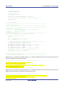
Open the file r_cg_s12ad_user.c and insert the following code in the in the user code area for global, resulting
in the code shown below:
/* Start user code for global. Do not edit comment generated here */
/* Flag indicates when A/D conversion is complete */
volatile uint8_t g_adc_complete;
/* End user code. Do not edit comment generated here */
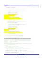
Insert the following code in the in the user code area of the r_s12ad0_interrupt () function, resulting in the
code shown below:
static void r_s12ad0_interrupt(void)
{
/* Start user code. Do not edit comment generated here */
g_adc_complete = TRUE;
/* End user code. Do not edit comment generated here */
}
Select ‘Build Project’ from the ‘Build’ menu, or press F7. Cubesuite+ will build the project with no errors.
The project may now be run using the debugger as described in §6. When any switch is pressed, the
program will perform an A/D conversion of the voltage level on the ADPOT line and display the result on the
LCD panel. Return to this point in the Tutorial to add the UART user code.
5.5
Debug Code Integration
API functions for trace debugging via the RSK serial port are provided with the RSK. Locate the files
r_rsk_debug.h and r_rsk_debug.c on the RSK DVD. RSK+RX64M_Tutorial project for CubeSuite+ in the
‘Tutorial’ folder. Copy these files into the C:\Workspace\CG_Tutorial folder. Import these two files into the
project in the same way as the LCD files.
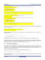
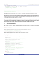
In the r_rsk_debug.h file, ensure the following macro definition is included:
/* Macro for definition of serial debug transmit function - user edits this */
#define SerialDbgWrite (R_SCI7_AsyncTransmit)
This macro is referenced in the r_rsk_debug.c file and allows easy re-direction of debug output if a different
debug interface is used.
R20UT2930EG0100 Rev. 1.00
Jul 21, 2014
Page 38 of 50
RSK+RX64M
5.6
UART Code Integration
5.6.1
SCI Code
5. Completing the Tutorial Project
In the Cubesuite+ Project Tree, expand the ‘Code Generator’ folder and open the file ‘r_cg_sci.h’ by doubleclicking on it. Insert the following code in the user code area at the end of the file:
/* Start user code for function. Do not edit comment generated here */
/* Exported functions used to transmit a number of bytes and wait for completion */
MD_STATUS R_SCI6_SPIMasterTransmit(uint8_t * const tx_buf, const uint16_t tx_num);
MD_STATUS R_SCI7_AsyncTransmit(uint8_t * const tx_buf, const uint16_t tx_num);
/* Character is used to receive key presses from PC terminal */
extern uint8_t g_rx_char;
/* Flag used to control transmission to PC terminal */
extern volatile uint8_t g_tx_flag;
/* End user code. Do not edit comment generated here */
Open the file ‘r_cg_sci_user.c. Insert the following code in the user area for global near the beginning of the
file:
/* Start user code for global. Do not edit comment generated here */
/* Global used to receive a character from the PC terminal */
uint8_t g_rx_char;
/* Flag used to control transmission to PC terminal */
volatile uint8_t g_tx_flag = FALSE;
/* Flag used locally to detect transmission complete */
static volatile uint8_t sci6_txdone;
static volatile uint8_t sci7_txdone;
/* End user code. Do not edit comment generated here */
In the same file, insert the following code in the user code area inside the r_sci7_callback_transmitend()
function:
static void r_sci7_callback_transmitend(void)
{
/* Start user code. Do not edit comment generated here */
sci7_txdone = TRUE;
/* End user code. Do not edit comment generated here */
}
In the same file, insert the following code in the user code area inside the r_sci7_callback_receiveend()
function:
static
{
/*
/*
if
{
void r_sci7_callback_receiveend(void)
Start user code. Do not edit comment generated here */
Check the contents of g_rx_char */
(('c' == g_rx_char) || ('C' == g_rx_char))
g_adc_trigger = TRUE;
}
/* Set up SCI7 receive buffer and callback function again */
R_SCI7_Serial_Receive((uint8_t *)&g_rx_char, 1);
/* End user code. Do not edit comment generated here */
}
At the end of the file, in the user code area for adding, add the following function definition:
/*******************************************************************************
* Function Name: R_SCI7_AsyncTransmit
R20UT2930EG0100 Rev. 1.00
Jul 21, 2014
Page 39 of 50
RSK+RX64M
5. Completing the Tutorial Project
* Description : This function sends SCI7 data and waits for the transmit end flag.
* Arguments
: tx_buf *
transfer buffer pointer
*
tx_num *
buffer size
* Return Value : status *
MD_OK or MD_ARGERROR
*******************************************************************************/
MD_STATUS R_SCI7_AsyncTransmit (uint8_t * const tx_buf, const uint16_t tx_num)
{
MD_STATUS status = MD_OK;
/* clear the flag before initiating a new transmission */
sci7_txdone = FALSE;
/* Send the data using the API */
status = R_SCI7_Serial_Send(tx_buf, tx_num);
/* Wait for the transmit end flag */
while (FALSE == sci7_txdone)
{
/* Wait */
}
return (status);
}
/*******************************************************************************
* End of function R_SCI7_AsyncTransmit
*******************************************************************************/
5.6.2
Main UART code
Open the file ‘r_cg_main.c’. Add the following declaration to the user code area for include near the top of the
file:
#include "r_rsk_debug.h"
Add the following declaration to the user code area for global near the top of the file:
/* Prototype declaration for uart_display_adc */
static void uart_display_adc(const uint8_t adc_count, const uint16_t adc_result);
/* Variable to store the A/D conversion count for user display */
static uint8_t adc_count = 0;
Add the following highlighted code to the user code area in the main function:
void main(void)
{
R_MAIN_UserInit();
/* Start user code. Do not edit comment generated here */
/* Initialise the switch module */
R_SWITCH_Init();
/* Set the call back function when SW1 or SW2 is pressed */
R_SWITCH_SetPressCallback(cb_switch_press);
/* Initialise the debug LCD */
R_LCD_Init ();
/* Displays the application name on the debug LCD */
R_LCD_Display(0, (uint8_t *)" RSK+RX64M ");
R_LCD_Display(1, (uint8_t *)" Tutorial ");
R_LCD_Display(2, (uint8_t *)" Press Any Switch ");
/* Start the A/D converter */
R_S12AD0_Start();
/* Set up SCI7 receive buffer and callback function */
R_SCI7_Serial_Receive((uint8_t *)&g_rx_char, 1);
/* Enable SCI7 operations */
R_SCI7_Start();
R20UT2930EG0100 Rev. 1.00
Jul 21, 2014
Page 40 of 50
RSK+RX64M
5. Completing the Tutorial Project
while (1U)
{
/* Wait for user requested A/D conversion flag to be set */
if (TRUE == g_adc_trigger)
{
uint16_t adc_result;
/* Call the function to perform an A/D conversion
adc_result = get_adc();
*/
/* Display the result on the LCD */
lcd_display_adc(adc_result);
/* Increment the adc_count */
if (16 == ++adc_count)
{
adc_count = 0;
}
/* Send the result to the UART */
uart_display_adc(adc_count, adc_result);
/* Reset the flag */
g_adc_trigger = FALSE;
}
/* SW3 is directly wired into the ADTRG0n pin so will
cause the interrupt to fire */
else if (TRUE == g_adc_complete)
{
/* Get the result of the A/D conversion */
R_S12AD0_Get_ValueResult(ADCHANNEL0, &adc_result);
/* Display the result on the LCD */
lcd_display_adc(adc_result);
/* Increment the adc_count */
if (16 == ++adc_count)
{
adc_count = 0;
}
/* Send the result to the UART */
uart_display_adc(adc_count, adc_result);
/* Reset the flag */
g_adc_complete = FALSE;
}
}
/* End user code. Do not edit comment generated here */
}
Then, add the following function definition in the user code area at the end of the file:
/******************************************************************************
* Function Name : uart_display_adc
* Description
: Converts adc result to a string and sends it to the UART1.
* Argument
: uint8_t : adc_count
*
uint16_t: adc result
* Return value : none
******************************************************************************/
static void uart_display_adc (const uint8_t adc_count, const uint16_t adc_result)
{
/* Declare a temporary variable */
char a;
/* Declare temporary character string */
static char uart_buffer[] = "ADC xH Value: xxxH\r\n";
/* Convert ADC result into a character string, and store in the local.
Casting to ensure use of correct data type. */
a = (char)(adc_count & 0x000F);
uart_buffer[4] = (char)((a < 0x0A) ? (a + 0x30) : (a + 0x37));
a = (char)((adc_result & 0x0F00) >> 8);
uart_buffer[14] = (char)((a < 0x0A) ? (a + 0x30) : (a + 0x37));
a = (char)((adc_result & 0x00F0) >> 4);
uart_buffer[15] = (char)((a < 0x0A)
? (a + 0x30) : (a + 0x37));
R20UT2930EG0100 Rev. 1.00
Jul 21, 2014
Page 41 of 50
RSK+RX64M
5. Completing the Tutorial Project
a = (char)(adc_result & 0x000F);
uart_buffer[16] = (char)((a < 0x0A) ? (a + 0x30) : (a + 0x37));
/* Send the string to the UART */
R_DEBUG_Print(uart_buffer);
}
/******************************************************************************
* End of function uart_display_adc
******************************************************************************/
Select ‘Build Project’ from the ‘Build’ menu, or press F7. Cubesuite+ will build the project with no errors.
The project may now be run using the debugger as described in §6. Connect the RSK G1CUSB0 port to a
USB port on a PC. If this is the first time the RSK+ has been connected to the PC then a device driver will be
installed automatically. Open Device Manager, the virtual COM port will now appear under 'Port (COM & LPT)'
as 'RSK USB Serial Port (COMx)', where x is a number.
Open a terminal program, such as HyperTerminal, on the PC with the same settings as for SCI7 (see §4.3.4).
When any switch is pressed, or when ‘c’ is sent via the COM port, the program will perform an A/D conversion
of the voltage level on the ADPOT line and display the result on the LCD panel and send the result to the PC
terminal program via the via SCI7. Return to this point in the Tutorial to add the LED user code.
5.7
LED Code Integration
Open the file ‘r_cg_main.c’. Add the following declaration to the user code area for include near the top of the
file:
#include "rskrx64mdef.h"
Add the following declaration to the user code area for global near the top of the file:
/* Prototype declaration for led_display_count */
static void led_display_count(const uint8_t count);
Add the following highlighted code to the user code area in the main function:
void main(void)
{
R_MAIN_UserInit();
/* Start user code. Do not edit comment generated here */
/* Initialise the switch module */
R_SWITCH_Init();
/* Set the call back function when SW1 or SW2 is pressed */
R_SWITCH_SetPressCallback(cb_switch_press);
/* Initialise the debug LCD */
R_LCD_Init ();
/* Displays the application name on the debug LCD */
R_LCD_Display(0, (uint8_t *)" RSK+RX64M ");
R_LCD_Display(1, (uint8_t *)" Tutorial ");
R_LCD_Display(2, (uint8_t *)" Press Any Switch ");
/* Sart the A/D converter */
R_S12AD0_Start();
/* Set up SCI7 receive buffer and callback function */
R_SCI7_Serial_Receive((uint8_t *)&g_rx_char, 1);
/* Enable SCI7 operations */
R_SCI7_Start();
while (1U)
{
uint16_t adc_result;
R20UT2930EG0100 Rev. 1.00
Jul 21, 2014
Page 42 of 50
RSK+RX64M
5. Completing the Tutorial Project
/* Wait for user requested A/D conversion flag to be set(SW1 or SW2) */
if (TRUE == g_adc_trigger)
{
/* Call the function to perform an A/D conversion */
adc_result = get_adc();
/* Display the result on the LCD */
lcd_display_adc(adc_result);
/* Increment the adc_count and display using the LEDs */
if (16 == ++adc_count)
{
adc_count = 0;
}
led_display_count(adc_count);
/* Send the result to the UART */
uart_display_adc(adc_count, adc_result);
/* Reset the flag */
g_adc_trigger = FALSE;
}
/* SW3 is directly wired into the ADTRG0n pin so will
cause the interrupt to fire */
else if (TRUE == g_adc_complete)
{
/* Get the result of the A/D conversion */
R_S12AD0_Get_ValueResult(ADCHANNEL0, &adc_result);
/* Display the result on the LCD */
lcd_display_adc(adc_result);
/* Increment the adc_count and display using the LEDs */
if (16 == ++adc_count)
{
adc_count = 0;
}
led_display_count(adc_count);
/* Send the result to the UART */
uart_display_adc(adc_count, adc_result);
/* Reset the flag */
g_adc_complete = FALSE;
}
}
/* End user code. Do not edit comment generated here */
}
Then, add the following function definition in the user code area at the end of the file:
/******************************************************************************
* Function Name : led_display_count
* Description
: Converts count to binary and displays on 4 LEDS0-3
* Argument
: uint8_t count
* Return value : none
******************************************************************************/
static void led_display_count (const uint8_t count)
{
/* Set LEDs according to lower nibble of count parameter */
LED0 = (count & 0x01) ? LED_ON : LED_OFF;
LED1 = (count & 0x02) ? LED_ON : LED_OFF;
LED2 = (count & 0x04) ? LED_ON : LED_OFF;
LED3 = (count & 0x08) ? LED_ON : LED_OFF;
}
/******************************************************************************
* End of function led_display_count
******************************************************************************/
Select ‘Build Project’ from the ‘Build’ menu, or press F7. Cubesuite+ will build the project with no errors.
The project may now be run using the debugger as described in §6. The code will perform the same but now
the LEDs will display the adc_count in
binary form.
R20UT2930EG0100 Rev. 1.00
Jul 21, 2014
Page 43 of 50
RSK+RX64M
6. Debugging the Project
6. Debugging the Project
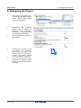
•
In the ‘Project Tree’ pane, rightclick the ‘RX Simulator (Debug
Tool)’. Select ‘Using Debug
Tool -> RX E1(Serial)’.
•
Double-click ‘RX E1(Serial)
(Debug Tool)’ to display the
debugger
tool
properties.
Under ‘Clock’, change the main
clock frequency to 24 MHz.
•
All other settings can remain at
their defaults.
•
Connect the E1 to the PC and
the RSK+ E1 connector.
Connect the +5V PSU to the
PWR connector on the RSK+.
Connect the Okaya PMOD
LCD to the PMOD1 connector.
•
From the ‘Debug’ menu select
‘Download’ to start the debug
session and download code to
the target.
R20UT2930EG0100 Rev. 1.00
Jul 21, 2014
Page 44 of 50
RSK+RX64M
7. Running the Code Generator Tutorial
7.Running the Code Generator Tutorial
7.1
Running the Tutorial
Once the program has been downloaded onto the RSK+ device, the program can be executed.
Click the ‘Go’ button or press F5 to begin the program from the current program counter
position. It is recommended that you run through the program once first, and then continue to
the Tutorial manual to review the code.
R20UT2930EG0100 Rev. 1.00
Jul 21, 2014
Page 45 of 50
RSK+RX64M
8. Additional Information
8.Additional Information
Technical Support
For details on how to use CubeSuite+, refer to the manual available on the DVD or from the web site.
For information about the RX64M group microcontroller refer to the RX64M Group Hardware Manual.
For information about the RX assembly language, refer to the RX Family Software Manual.
Technical Contact Details
Please refer to the contact details listed in section 9 of the “Quick Start Guide”
General information on Renesas microcontrollers can be found on the Renesas website at:
http://www.renesas.com/
Trademarks
All brand or product names used in this manual are trademarks or registered trademarks of their respective
companies or organisations.
Copyright
This document may be, wholly or partially, subject to change without notice. All rights reserved. Duplication of
this document, either in whole or part is prohibited without the written permission of Renesas Electronics
Europe Limited.
© 2014 Renesas Electronics Europe Limited. All rights reserved.
© 2014 Renesas Electronics Corporation. All rights reserved.
© 2014 Renesas Solutions Corp. All rights reserved.
R20UT2930EG0100 Rev. 1.00
Jul 21, 2014
Page 46 of 50
REVISION HISTORY
Rev.
RSK+RX64M Code Generator Tutorial Manual
Date
Description
Page
1.00
Jul 21, 2014
Summary
First Edition issued
Renesas Starter Kit Manual: Code Generator Tutorial Manual
Publication Date:
Rev. 1.00
Jul 21, 2014
Published by:
Renesas Electronics Corporation
http://www.renesas.com
SALES OFFICES
Refer to "http://www.renesas.com/" for the latest and detailed information.
Renesas Electronics America Inc.
2880 Scott Boulevard Santa Clara, CA 95050-2554, U.S.A.
Tel: +1-408-588-6000, Fax: +1-408-588-6130
Renesas Electronics Canada Limited
1101 Nicholson Road, Newmarket, Ontario L3Y 9C3, Canada
Tel: +1-905-898-5441, Fax: +1-905-898-3220
Renesas Electronics Europe Limited
Dukes Meadow, Millboard Road, Bourne End, Buckinghamshire, SL8 5FH, U.K
Tel: +44-1628-651-700, Fax: +44-1628-651-804
Renesas Electronics Europe GmbH
Arcadiastrasse 10, 40472 Düsseldorf, Germany
Tel: +49-211-65030, Fax: +49-211-6503-1327
Renesas Electronics (China) Co., Ltd.
7th Floor, Quantum Plaza, No.27 ZhiChunLu Haidian District, Beijing 100083, P.R.China
Tel: +86-10-8235-1155, Fax: +86-10-8235-7679
Renesas Electronics (Shanghai) Co., Ltd.
Unit 301, Tower A, Central Towers, 555 LanGao Rd., Putuo District, Shanghai, China
Tel: +86-21-2226-0888, Fax: +86-21-2226-0999
Renesas Electronics Hong Kong Limited
Unit 1601-1613, 16/F., Tower 2, Grand Century Place, 193 Prince Edward Road West, Mongkok, Kowloon, Hong Kong
Tel: +852-2886-9318, Fax: +852 2886-9022/9044
Renesas Electronics Taiwan Co., Ltd.
13F, No. 363, Fu Shing North Road, Taipei, Taiwan
Tel: +886-2-8175-9600, Fax: +886 2-8175-9670
Renesas Electronics Singapore Pte. Ltd.
80 Bendemeer Road, Unit #06-02 Hyflux Innovation Centre Singapore 339949
Tel: +65-6213-0200, Fax: +65-6213-0300
Renesas Electronics Malaysia Sdn.Bhd.
Unit 906, Block B, Menara Amcorp, Amcorp Trade Centre, No. 18, Jln Persiaran Barat, 46050 Petaling Jaya, Selangor Darul Ehsan, Malaysia
Tel: +60-3-7955-9390, Fax: +60-3-7955-9510
Renesas Electronics Korea Co., Ltd.
12F., 234 Teheran-ro, Gangnam-Gu, Seoul, 135-080, Korea
Tel: +82-2-558-3737, Fax: +82-2-558-5141
© 2014 Renesas Electronics Corporation. All rights reserved.
Colophon 2.0
RX64M Group
R20UT2930EG0100