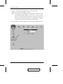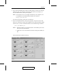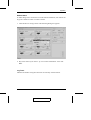
1
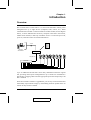
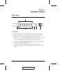
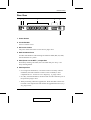
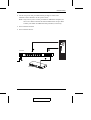
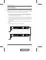
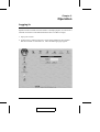
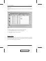
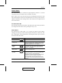
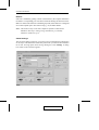
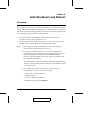
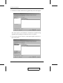
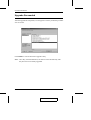
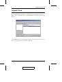
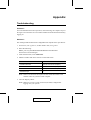
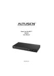
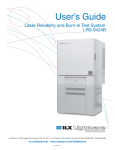
User Manual CP-0108 2004-06-14 Warning! This is a class A product. In a domestic environment this product may cause radio interference in which case the user may be required to take adequate measures. This equipment has been tested and found to comply with the limits for a Class A digital device, pursuant to Part 15 of the FCC Rules. These limits are designed to provide reasonable protection against harmful interference when the equipment is operated in a commercial environment. This equipment generates, uses and can radiate radio frequency energy and, if not installed and used in accordance with the instruction manual, may cause harmful interference to radio communications. Operation of this equipment in a residential area is likely to cause harmful interference in which case the user will be required to correct the interference at his own expense. 2004-06-14 CP-0108 User Manual Packing List The complete CP-0108 package consists of: M 1 CP-0108 Power on the NET Station M 1 CP-0108 to AC Source Power Cable M 1 CP-0108 to Computer Power Cable M 8 Safe Shutdown Cables M 1 PON Cable (DB9 F to DB9 M) M 1 User Manual* M 1 Quick Start Guide M 1 Mounting Kit Check to make sure that all the components are present and that nothing was damaged in shipping. If you encounter a problem, contact your dealer. Read this manual thoroughly and follow the installation and operation procedures carefully to prevent any damage to the unit, and/or any of the devices that connect to it. Note: Features may have been added to the CP-0108 since this manual was written. Please visit our website to download the latest version of this manual. ® © Copyright 2004 ATEN International Co., Ltd. Manual Part No. PAPE-0233-100 Printed in Taiwan 06/2004 All brand names and trademarks are the registered property of their respective owners. iii. 2004-06-14 CP-0108 User Manual Contents 1. Introduction Overview . . . . . . . . . . . . . . . . . . . . . . . . . . . . . . . . . 1 Features . . . . . . . . . . . . . . . . . . . . . . . . . . . . . . . . . . 2 2. Hardware Setup Front View . . . . . . . . . Rear View . . . . . . . . . Installation . . . . . . . . . Before you Begin . . . . Single Stage Installation . Daisy Chaining . . . . . . . . . . . . . . . . . . . . . . . . . . . . . . . . . . . . . . . . . . . . . . . . . . . . . . . . . . . . . . . . . . . . . . . . . . . . . . . . . . . . . . . . . . . . . . . . . . . . . . . . . . . . . . . . . . . . . . . . . . . . . . . . . . . . . . . . . . . . . . . . . 3. Operation Logging In . . . . . . . . . The CP-0108 Main Window Device . . . . . . . . . . System Time: . . . . . . Outlet Status: . . . . . . . . . . . . . . . . . . . . . . . . . . . . . . . . . . . . . . . . . . . . . . . . . . . . . . . . . . . . . . . . . . . . . . . . . . . . . . . . . . . . . . . . . . . . . . . . . . . . . . . . . . . . . . . . . . . . .9 12 12 14 15 4. Safe Shutdown and Reboot Overview . . . . . . . . . . . . . . . Automated Setup . . . . . . . . . . . Installation . . . . . . . . . . . . . Uninstalling . . . . . . . . . . . . Manual Setup . . . . . . . . . . . . . Windows 2000 / XP / Server 2003: NT: . . . . . . . . . . . . . . . . . . . . . . . . . . . . . . . . . . . . . . . . . . . . . . . . . . . . . . . . . . . . . . . . . . . . . . . . . . . . . . . . . . . . . . . . . . . . . . . . . . . . . . . . . . . . . . . . . . . . . . . . . . . . . . . . . . . . . . . . 19 20 20 21 22 22 24 iv. 3 5 6 6 6 8 CP-0108 User Manual 2004-06-14 CP-0108 User Manual 5. Upgrading The Firmware Preparation . . . . . . . . . . . . . Starting the Upgrade . . . . . . . . Upgrade Succeeded . . . . . . . . . Upgrade Failed . . . . . . . . . . . Firmware Upgrade Recovery . . . . Single Station Recovery . . . . . Daisy Chained Station Recovery . . . . . . . . . . . . . . . . . . . . . . . . . . . . . . . . . . . . . . . . . . . . . . . . . . . . . . . . . . . . . . . . . . . . . . . . . . . . . . . . . . . . . . . . . . . . . . . . . . . . . . . . . . . . . . . . . . . . . . . . . . . . . . 25 27 30 31 32 32 32 Appendix Troubleshooting . . . . . . . . . . . . . . . . . . . . . . . . . . . . 33 Specifications . . . . . . . . . . . . . . . . . . . . . . . . . . . . . . 35 Limited Warranty . . . . . . . . . . . . . . . . . . . . . . . . . . . . 36 v. 2004-06-14 CP-0108 User Manual Notes: vi. CP-0108 User Manual 2004-06-14 Chapter 1. Introduction Overview The CP-0108 Power on the NET is a control unit that offers remote power management for up to eight devices (computers, hubs, routers, etc.). When combined with an ATEN or Altusen TCP/IP accessible module (see the diagram below), it allows administrators from any computer connected to the internet, whether down the hall, or half way around the world - to control the power off, power on, and reboot status for each attached device. CN-6000 KN9116 PN9108 SN0108 SN0116 TCP/IP Remote Adminstrator PON (RS-232) CP-0108 Up to 15 additional CP-0108 units can be daisy chained down from the original unit, providing remote power management for up to 128 devices. Installation is fast and easy: plugging cables into their appropriate ports and a simple setup is all that is entailed. Since the CP-0108’s firmware is upgradeable, you can stay current with the latest functionality improvements simply by downloading firmware updates from our website as they become available. CP-0108 User Manual 1 2004-06-14 CP-0108 User Manual With its advanced features and ease of operation, the CP-0108 is the most convenient, most reliable, and most cost effective way to remotely manage power access for multiple computer installations. Features M Remote on/off/reboot control of unattended equipment M Individual control of each port M Manual switching between local and remote access for each port via front panel push button switches M Power on sequence function - power on/off using different periods of delay M Easy setup M Supports safe shutdown and rebooting M User friendly browser-based Java GUI operation M Overcurrent protection and recovery for each AC port - remote users can monitor the current status via the GUI M LEDs for easy status monitoring M Daisy chain up to 15 additional units to manage up to 128 devices M Username and password login security M Configuration can be reset M Upgradeable firmware 2 CP-0108 User Manual 2004-06-14 Chapter 2. Hardware Setup Front View 1 2 3 4 5 6 1. Port LEDs The Port LEDs provide status information about their corresponding AC outlet ports. There is one pair of LEDs for each port. The one on the left is the Remote Access LED; the one on the right is the Power LED: M A Remote Access LED lights GREEN to indicate that the device attached to its corresponding port is capable of being controlled remotely. M An On Line LED lights ORANGE to indicate that the device attached to its corresponding port is up and running. M If both LEDs flash it indicates that there is either an overcurrent situation, or the relay has failed. See Flashing Lightbulb, p. 15, for more details. CP-0108 User Manual 3 2004-06-14 CP-0108 User Manual 2. Firmware Upgrade Switch During normal operation this switch is in the NORMAL position. When performing a firmware upgrade operation it is in the RECOVER position. See Upgrading the Firmware, p. 25, for further details. 3. Power Control Buttons The buttons are identified with a letter (from A to H). Each button controls the power status of its corresponding AC output port (on the unit’s rear panel), as follows: M Pressing and releasing the button toggles the port between Remote Access enabled and Remote Access disabled (Local Mode). If Remote Access is disabled, the switch does not allow the port to be managed from a remote connection. M Under Local Mode, pressing and holding the button in for more than 3 seconds switches the power to its corresponding port On (if it is Off) or Off (if it is On). 4. Reset Switch Pressing and holding this switch in for more that three seconds performs a system reset. Note: This switch is recessed and must be pushed with a thin object - such as the end of a paper clip, or a ballpoint pen. 5. Station ID LED The CP-0108’s Station ID is displayed here. If this is a Single Station installation (see p. 6), or the First Station on a Daisy Chained installation (see p. 8), the CP-0108 has a Station ID of 01. 6. Power Switch This standard rocker switch powers the CP-0108 on and off. 4 CP-0108 User Manual 2004-06-14 Hardware Setup Rear View 1 2 3 4 5 6 1. Power Socket 2. Circuit Breaker Press to reset the circuit. 3. AC Power Outlets The power cables that connect to the devices plug in here. 4. Safe Shutdown Ports Provides safe shutdown and rebooting for Windows 98SE, ME, NT, 2000, XP and 2003 Server systems. 5. PON (Power on the NET ) Output Port When daisy chaining CP-0108s, this is the Chain Out port. See p. 8 for daisy chaining details. 6. PON Input Port M For a single unit installation, or for the first station of a daisy chained installation, the PON cable that connects to the CN-6000 (or other compatible device - see the Overview diagram, p. 1), plugs in here. M In a daisy chained installation, the PON cable from the Chain Out port of the parent unit plugs in here. M When performing a firmware upgrade, the PON cable that connects the CP-0108 to the computer that will transfer the upgraded firmware (see p. 25), plugs in here. CP-0108 User Manual 5 2004-06-14 CP-0108 User Manual Installation Before you Begin 1. Make sure that power to all the devices you will be connecting up have been turned off. You must unplug the power cords of any computers that have the Keyboard Power On function. 2. Make sure that the power supply voltage settings of all the devices you will be connecting up match the voltage of the AC source that the CP-0108 is plugged into. 3. To prevent damage to your installation, make sure that all devices on the installation are properly grounded. Single Stage Installation In a Single Stage installation, there are no additional CP-0108s daisy chained down from the first unit. To set up a single stage installation, refer to the installation diagram below (the numbers in the diagram correspond to the numbered steps), and do the following: 1. Use the PON cable that was provided with this package to connect the CP-0108’s PON IN port to the CN-6000’s (or other compatible device - see the Overview diagram, p. 1) PON port. 2. For each device, use an AC Output cable to connect from any available CP-0108 output port to the device’s AC socket. Note: Only one AC Output cable is provided with this package. For additional cables, contact your dealer. 3. For Windows 98SE, ME, NT, 2000, XP, and Windows Server 2003 systems, for each computer use a Safe Shutdown cable to connect from the CP-0108’s Safe Shutdown port to the computer’s Serial port. Note: 1. This step is optional. 2. You must connect the computer to the same letter designation for both the AC Outlet and Safe Shutdown ports. 6 CP-0108 User Manual 2004-06-14 Hardware Setup 4. Use the AC power cord provided with this package to connect the CP-0108’s Power Socket to an AC power source. Note: Only one AC power cord is provided. For additional computers, be sure to use cables of at least the same standard as the one provided. Contact your dealer for additional cable purchases, if necessary. 5. Turn on the the CP-0108. 6. Turn on the the devices. 2 3 CP-0108 1 4 CN-6000 CP-0108 User Manual 7 2004-06-14 CP-0108 User Manual Daisy Chaining To manage even more devices, up to 15 additional CP-0108s can be daisy chained down from the top level unit. Up to 128 devices can be managed on a complete installation. To set up a daisy chained installation do the following: 1. For each CP-0108 that you add to the chain, use the DB-9 to DB-9 PON cable that was provided with it to connect the parent CP-0108’s PON OUT port to the child CP-0108’s PON IN port. 2. Power up the daisy chained CP-0108s in sequence starting with the highest level parent and working down. In each case, wait for the CP-0108’s Station ID to be ascertained and displayed on the Station ID LED before powering on the next unit. The Station ID for First Stage unit is 01; the ID for the Second Stage unit is 02, etc. 3. After all the CP-0108s are up, power on the devices. 8 CP-0108 User Manual 2004-06-14 Chapter 3. Operation Logging In Operation of the CP-0108 is browser based. For example purposes, we will access a CP-0108 connected to a CN-6000 KVM on the NET module. To begin: 1. Open your browser. 2. In the browser’s URL location bar, specify the IP address of the CN-6000 that the CP-0108 is connected to in . The CN-6000 login page appears: CP-0108 User Manual 9 2004-06-14 CP-0108 User Manual 3. Provide a valid Username and Password (set by the CN-6000 administrator), then Click Login to continue. Note: If you supply an invalid login, the authentication routine will return a message informing you that the “server is busy.” This is a security measure to confuse and discourage hackers from trying to discover a valid Username and Password. If you see this message, try logging in again being careful with the Username and Password. 4. After you have successfully logged in, Click the Power Management icon. 10 CP-0108 User Manual 2004-06-14 Operation 5. A File Download dialog box comes up asking what you want to do with the JCMain.jar file. You can either run it from your browser (click Open), or save it to disk and run it from your computer. Note: You must have Java 1.4 or higher installed on your computer. Java is available for free download from the Sun Java website: http://java.sun.com If your browser permits, run it from your browser. 6. If you save the file and run it from your computer, with your browser still open, go to the directory where the JCMain.jar file resides and either double click its icon, or, from a command window, enter the following command: java -jar JCMain.jar Note: 1. With this method, you must download a new JCMain.jar file each time you access the CP-0108. 2. Make sure not to close the browser before running the JCMain.jar file. The CP-0108 main window comes up: CP-0108 User Manual 11 2004-06-14 CP-0108 User Manual The CP-0108 Main Window The Main Window is divided into three main function panels: Device; System Time; and Outlet Status. The functions provided by each of the panels are described in the sections that follow. Device Since up to 16 CP-0108’s can be daisy chained, this panel specifies which of the CP-0108’s the Main Window Outlet Status panel applies to. The entries found in the Device panel are described below: Station: Station 1 is the ID for the CP-0108 in a standalone installation, or if it is the first station in a daisy chained installation. Station 2 is the next CP-0108 daisy chained down from Station 1. Station 3 is the CP-0108 daisy chained down from Station 2, and so on to Station 16. To set up the Outlets for a daisy chained station click on the arrow to drop the list down; then click to select the station you want to work with. Note: 1. If there is no user input for three minutes, the system times out and another login is required. 2. Each CP-0108’s Station ID is displayed in the Station ID LED on its front panel (see p. 4). 12 CP-0108 User Manual 2004-06-14 Operation Station Name: To make things more convenient on a multi-station installation, each station can be given a distinctive name. To name a station: 1. Click the Device Settings button. The following dialog box appears: 2. Key in the name of your choice - up to 15 letters and numbers - then click Save. Log Total: Indicates the number of log file entries for the currently selected station. CP-0108 User Manual 13 2004-06-14 CP-0108 User Manual View Log: Clicking the View Log button brings up the log file for the currently selected station: M Click Save All to save the contents of the log file to disk. M Click Clear All to empty the contents of the log file M Click Close to exit the View Log utility. System Time: The CP-0108 does not have a system clock. In order for the log file to accurately specify the time of the events it records, you should click on the Sync with PC Set button to sync its time with your computer. 14 CP-0108 User Manual 2004-06-14 Operation Outlet Status: The Outlet Status panel is divided into eight subpanels, labeled A - H, which correspond to the A- H outlets on the CP-0108’s rear panel. Here is where you set up and control the power management functions for each outlet. Each subpanel consists of an information bar across the top; a Power button; a Reboot checkbox; and a Settings button. Their functions are explained in the sections that follow. The Information Bar: The information bar shows the Outlet’s name and power option. These parameters are configured in the Outlet’s Settings dialog box (see p. 16). Power Button: The field with the “traffic light” in it is actually the Outlet’s Power Button. Clicking it turns the power status of the computer attached to its Outlet On or Off. The “traffic lights” provide information concerning the Outlet’s power status as described in the table, below: Indication Status Steady Red Power to the outlet is OFF. Flashing Red Power to the outlet is OFF but Modem Ring Resume has been specified as the remote power option (see Modem Ring Resume, p. 17, for details). Flashing Amber A change in the outlet’s power status is pending. See Modem Ring Resume and System After AC Back, p. 17, for details. Steady Green Power to the outlet is ON. Flashing Lightbulb Indicates that the outlet is either experiencing an overcurrent situtation, or the relay has failed. Click the icon to recover. If the port recovers successfully, it returns to the status it was at before it failed, and the icon changes to reflect the recovered status. If the port cannot recover, you must power off the device attached to the port and restart it. CP-0108 User Manual 15 2004-06-14 CP-0108 User Manual Reboot: If Reboot is enabled (by putting a check in the checkbox), the computer attached to the Outlet’s corresponding port will reboot instead of shutting off when the Power Button is clicked. This selection is disabled (grayed out) if the Outlet isn’t configured for a reboot capable option. See Outlet Settings, p.16, for further details. Note: This function only works with computers capable of a Safe Power Shutdown. See step 3 of Single Stage Installation, p 6, and Safe Shutdown and Reboot, p. 19. Outlet Settings: The Set Outlet dialog box allows you to set up a power management configuration for each port. This determines what takes place when you click the Power Button On or Off. To bring up the Outlet Settings dialog box, Click Settings. A dialog box similar to the one below appears: 16 CP-0108 User Manual 2004-06-14 Operation The settings in the Options panel govern the remote power management features of the CP-0108. The meanings of the field headings are given in the following table: Heading Meaning Outlet Name Each outlet can be given a distinctive name. The maximum number of characters is 15. Modem Ring Resume This is a Safe Shutdown and Reboot option (see p. 19). If this option is selected, when the Outlet’s Power Button is clicked OFF, the CP-0108 waits 90 seconds, and then performs a Safe Shutdown on the computer attached to its Outlet. When the Power Button is clicked ON, the CP-0108 restarts the computer. Note: With this option, although the computer has been turned off, it is still receiving power through the outlet. Therefore, the computer can be locally (physically) turned on or off - in which case the computer’s status may not correspond with the Outlet Status display. The red “traffic light” icon flashes (instead of remains steady) to remind you of this. To make sure that the computer is in sync with the display, click the power On/Off/On (or Off/On/Off) when making a power status change. System after AC back This is a Safe Shutdown option (see p. 19). If this option is selected, when the Outlet’s Power Button is clicked OFF, the CP-0108 waits 105 seconds, and then performs a Safe Shutdown on the computer attached to its Outlet. When the Power Button is clicked ON the CP-0108 restarts the computer. Note: With this option power through the Outlet is cut off. Although it was safely shutdown, the computer does not receive any power through the outlet. Kill the Power If this option is selected, the CP-0108 immediately turns the Outlet’s power ON or OFF when its Power Button is clicked. Turning the power off performs a cold (non-safe) shutdown. Selecting this function disables the Reboot checkbox on the main screen. Confirmation Required If this option is enabled (there is a check in the checkbox), a dialog box comes up asking you to confirm the pending operation before the operation is performed. If it is disabled (there is no check in the checkbox), the operation is performed without confirmation. To save your settings and exit, Click Save. To exit without saving your changes, Click Exit. CP-0108 User Manual 17 2004-06-14 CP-0108 User Manual Notes: 18 CP-0108 User Manual 2004-06-14 Chapter 4. Safe Shutdown and Reboot Overview The CP-0108’s Safe Shutdown and Reboot functions are available for systems running Windows. Safe shutdown and reboot lets you safely close a system down and reboot it without involving the danger to the file systems that simply killing the power supply does. In order to use this function: M You must connect a Safe Shutdown Cable from the CP-0108 to the computer (see Single Stage Installation, p. 6). M You must enable either Modem Ring Resume or System after AC back (but not both) in the computer BIOS’ Power Management settings. Note: 1. The settings you select in the BIOS must match the settings you made in the Set Outlet dialog box (see p. 16). 2. If you choose Modem Ring Resume: 1) your system BIOS must support this function; and 2) check your computer manual to be sure the system supports the COM port External Modem Wakeup function, since some BIOS versions only support this function with an internal PCI card modem. If your BIOS doesn’t support the COM port External Modem Wakeup function, you may wish to install an internal PCI card modem in order to use this function. 3. The wording for the Modem Ring Resume function may vary somewhat from system to system. For example: M Wake On LAN / Ring Connector M Modem Ring On M Power On By External Modem In the BIOS settings, choose Enabled. CP-0108 User Manual 19 2004-06-14 CP-0108 User Manual 4. The wording for the System after AC back function may vary somewhat from system to system. For example: M AC Loss Auto Restart M Restore on AC Power Loss In the BIOS settings, choose Power On (Full On). 5. NT systems must use the System after AC back function. Automated Setup There are two methods to set up safe shutdown and rebooting: Automated, and Manual. This section discusses an automated setup. Manual setup, is discussed on page 22. Automated setup is made possible with the use of the Power Monitor utility supplied on the software CD that came with this package. Power Monitor watches the computer’s power status via the UPS signal. If the UPS signals a power failure or a low battery condition, a dialog box pops up to inform you that the utility will perform a safe shutdown in a few seconds. Installation To install the Power Monitor, simply execute the self extracting setup program(PMMonitorSetup.exe). A copy of PMMonitor.exe is placed in the Windows Startup folder so that it executes each time the system is booted. When monitoring is in effect, a monitoring icon in the form of lightning bolt ( ) is placed in the Windows taskbar to indicate so. When monitoring is temporarily disabled, a canceled lightning bolt icon ( ) is displayed. M You can switch between enabled and disabled by right clicking the icon and selecting Start Monitor or Stop Monitor from the pop up context menu. M You can exit the program by right clicking on the icon and selecting Exit from the pop up context menu. 20 CP-0108 User Manual 2004-06-14 Safe Shutdown and Reboot By default, PMMonitor monitors the COM1 port. If your safe shutdown cable is connected to a different COM port, the utility displays an error message stating that it is unable to open the COM1 port. In this case, stop the monitor program. Right click on the Monitoring Disabled icon, and select Options from the context menu that appears. A dialog box, similar to the one below appears: Open the list of COM ports, and select the COM port that the safe shutdown cable is connected to. Note: Only changes to the COM port selection can be made in this dialog box. Since the utility only monitors the Positive UPS signals, the other settings are fixed. Uninstalling To unistall the utility: 1. Exit the Power Monitor program. 2. Open the Windows Start menu. 3. Choose Programs → Power Monitor → Uninstall Power Monitor. CP-0108 User Manual 21 2004-06-14 CP-0108 User Manual Manual Setup Windows NT, 2000, XP, and Server 2003 can be manually configured for safe shutdown and rebooting instead of using the Power Monitor utility. The following sections explain the procedures involved. Windows 2000 / XP / Server 2003: To set up Windows 2000, XP, or Server 2003 for safe shutdown and rebooting, do the following: 1. Go to the Control Panel; open Power Options; open the UPS page; in the Details panel, click Select. A dialog box similar to the one below appears: a) For the COM port entry, select the COM port on the computer that the Safe Shutdown Cable is plugged into. b) Match the other options to the values shown in the figure above. 22 CP-0108 User Manual 2004-06-14 Safe Shutdown and Reboot 2. Click Next. A dialog box similar to the one below appears: Select the options in the dialog box so that they match the settings shown in the figure above. 3. Click Finish; click OK. To check that the setup is working: 1. Navigate through the following folders: Control Panel → Administrative Tools → Services. 2. In Services, scroll down until you see the Uninterruptible Power Supply entry with Started for its status, as shown in the figure below: CP-0108 User Manual 23 2004-06-14 CP-0108 User Manual NT: 1. Go to the Control Panel; open the UPS entry. A dialog box similar to the one below appears: a) For the COM port entry, select the COM port on the computer that the Safe Shutdown Cable is plugged into. b) Match the other options to the values shown in the figure above. 2. Click OK to finish To check that the setup is working: 1. Navigate through the following folders: Control Panel → Administrative Tools → Services. 2. In Services, scroll down until you see the Uninterruptible Power Supply entry with Started for its status, as shown in the figure below: 24 CP-0108 User Manual 2004-06-14 Chapter 5. Upgrading The Firmware The Windows-based Firmware Upgrade Utility (FWUpgrade.exe) provides a smooth, automated process for upgrading the CP-0108’s firmware. The Utility comes as part of a Firmware Upgrade Package that is specific for each device. New firmware upgrade packages are posted on our web site as they become available. Check the web site regularly to find the latest packages: http://www.aten.com.tw Preparation 1. From a computer that is not part of your KVM installation go to our Internet support site and choose the model name that relates to your device (CP-0108) to get a list of available Firmware Upgrade Packages. 2. Choose the Firmware Upgrade Package you want to install (usually the most recent), and download it to your computer. 3. Use the PON Cable provided with this unit, to connect a COM port on your computer to the CP-0108’s PON In port. CP-0108 User Manual 25 2004-06-14 CP-0108 User Manual 4. Slide the First Station’s Firmware Upgrade switch to the RECOVER position. a) Its Port LEDs blink at half second intervals. b) The STATION ID LEDs display the word, UP, and blink at .5 second intervals. 5. Slide the First Station’s Firmware Upgrade switch back to the NORMAL position. a) The First Station’s STATION ID LEDs display the Station ID’s of all the daisy chained stations in sequence (01’, 02, 03...) b) After the First Station has run through the sequence, its STATION ID LEDs display the word, UP, and blink at 1 second intervals. Its Port LEDs also blink at 1 second intervals. c) Next, all the Port LEDs on the daisy chained stations blink at 1 second intervals, and their STATION ID LEDs display the word, UP, which also blinks at 1 second intervals. d) Finally, all STATION ID LEDs return to displaying their Station ID numbers, indicating that they are ready for the firmware upgrade procedure, and you may start the upgrade. Note: 1. Each station is upgraded in turn. The STATION ID LEDs of the station currently receiving the upgrade display the word, UP, and blink at 1 second intervals. All other STATION ID LEDs display their station numbers, and also blink at 1 second intervals. 2. All stations restart automatically after they have been successfully upgraded. 26 CP-0108 User Manual 2004-06-14 Starting the Upgrade To upgrade your firmware: 1. Run the downloaded Firmware Upgrade Package file - either by double clicking the file icon, or by opening a command line and entering the full path to it. The Firmware Upgrade Utility Welcome screen appears: 2. Read and Agree to the License Agreement (enable the I Agree radio button). CP-0108 User Manual 27 2004-06-14 CP-0108 User Manual 3. Click Next to continue. The Firmware Upgrade Utility main screen appears: The Utility inspects your installation. All the devices capable of being upgraded by the package are listed in the Device List panel. 4. As you select a device in the list, its description appears in the Device Description panel. 28 CP-0108 User Manual 2004-06-14 Upgrading The Firmware 5. After you have made your device selection(s), Click Next to perform the upgrade. If you enabled Check Firmware Version, the Utility compares the device’s firmware level with that of the upgrade files. If it finds that the device’s version is higher than the upgrade version, it brings up a dialog box informing you of the situation and gives you the option to Continue or Cancel. If you didn’t enable Check Firmware Version, the Utility installs the upgrade files without checking whether they are a higher level, or not. As the Upgrade proceeds status messages appear in the Status Messages panel, and the progress toward completion is shown on the Progress bar. CP-0108 User Manual 29 2004-06-14 CP-0108 User Manual Upgrade Succeeded After the upgrade has completed, a screen appears to inform you that the procedure was successful: Click Finish to close the Firmware Upgrade Utility. Note: On a daisy chained installation, all stations restart automatically after they have been successfully upgraded. 30 CP-0108 User Manual 2004-06-14 Upgrading The Firmware Upgrade Failed If the upgrade failed to complete successfully a dialog box appears asking if you want to retry. Click Yes to retry. If you Click No, the Upgrade Failed screen appears: Click Cancel to close the Firmware Upgrade Utility. See the next section, Firmware Upgrade Recovery, for how to proceed. CP-0108 User Manual 31 2004-06-14 CP-0108 User Manual Firmware Upgrade Recovery Single Station Recovery To perform a firmware upgrade recovery, do the following: 1. Power the CP-0108 OFF. 2. Slide the Firmware Upgrade switch to the RECOVER position. 3. Power the CP-0108 back ON. 4. Repeat the upgrade procedure from the beginning. 5. After the upgrade, power the CP-0108 OFF. 6. Slide the Firmware Upgrade switch to the NORMAL position. 7. Power the CP-0108 back ON. Daisy Chained Station Recovery If any of the Stations on a daisy chained installation fails to complete the upgrade procedure successfully: 1. Disconnect it from the chain. 2. Connect your computer to its PON In port (with the PON Cable). 3. Perform the upgrade recovery procedure on it as for a single station recovery. After the upgrade completes, connect it back into the chain. 32 CP-0108 User Manual 2004-06-14 Appendix Troubleshooting Problem 1: On a safe shutdown and reboot operation, when rebooting, the computer stops at the logon screen and waits for a Username and Password instead of automatically logging on. Solution 1: The Autologon function hasn’t been configured for the computer. Set it up as follows: 1. For Win NT, run regedit.exe; for Win 2000 or XP, run regedt32 2. Select the following: HKEY_LOCAL_MACHINE\SOFTWARE\Microsoft\Windows NT\Current Version\Winlogon 3. Under the Edit menu, select Add Value. 4. Add the variables and values as shown in the table below: Name Value DefaultDomainName [domain name for this computer] DefaultUserName [user name for this computer] DefaultPassword [user password for this computer] AutoAdminLogon 1 Note: Remove the brackets and replace the text inside the brackets with suitable values for yourself on this computer. 5. Close the Registry Editor. Note: Make sure you have a real password (not blank) configured for logging on to your system. CP-0108 User Manual 33 2004-06-14 CP-0108 User Manual Problem 2: The computer has an older mainboard that doesn’t support APM in the BIOS. What can I do to get Safe Shutdown and Reboot working? Solution 2: If you are running Windows 2000, XP, or Server 2003, you can do the following: 1. Open Control Panel → Power Options. 2. Open Properties → APM. 3. Enable Advanced Power Management support. 34 CP-0108 User Manual 2004-06-14 Upgrading The Firmware Specifications Function Specification Power Inlet 1 x IEC 60320/C14 (M) Power Outlets 8 x IEC 60320/C13 (F) Input Current (Total input) 100 ~ 120V, 50/60Hz, 15A; 220 ~ 240V, 50/60Hz, 10A Output Current1 100 ~ 120V, 50/60Hz, 10A; 220 ~ 240V, 50/60Hz, 10A LEDs Connectors Switches Online 8 (green) Remote Access 8 (orange) Station ID 2 x 7 segment (yellow) 2 Data In 1 x DB-9 (F) Chain Out 1 x DB-9 (M) Safe Shutdown 8 x 6-pin RJ-11 (F) Power 1 x Rocker Outlet On / Off Remote On / Off 8 x Pushbutton FW Upgrade 1 x 2 position slide Reset 1 x Semi hidden Environment Operating Temperature: 0 ~ 50oC Storage Temperature: -20 ~ 60oC Humidity: 0 ~ 80% RH Noncondensing Housing Metal Weight 3.7 kg Dimensions (L x W x H) 43.2 x 21 x 4.5 cm 1. The figures shown are for a per port maximum, but the total output for all 8 ports equals the total input. 2. This is a multifunction port that can be used: to connect a local console; as the Chain In port on a daisy chained installation, and as the Firmware Upgrade port. CP-0108 User Manual 35 2004-06-14 CP-0108 User Manual Limited Warranty IN NO EVENT SHALL THE DIRECT VENDOR’S LIABILITY EXCEED THE PRICE PAID FOR THE PRODUCT FROM THE DIRECT, INDIRECT, SPECIAL, INCIDENTAL OR CONSEQUENTIAL DAMAGES RESULTING FROM THE USE OF THE PRODUCT, DISK OR ITS DOCUMENTATION. The direct vendor makes no warranty or representation, expressed, implied, or statutory with respect to the contents or use of this documentation, and specially disclaims its quality, performance, merchantability, or fitness for any particular purpose. The direct vendor also reserves the right to revise or update the device or documentation without obligation to notify any individual or entity of such revisions, or update. For further inquires please contact your direct vendor. 36 CP-0108 User Manual 2004-06-14