1
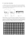
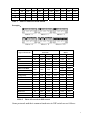
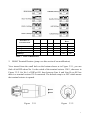
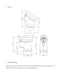
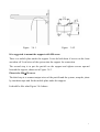
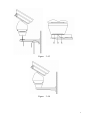
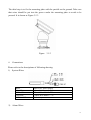
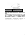
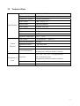
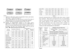
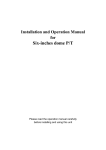
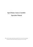
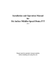
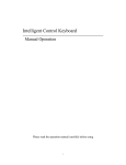
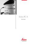
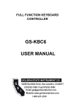
For PELCO-D and PELCO-P protocol, please use CALL + 91 , That will trigger the tracking tour
If you are using B01 protocol,use SHOT + 1 + ENTER for tracking tour
Operation Manual of
Outdoor High-Speed Pan/Tilt
V 1.3
You are pleased to read the manual carefully before using the product.
Sign of Safety
ATTENTION
Please Do Not Open to
Avoid Electrical Shock!
Attention:
Please do not dismount it by yourself to avoid
electrical shock. There is no part inside, which
needs customer to repair it. All repair work
should be carried out by eligible person.
The flashing arrow in the upward triangle
is used to remind customer that there is
larger “non-insulated dangerous voltage”
exists near the product, which can cause
danger upon human body.
The notice mark in the upward triangle is
used to remind customer to refer to
important operation and instructions of
maintenance of the product.
The manufacture no. of the machine is marked on the
bottom or on the side. Please fill out the manufacture no.
on the blank below and keep the operation manual well
for reference if needed.
Model:
_____________________________________
Manufacture No. ______________________________
CONTENTS
I
Points for Attention ………………………………….………….……… 1
II
Introduction of Functions …………………………………….………. 2
III
Quick Guide of Installation ………………………………….……….. 3
1. Modify the Protocol and the Address ……………………………….….. 3
2. RS485 Terminal Resistor ………………………………………………..…. 5
3. Sizes …………………………………………………….…………………… 6
4. Wall Mounting ………………………………………….………………….. 6
5. Base Plate Mounting …………………………………….…………………. 9
6. Connection ………………………………………………………………… 10
IV
Description of Functions of the Menu ……..……………………… 12
1. Basic Operation of the Menu …………………………………………….. 12
2. Setup of the Menu ………………………………………………………… 12
3. Appendix of the Menu ……………………………………………………. 14
V
Special Operation ……………………..………………………………. 16
VI
Technical Data ………………………………………………………….. 17
I
Notes for Attention
1. Read the manual carefully before installing the product.
2. Power Supply: 220V/110V/24V, refer to the sticker on the product.
3. There are sophisticated optical and electronic components inside the product.
Avoid incorrect operation methods such as heavy pressing or strong vibration
during the course of transportation, store and installation otherwise the product
could be damaged.
4. Please do not dismount components inside the product to avoid occurrence of
trouble. There is no part inside the product, which needs repair by customer
himself.
5. Observe all electric safety standard in application and adopt special power supply
attached the product. RS-485 and video signal should keep enough distance with
the high voltage devices and cable during the course of transmission, and take
protection measures such as anti-lightning and surging etc. id necessary.
6. Do not apply the product under the state which exceeds limited temperature,
humidity or specifications of power supply.
7. Do not aim the camera at the sun or very bright object, or to monitor bright and
still object whether the power supply is switched on or off.
8. Do not clean the product with strong or abrasive detergent. Clean out dirt with
dry cloth or mild detergent if dirt is not easily removed.
9. Take care to apply the product to avoid collision or vibration. Improper
application can cause damage.
10. Install the product on the place where it has enough supportability.
11. Wipe dust on the lens with special lens paper.
1
II
Introduction of Functions
1. Unlimited rotation 360° horizontally and from +33° to -80° vertically.
2. The horizontal speed is 0 - 40°/sec while the vertical speed is 0 - 20°/sec (wind
speed less than 50 miles/hour).
3. At the preset position, the horizontal speed is 0 - 100°/sec while the vertical
speed is 0 - 40°/sec (wind speed less than 50 miles/hour).
4. Automatic control of constant temperature, manual rain wiper/defroster control.
5. IP grade IP66.
6. The bearable maximum wind speed is 130 miles/hour.
7. 128 preset positions in memory and 6 groups of programmable patrol loci, as
well as linear scan between two points with adjustable speed and variable
direction,
8. 16 common protocols integrated, four kinds of baud rate 2400/4800/9600/19200
bps available and 1024 addresses are supported (0 - 1023).
2
III Quick Guide of Installation
1.
Modify the Protocol and the Address (jump over this section if no modification)
Take out the small metal cover on the bottom shown as dotted-lined part on Figure
3.1.1 to expose DIP switch of the address and the protocol shown as Figure 3.1.2. The
detailed drawing is shown as in Figure 3.1.1.
Figure 3.1.1
Figure 3.1.2
Figure 3.1.3
Shown as Figure 3.1.3, the 10-bit DIP stands for the addresses which can be from 0 to
1023. The 6-bit DIP stands for the protocols in which bits 1-4 mean the protocol
while bits 5-6 means the baud rate. Push the DIP downward means ON otherwise it
means OFF. For example the address in the figure means 1 while the protocol means
PELCO-D with the baud rate of 2400bps which can be found from the table.
Status of DIP Switch
Address
of PT
DIP-1
DIP-2
DIP-3
DIP-4
DIP-5
DIP-6
DIP-7
DIP-8
DIP-9
DIP-10
1
ON
OFF
OFF
OFF
OFF
OFF
OFF
OFF
OFF
OFF
2
OFF
ON
OFF
OFF
OFF
OFF
OFF
OFF
OFF
OFF
3
ON
ON
OFF
OFF
OFF
OFF
OFF
OFF
OFF
OFF
4
OFF
OFF
ON
OFF
OFF
OFF
OFF
OFF
OFF
OFF
5
ON
OFF
ON
OFF
OFF
OFF
OFF
OFF
OFF
OFF
6
OFF
ON
ON
OFF
OFF
OFF
OFF
OFF
OFF
OFF
7
ON
ON
ON
OFF
OFF
OFF
OFF
OFF
OFF
OFF
8
OFF
OFF
OFF
ON
OFF
OFF
OFF
OFF
OFF
OFF
9
ON
OFF
OFF
ON
OFF
OFF
OFF
OFF
OFF
OFF
10
OFF
ON
OFF
ON
OFF
OFF
OFF
OFF
OFF
OFF
11
ON
ON
OFF
ON
OFF
OFF
OFF
OFF
OFF
OFF
12
OFF
OFF
ON
ON
OFF
OFF
OFF
OFF
OFF
OFF
13
ON
OFF
ON
ON
OFF
OFF
OFF
OFF
OFF
OFF
14
OFF
ON
ON
ON
OFF
OFF
OFF
OFF
OFF
OFF
15
ON
ON
ON
ON
OFF
OFF
OFF
OFF
OFF
OFF
3
16
OFF
OFF
OFF
OFF
ON
OFF
OFF
OFF
OFF
OFF
17
ON
OFF
OFF
OFF
ON
OFF
OFF
OFF
OFF
OFF
18
OFF
ON
OFF
OFF
ON
OFF
OFF
OFF
OFF
OFF
…
…
…
…
…
…
…
…
…
…
…
1023
ON
ON
ON
ON
ON
ON
ON
ON
ON
ON
Table 1
Table of Addresses in DIP Switch
Examples:
Type of Protocols
Selection of Communication
Protocols
DIP-1
DIP-2
DIP-3
DIP-4
Common Baud
Rates
DIP-5
DIP-6
SAMSUNG
ON
OFF
OFF
OFF
OFF
ON
B01
ON
OFF
OFF
OFF
OFF
ON
NEON
ON
OFF
OFF
OFF
OFF
ON
Santachi
OFF
ON
OFF
OFF
OFF
ON
PELCO-D
ON
ON
OFF
OFF
OFF
OFF
OFF
OFF
ON
OFF
ON
OFF
OFF
ON
PANASONIC
ON
OFF
ON
OFF
OFF
ON
Longcomity
OFF
ON
ON
OFF
OFF
ON
HUNDA600
ON
ON
ON
OFF
OFF
ON
LILIN
OFF
OFF
OFF
ON
OFF
ON
VICON
ON
OFF
OFF
ON
ON
OFF
MOLYNX
OFF
ON
OFF
ON
OFF
ON
KALATEL
ON
ON
OFF
ON
ON
OFF
VCL
OFF
OFF
ON
ON
OFF
ON
Reserved
ON
OFF
ON
ON
OFF
ON
ALEC
OFF
ON
ON
ON
OFF
ON
Ultrak
ON
ON
ON
ON
OFF
ON
PELCO-P/4800
PELCO-P/9600
Table 2
Table of Protocols in DIP Switch
Some protocols and their common baud rates in DIP switch are as follows:
4
Baud Rates of
Communication
DIP-1
DIP-2
DIP-3
DIP-4
2400 bps
-
-
-
-
OFF
OFF
4800 bps
-
-
-
-
ON
OFF
9600 bps
-
-
-
-
OFF
ON
19200 bps
-
-
-
-
ON
ON
Table 3
2.
Setup of Baud
Rates
DIP-5
DIP-6
Table of Baud Rates
RS485 Terminal Resistor (jump over this section if no modification)
View inward from the small hole on the bottom shown as in Figure 3.2.1, you can
find a 4-bit DIP whose No.1 is the switch of the terminal resistor 120Ω, shown as in
Figure 3.2.2. Set No.1 of DIP at ON, then between Line A and Line B on 485 bus
there is a terminal resistor 120Ωconnected. The default setup is at OFF which means
the terminal resistor is opened.
Figure 3.2.1
Figure
3.3.2
5
3. Sizes
4.
Wall Mounting
The first step is to mount the bracket on the wall which is shown as in Figure 3.4.1.
Figure 3.4.2 is the drawing of sizes of mounting holes.
6
Figure 3.4.1
Figure 3.4.2
It is suggested to mount the support with M8 screw.
There is a mobile plate under the support. It can be laid down if screws on the front
are taken off. Lead wires of the system into the support for connection.
The second step is to put the pan/tilt on the support and tighten screws upward
beneath the support, shown as in Figure 3.4.3.
Please take M6×20 screw.
The third step is to connect output wires of the pan/tilt and the system, wrap the joints
by insulation tape and fix the mobile plate under the support.
It should be like what Figure 3.4.4 shows.
7
Figure 3.4.3
Figure 3.4.4
8
5.
Base Plate Mounting
The first step is to drill holes on the ground referring to the positions of holes on the
mounting plate. The sizes of holes are shown as in Figure 3.5.1.
Figure 3.5.1
The second step is to fix the mounting plate on the bottom of the pan/tilt by M6×20
screw.
Figure 3.5.2
9
The third step is to fix the mounting plate with the pan/tilt on the ground. Take care
that wires should be put into the groove under the mounting plate to avoid to be
pressed. It is shown as Figure 3.5.3.
Figure 3.5.3
6.
Connections
Please refer to the descriptions of following drawing.
1) System Wires
RED
BLACK
YELLOW
ORANGE
VIDEO OUT
Input of AC Power Supply
Input of AC Power Supply
Control Wire RS485-(B)
Control Wire RS485+(A)
Video Output
2) Alarm Wires
10
Red
Green
White
Blue
Red
Yellow
Green, Blue
Alarm Input 1
Alarm Input 1
Alarm Common Terminal
The alarm input should be switch signal otherwise internal circuit shall be
damaged.
The alarm shall be linked with the presser point, which should be set in the
menu. In case two channels have alarm signals simultaneously, the pan/tilt
shall response upon two channels one by one with the time interval of 2
seconds.
In case the alarm signal is inputted, the PT shall have no response upon
functions such as “AUTO PAN”, “Patrol” and “Pattern” and so on.
11
IV Description of Functions of the Menu
1.
Basic Operations on the Menu
Open the main menu by the control keyboard or the matrix via the instruction of “Call Preset 64”.
In addition the main menu can be also opened by “Call Preset 1” twice within 4 seconds.
When the menu is displayed on the screen, operate “TILT UP”, “TILT DOWN” to move the cursor
to the options to be set up, and operate “PAN LEFT”, “PAN RIGHT” to modify the content or the
instruction to enter into this option.
The operation can be accelerated in case the joystick is pushed towards one direction for more than
1 second.
All setups of the menu shall not be lost even after power failure.
The application under special cases can be seen in the instruction of functions of the menu.
2. Setup of the Menu
2.1 Main Menu
DISPLAY SETUP: Enter into the submenu to setup display on the screen, such as ID DISPLAY,
TITLE DISPLAY and CAMERA DISPLAY.
CAMERA SETUP: Enter into the submenu of normal data of the
camera.
CONTROL SETUP: Enter into the submenu of the control data of the
PT.
PROGRAM: Enter into the submenu to setup enhanced function of the
PT.
CAM DEFAULT SET: Restore camera default settings.
RESET PT: Reset of the PT.
EXIT: Exit the main menu.
2.2 Display Setup
ID DISPLAY: When this option is set at ON, the monitor shall
display the address of the camera such as “CAM 001”.
ID POS: To set up the display location of the address, which can
be displayed at TOP-L (top left), TOP-R (top right), BOTT-R
(bottom right) and BOTT-L (bottom left).
TITLE DIS: when this option is set at ON, the title of the presets
can be displayed on the left of the screen when the preset is called,
such as “NO.001 ABCDEFGH”. If no title is set, then only “NO. 001” is displayed. The
modification of the title of the preset is set on the PROGRAM option.
TITLE POS: to set the display location of the title of the preset, which can be from Line 1 to Line
10. The Line 1 is on the top of the screen.
CAM DISPLAY: when this option is set at ON, the display screen of the camera can be displayed.
RETURN: to exit the main menu.
12
Camera Setup
SLOW SHUTTER: Slow Shutter function with Man/Auto options.
When the option be AUTO, ASS shall be displayed on the monitor.
BACK LIGHT: Backlight Compensation ON/OFF.
ICR SHOT: Low Illumination, ON–open/AUTO–automatic.
IRIS: Automatic Exposure, AUTO–automatic/MANU–manual.
D-ZOOM: Digital Zoom, ON–open/OFF–close.
FOCUS: Automatic focusing, AUTO–automatic/MANU–manual.
WB SET: White Balance, ATW /INDOOR /OUTDOOR /ONEPUSH
/AUTO /MANU
MENU OF CAM: this option is empty.
RETURN: return to the main menu.
Control Setup
WIPER: rain wiper control.
DEFROSTER: defroster control.
RESERVED AUX: auxiliary switch control.
ALARM1: external alarm 1 control.
LINKAGE1: set linkage with external alarm 1.
ALARM2: external alarm 2 control.
LINKAGE2: set linkage with external alarm 2.
HOME OPTION: enter the submenu of automatic home function.
AUTO HOME: when this option is set at ON, home position
function is opened. This means the PT shall return home
position if user has no any action in a period of time. The PT
cannot return home position automatically if it is under the
patrol state. If no home returning is needed under the stop state,
please set this option at OFF.
HOME POS: set home position. HOME POS can be sat from preset 1 to preset 63, or preset 65
to preset 128.
DWELL TIME: set the time for home position, which means the PT shall go to home position
if no any control occurs within the set time from 1 to 99 minutes.
RETURN: return to the menu one level up.
RETURN: return to the main menu.
Program
AUTO PAN START POS: to set the start point of the AutoPan.
After entering, move the PT by the joystick. Push CLOSE button
to save the current position and return.
AUTO PAN END POS: to set the end point of the AutoPan.
After entering, move the PT by the joystick. Push CLOSE button
to store the current position and return.
RUN AUTO PAN: to run the AutoPan. Please set the start point
and the end point first. If the start position and the end position is
the same position, the PT shall make 360°AutoPan. The speed of
the AutoPan is divided into six grades: FAST/NORMAL/SLOW/
13
-FAST/-NORMAL/-SLOW. The first three grades are the AutoPan less than 180° while the latter
three grades are the AutoPan larger than 180°. The speed can be adjusted by PAN LEFT/PAN
RIGHT. Push OPEN button to run and exit the menu. The start point and the end point are set from
options 1 and 2 on this menu.
SET TITLE: to edit the titles of preset. Only first 63 presets may have their titles and the preset
number can be selected by PAN LEFT/PAN RIGHT. Press OPEN button to enter into the edit
state and press CLOSE button to exit the edit state. Operations under the edit state can be seen
thereafter.
SET PATROL: to edit patrol data. Select the number of patrol by PAN LEFT/PAN RIGHT. Press
OPEN button to enter into the edit state and press CLOSE button to exit the edit state. Operations
under the edit state can be seen thereafter.
RUN PATROL: to run patrol function. Select the number of patrol by PAN LEFT/PAN RIGHT.
Press OPEN button to run and exit the menu.
RECORD PATTERN: to recode pattern. It can remember PTZ operation for 40 seconds. Complete
the edit when 40 seconds are up or push CLOSE button.
RUN PATTERN: to playback pattern. You can also control the joystick to stop running.
RETURN: return to the main menu.
3. Appendix of the Manu
Operation of Patrol under the Edit State
After entering into the edit state, the screen shows as follows:
NO – serial number of patrol
POS – number of preset
SP – leaving speed
TM – dwelling time
Enter into edit state, display on screen is as follows:
Edit Area, one line shows data of two point .
SEQ: 01 – it means current set patrol 1
CLOE: EXIT – push CLOSE to exit edit state
The top line and the bottom line display prompt message, and the middle area displays information
of each locus, one line shows data of two points. Move the cursor by PAN LEFT/RIGHT and
modify data by TILT UP/DOWN. Press the button down for 1 second to accelerate. Press CLOSE
button to exit the edit state and store modification. In above figure, the program stores four patrol
points. The settable range of POS is from 1 to 63 or 65 to 128. In case POS is “---“, it means the
skip this point. The settable range of SP is from 0 to 8 (0 and 1 are same at the highest speed while
grade 8 has the lowest speed). The settable rage of TM is from 0 to 99 seconds.
14
Operation of the Title of Preset under Edit State
After entering into the edit state, the screen show as the drawing.
You can find current setup is the preset 1 with the title “NO
TITLE”. Move the cursor by PAN LEFT/RIGHT and modify data
by TILT UP/DOWN. Press the button down for 1 second to
accelerate. Press CLOSE button to exit the edit state and save
modification. The title of preset can contain 8 characters such as
0~9, A~Z, +, - and blank. Note: the first letter should be 0~9 or A~Z otherwise it means to delete
the title of the presets and it shall only show “NO.XXX” without the title when preset points.
15
V Special Operation
The preset 51 to 60 are used for special functions. It has special meanings to set or
call these points. Therefore these points should not be used in functions of automatic
operation of the pan/tilt such as multiple points patrol, external alarm linkage etc. so
as to avoid error actions.
Preset
51
52
53
54
55
56
57
58
59
60
Set Preset
Wiper ON
Defroster ON
Auxiliary Output AC24V ON
Linkage of External Alarm 1 ON
Linkage of External Alarm 2 ON
Reserved
Reserved
Reserved
Reserved
Reserved
Call Preset
Wiper OFF
Defroster OFF
Auxiliary Output AC24V OFF
Linkage of External Alarm 1 OFF
Linkage of External Alarm 2 OFF
Reserved
Reserved
Reserved
Reserved
Reserved
16
VI
Technical Data
Image Inductor
1/4″ Color CCD
Effective Pixels
752H×582V (440000pixels)
Synchronous System
External synchronous
Video Output
VBS 1.0Vp-p/75Ω
White Balance
Automatic/Manual
Power Supply
AC220V/110V/24V
Power Consumption
70W
Weight
13Kg
Relative Humidity
10-75% (in case no condensation)
Operation Temperature
-35°C ~ +55°C
Scan System
15.625KHz (H)
Horizontal Resolution
480 lines
Camera
Signal/Noise Ratio
Larger than 48db
Function
Electronic Shutter
1/3~1/10000 seconds
Specifications
Lowest Illumination
PAL
50Hz (V)
0.01~1Lux (F1.6)
(determined by different model of camera)
x16、x18、x22、x23、x25 optical zoom
Parameters of
Lens
Zoom rate
and x4 electronic zoom
(determined by different model of camera)
Iris
Automatic/Manual
Focus
Automatic/Manual
17