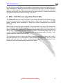
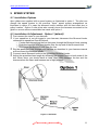
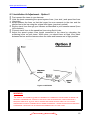
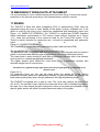
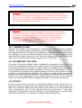
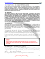
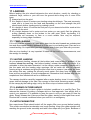
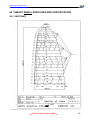
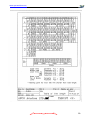
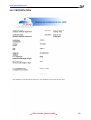
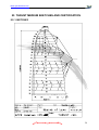
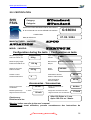
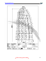
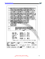
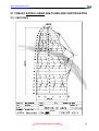
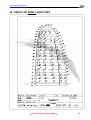
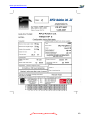
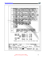
1
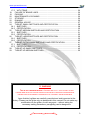
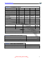
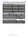
Revision 4, 13.02.2007 APCO Aviation Setting Future Standards Factory: 7, Chalamish Street - Industrial Park - Caesarea 38900 ISRAEL www.apcoaviation.com Tel: +972 4 6273727 Fax +972 4 6273728 www.apcoaviation.com CONTENTS: 1 DISCLAIMER OF LIABILITY.................................................................................... 6 2 CONSTRUCTION.................................................................................................... 6 3 MATERIALS ............................................................................................................ 6 4 BUTT HOLES (Velcro closures on wing tips)........................................................... 7 5 HIT VALVES (High speed In-Take) ......................................................................... 7 6 SRS – Stall Recovery System [Thrust HP] .............................................................. 8 7 TRIMMING............................................................................................................. 10 8 HARNESS ............................................................................................................. 10 9 SPEED SYSTEM................................................................................................... 11 9.1 Installation Options ......................................................................................... 11 9.2 Installation & Adjustment - Option 1 (default) ................................................. 11 9.3 Installation & Adjustment - Option 2 ............................................................... 12 10 EMERGENCY PARACHUTE ATTACHMENT.................................................... 13 11 RISERS.............................................................................................................. 13 12 RISERS (THRUST HP) ...................................................................................... 16 13 TRIMMERS ........................................................................................................ 17 14 INSPECTION ..................................................................................................... 17 14.1 GENERAL ...................................................................................................... 17 14.2 BRAKE SETTING ........................................................................................... 17 14.3 FIRST CHECK AND PREFLIGHT INSPECTION ........................................... 18 14.4 REGULAR INSPECTION CHECKS................................................................ 18 14.5 LINE MAINTENANCE..................................................................................... 18 15 LAUNCHING ...................................................................................................... 19 15.1 LAYOUT ......................................................................................................... 19 15.2 ALPINE LAUNCH OR FORWARD LAUNCH.................................................. 19 15.3 STRONG WIND AND REVERSE LAUNCH ................................................... 20 15.4 WITH PARAMOTOR ...................................................................................... 20 15.5 WITH TRIKE................................................................................................... 20 16 FLIGHT TECHNIQUES ...................................................................................... 20 16.1 STRAIGHT FLIGHT WITH ENGINE ............................................................... 20 16.2 FLYING SPEED ............................................................................................. 20 16.3 THERMAL FLYING......................................................................................... 21 16.4 ASYMMETRIC COLLAPSE............................................................................ 21 16.5 CRAVAT ......................................................................................................... 21 16.6 FRONT STALL OR SYMMETRIC COLLAPSE............................................... 22 16.7 B-STALL ......................................................................................................... 22 16.8 BIG EARS....................................................................................................... 22 16.9 DEEP STALL OR PARACHUTAL STALL....................................................... 22 16.9.1 Signs of parachutal stall .......................................................................... 22 16.9.2 Exit from parachutal stall ......................................................................... 23 16.10 FULL STALL ............................................................................................... 23 16.11 NEGATIVE TURN (Stall on one side) ......................................................... 23 16.12 SPIRAL DIVES ........................................................................................... 24 16.13 STRONG TURBULENCE ........................................................................... 24 16.14 STEERING NOT FUNCTIONING ............................................................... 24 17 LANDING ........................................................................................................... 25 17.1 TREE LANDING ............................................................................................. 25 17.2 WATER LANDING.......................................................................................... 25 17.3 LANDING IN TURBULENCE.......................................................................... 25 17.4 WITH PARAMOTOR ...................................................................................... 25 2 www.apcoaviation.com 17.5 WITH TRIKE................................................................................................... 26 18 FAILURE OF BRAKE LINES.............................................................................. 26 19 PACKING ........................................................................................................... 26 20 MAINTENANCE & CLEANING .......................................................................... 26 21 STORAGE.......................................................................................................... 26 22 DAMAGE............................................................................................................ 26 23 GENERAL ADVICE............................................................................................ 27 24 THRUST SMALL SKETCHES AND CERTIFICATION....................................... 28 24.1 SKETCHES .................................................................................................... 28 24.2 CERTIFICATION ............................................................................................ 30 25 THRUST MEDIUM SKETCHES AND CERTIFICATION .................................... 31 25.1 SKETCHES .................................................................................................... 31 25.2 CERTIFICATION ............................................................................................ 35 26 THRUST LARGE SKETCHES AND CERTIFICATION ...................................... 36 26.1 SKETCHES .................................................................................................... 36 26.2 CERTIFICATION ............................................................................................ 40 27 THRUST EXTRA LARGE SKETCHES AND CERTIFICATION ......................... 41 27.1 SKETCHES .................................................................................................... 41 27.2 CERTIFICATION ............................................................................................ 45 28 THRUST HP SMALL SKETCHES...................................................................... 46 29 THRUST HP MEDIUM SKETCHES................................................................... 50 !!! WARNING THIS IS NOT TRAINING MANUAL. ATTEMPTING TO FLY THIS OR ANY OTHER PARAGLIDER WITHOUT PROPER INSTRUCTION FROM A CERTIFIED PROFESSIONAL INSTRUCTOR IS EXTREMELY DANGEROUS TO YOURSELF AND BYSTANDERS. Apco Aviation's gliders are carefully manufactured and inspected at the factory. Please use the glider only as described in this manual. Do not make any modifications to the glider. As with any sport – without taking the necessary safety precautions, paragliding can be dangerous. 3 www.apcoaviation.com THRUST TECHNICAL DATA [m2] [m2] [m] [m] Small 42 27.3 23.4 11.58 9.32 4.91 3.71 Medium 44 29.3 25.2 12.2 9.85 5.08 3.85 Large 46 31.3 26.9 12.9 10.4 5.31 4.02 X-Large 48 33.3 28.6 13.5 10.9 5.47 4.15 [kg] 70-115 85-135 100-155 110-180 [kg] 65-85 0-100 95-120 110-140 [kg] [m] [m] [m] [m] 6.5 3.03 0.58 6.6 407 6.9 3.05 0.58 7.0 421 7.3 3.05 0.58 7.4 441 7.6 3.05 0.58 7.7 481 Size Cells Area Area (projected) Span (incl. Stabilizer) Span (projected) Aspect Ratio Aspect Ratio (projected) Pilot Weight (All up + paramotor) Pilot Weight (All up for free flight) Weight of Canopy Root Cord m Tip Cord m Length of Lines on B Total length of line used LINES Top Middle Bottom Material Diameter (∅mm) Dyneema Superaramidee Superaramidee 1.1 1.2 / 1.8 1.8 / 1.9 Sail Cloth Rib Reinforcement Warranty FABRIC THRUST PERFORMANCE DATA V-min. V-trim V-max. Paramotor Version (P/M) V-max. Paraglider Version (P/G) Min Sink ( at optimum wing loading) THRUST CERTIFICATION DATA THRUST SMALL THRUST MEDIUM THRUST LARGE THRUST X-LARGE Strength (kg) 95 110 / 220 220 / 320 46gr/m2 "Zero Porosity" Ripstop Nylon 180gr/m2 Mylar (Trilam) 3 Years / 250 hours 21 km/h 37 km/h 50 km/h 45 km/h 1.1 m/s AFNOR AFNOR AFNOR AFNOR Standard Standard Standard Standard 4 www.apcoaviation.com THRUST HP TECHNICAL DATA Size Cells Area m2 Area (projected) m2 Span (incl. Stabilizer) m Span (projected) m Aspect Ratio Aspect Ratio (projected) Pilot Weight, Kg (all up + paramotor) Weight of Canopy Kg Root Cord m Tip Cord m Length of Lines on B m Total length of line used m Small 41 26.2 22.2 11.3 9.05 4.87 3.69 75-140 6.3 3.00 0.58 6.4 399 LINES Top Middle Bottom Medium 42 27.5 23.5 11.6 9.35 4.9 3.72 100-165 6.5 3.00 0.58 6.6 407 Material Diameter (∅mm) Dyneema Superaramidee Superaramidee 1.1 1.2 / 1.8 1.8 / 1.9 Sail Cloth Rib Reinforcement Warranty FABRIC THRUST HP PERFORMANCE DATA V-min. V-trim V-trim off V-max Min Sink ( at optimum wing loading) Strength (kg) 95 110 / 220 220 / 320 "Zero Porosity" Ripstop Nylon 180gr/m2 Mylar (Trilam) 3 Years / 250 hours 22 km/h 38-40 km/h 45-47 km/h 60+ km/h 1.2 m/s 5 www.apcoaviation.com 1 DISCLAIMER OF LIABILITY Taking into consideration the inherent risk in paragliding, it must be expressly understood that the manufacturer and seller do not assume any responsibility for accidents, losses and direct or indirect damage following the use or misuse of this product. APCO Aviation Ltd. is engaged in the manufacture and sale of hang gliding, paragliding, motorized para/hang gliding and emergency parachute equipment. This equipment should be used under proper conditions and after proper instruction from a qualified instructor. APCO Aviation Ltd. has no control over the use of this equipment and a person using this equipment assumes all risks of damage or injury. APCO Aviation Ltd. disclaims any liability or responsibility for injuries or damages resulting from the use of this equipment. The glider is designed to perform in the frame of the required class as certified by AFNOR / CEN. 2 CONSTRUCTION The glider is constructed with a top and bottom surface, connected by ribs. One top and bottom panel, together with the connecting ribs is called a cell. Each cell has an opening on the front lower part. The cells fill with air forcing the panels to take the shape dictated by the airfoil (rib) section. On either side the wing ends in a stabilizer or wing tip, which provides straight-line (Yaw) stability and produces some outward force to keep the span-wise tension. The front part of the ribs is made from Trilam to keep the leading edge shape at high speeds and in turbulent air. It also improves the launch characteristics of the glider. The line hook-up points are made of Dyneema or Nylon tape. 3 MATERIALS The glider is made from tear resistant Ripstop Nylon cloth, which is P.U. coated to zero porosity and then siliconized to give the fabric high resistance to the elements. Different cloth is used for the top, bottom and ribs due to their different functions. The lines are made of Superaramide covered with a polyester sheath for protection against UV, wear and abrasion. The bottom section of the brake lines is made of polyester because of its better mechanical properties. The carabineers that attach the lines to the risers are made of stainless steel. 6 www.apcoaviation.com 4 BUTT HOLES (Velcro closures on wing tips) In order to clear up sand and small stones shake the debris towards the wing tip, open the Butt holes (Velcro closure on trailing edge tip), pull out the cloth funnel, and shake out the debris. Do not forget to close the Butt holes afterwards. 5 HIT VALVES (High speed In-Take) The Thrust & Thrust HP are equipped with an Active HIT Valve system (patent pending) to improve the overall performance and safety of the wing especially during accelerated flight. The valve system allows maximum inflow of air when the glider acquires a lower angle of attack while accelerated. HIT valves open and close in flight to increase the internal pressure of the glider. 7 www.apcoaviation.com For the valves to work properly it is important to keep them wrinkle free especially in sub zero temperatures. Make sure the valves are lying flat and are in the closed position when you fold the glider. Before launch the pilot should check all the valves and verify that they are flat and cover the entire area of the mesh opening. Creased and wrinkled valves will not adversely affect the safety of the wing. 6 SRS – Stall Recovery System [Thrust HP] The Thrust HP features a new, innovative, riser design allowing to slow down the glider to minimum speed without risking getting caught in deep stall ( parachutal ). The SRS (patent pending) takes advantage of simple yet proven aeronautical and physical principles. When flying, most of the load is applied to the front third of the wing. This means that the A lines bear dramatically more load than the C+D lines together. However, when the glider is in deep stall ( parachutal ), the load is distributed almost evenly along the wing chord. Thus, in parachutal, the load on the C+D lines is considerably higher than on the A lines. Using this principle, we designed a self-compensating angle of attack ( AoA) system based on a sliding riser concept. The C+D risers join the A risers and slide in opposite direction. In flight, the A riser is taut and pulls the C+D to trim position. When forced into parachutal, The C+D risers elevate and pull down the A riser, accelerating the glider out of parachutal. Once recovered, the risers automatically resume trim position. 8 www.apcoaviation.com 9 www.apcoaviation.com 7 TRIMMING All Apco gliders are trimmed for optimum performance combined with unsurpassed safety. It is very important not to re-trim or tamper with any of the lines or risers as this may alter the glider’s performance and safety. Trimming of the brake line should be done in accordance with this manual and carefully checked before flying. 8 HARNESS All of Apco's gliders are developed with the use of ABS (Automatic Bracing System) type harnesses without cross bracing. We recommend the use of an ABS harness with all our gliders. All certified harnesses can be used with our gliders. For best safety and performance we recommend an Apco harness equipped with a Mayday emergency parachute. WE STRICTLY RECOMMEND AGAINST THE USE OF CROSS BRACING STRAPS. APCO GLIDERS ARE DEVELOPED AND TESTED WITHOUT THE USE OF CROSS BRACING. USING AN ABS HARNESS WITH CHEST STRAP SET AT THE SPECIFIED WIDTH (CHECK THE CERTIFICATE STICKER ON YOUR GLIDER) WILL RESULT IN THE HIGHEST PASSIVE SAFETY FOR YOUR GLIDER. 10 www.apcoaviation.com 9 SPEED SYSTEM 9.1 Installation Options Apco gliders are supplied with a speed system as illustrated in option 1. The pilot can change the speed system to the previous "Apco" speed system arrangement as illustrated in option 2 in case the brummel hooks interfere with full bar travel due to pulley location. Option 2 suits pilots who normally leave the harness connected to the glider or cannot achieve reasonable bar travel with option 1. 9.2 Installation & Adjustment - Option 1 (default) First connect the risers to your harness. If your speed bar is not yet rigged to your harness, disconnect the Brummel hooks connected to speed bar lines as follows: o Create slack by pushing the line that goes through the Brummel hook opening o Push the loop end with your thumbs over the top end of the Brummel hook o Disengage the Brummel hook from the line Rig the speed bar lines through your harness as described in your harness manual and reconnect the Brummel hooks. Connect risers’ Brummel hooks to the speed bar Brummel hooks. Adjust the speed bar lines length by relocating the stopper knots on both sides of the bar. When done, you should have at least 10cm slack between the bar and the harness when the risers and harness are in flight position. Figure 9-1 OPTION 1 11 www.apcoaviation.com 9.3 Installation & Adjustment - Option 2 First connect the risers to your harness. Untie the knots connecting the speed system lines ( riser side ) and speed bar lines ( bar side ) Swap between the lines, so that the longer line now connects to the riser and the shorter line to the bar using the original knot types (previously untied). Rig the risers’ lines through your harness as described in your harness manual (from top to bottom). Connect risers’ lines to the speed bar lines using Quick Links. Adjust the speed system lines length connected to the risers by relocating the anchoring knots on both risers. When done, you should have at least 10cm slack between the bar and the harness when the risers and harness are in flight position. Figure 9-2 OPTION 2 WARNING: THE USE OF THE SPEED SYSTEM OR TRIMMERS IN TURBULENT CONDITIONS OR NEAR THE GROUND IS DANGEROUS. WHILE FLYING WITH THE ACCELERATOR, THE GLIDER HAS A REDUCED ANGLE OF ATTACK AND IS THEREFORE MORE SUSCEPTIBLE TO COLLAPSES AND/OR DEFLATIONS. GLIDERS REACT MORE DYNAMICALLY WHEN ACCELERATED AND MAY TURN MORE - RELEASE THE ACCELERATOR IMMEDIATELY IN THIS CASE. 12 www.apcoaviation.com 10 EMERGENCY PARACHUTE ATTACHMENT It is recommended to use a certified rescue parachute when flying. Connect the rescue parachute to the harness according to the harness/reserve owner’s manual. 11 RISERS The THRUST is fitted with either paragliding (P/G) or paramotoring (P/M) risers as requested during the time of order, based on the glider’s primary intended use. If the glider is used for free flying only it should be assembled with paragliding risers (see Figure 11-1 RISER P/G VERSION.) The THRUST is certified per AFNOR Standard Class certification requirements in P/G version (risers without trimmers as in Figure 11-1). Load test performed to the maximum load for the Thrust P/M version. If the Thrust is mainly intended for paramotor use, it should be assembled with paramotor risers (as in Figure 11-2 RISER P/M VERSION.). The Thrust HP is always fitted with paramotoring risers with trimmers (P/M). The paragliding riser is equipped with a foot accelerator only. The paramotor riser is equipped with both an accelerator and trimmers with two hook-in points to accommodate different type of paramotors (low or high attachment point). The lower hook-in point should be used with a paramotor harness with a low harness hook-in point or a regular paragliding harnesses. The higher hook-in point should be used when flying a paramotor harness with shoulder-height hook-in connections. The brake line is guided through upper pulley for free-flying paragliding and adjusted as per Section 0 (see Figure 14-1). For paramotor flying you can use the same brake line setting for a low hook-in paramotor harness, same as a paragliding harness, or guide the brake line through the lower brake guide pulley when using a paramotor with high attachment points. The THRUST is supplied wit h a split A- riser. The 1st A-riser collects the two A-lines (A1 & A3). The second A-riser collects the outermost A-line (A5) to facilitate big ears or tip tucks. At no time should the pilot change the risers or use risers not intended for this specific glider as this will affect the performance and safety of the glider. 13 www.apcoaviation.com Figure 11-1 RISER P/G VERSION. 14 www.apcoaviation.com Figure 11-2 RISER P/M VERSION. 15 www.apcoaviation.com 12 RISERS (THRUST HP) 16 www.apcoaviation.com 13 TRIMMERS The Thrust risers are equipped with replaceable trimmers for accelerated flight. The neutral setting is when the trimmers are fully closed and A/B/C/D riser lengths are equal. We recommend performing landing and take-off with the trimmers closed. Trimmers should be used when higher speed is required and you wish to accelerate the glider. If your trimmers are worn out simply pick the safety stitch and take out the trimmer webbing and replace it with new original trimmer webbing. After re-installing the trimmer webbing make sure to sew a safety stitch at same distance as the original in order to have the full trimmer range. 14 INSPECTION 14.1 GENERAL Pilots, please insure that your glider has been test flown and checked by your dealer before taking it into your possession. 14.2 BRAKE SETTING Before the first flight the pilot/ dealer has to inflate the glider, check and adjust the brake line length to his or her preference. It is important that the brakes are not set too short. If the glider is above your head the brakes should not be pulling the trailing edge down as this means that the brakes are too short. A good setting is to have about 10 cm of slack in the brake from the brake guide on the riser to the activation point of the brakes (See Diagram 14-1 below). If the pilot changes the type of spreader bar, please check the brakes again to ensure that the brakes are not too short. Since there are several hook-up points for a paramotor, the THRUST P/M or THRUST HP comes with longer brake lines than necessary. The risers also have two anchor 17 www.apcoaviation.com loops for the brake line guide-pulley so that the pilot can arrange the best brake setup for his/her paramotor. Figure 14-1 Brake Line Adjustment 14.3 FIRST CHECK AND PREFLIGHT INSPECTION As with every new glider, the following points should be checked: Connection points between the glider and the harness. Check that the lines are not twisted, tangled or knotted. Check that the risers and speed-system are hooked up to the harness correctly. 14.4 REGULAR INSPECTION CHECKS Damage to lines, webbing and thread on the stitching of the harness and risers. Stainless steel connection links on the risers’ ends are not damaged and fully closed. Speed system pulleys rotate freely and lines not twisted. Brake lines, guides and safety knots securing the brake handles are in good condition. The sewing, condition of the lines and connection of the lines. Damage to hook up points on the glider. Internal damage to ribs and diagonal ribs. Damage to the top and bottom panels and seams between panels. 14.5 LINE MAINTENANCE Four groups of suspension lines and one brake line are attached to each riser. The groups are called A/B/C/D and brake lines. The stabilizer lines are connected along with the B-lines. Superaramide lines are known to be sensitive to the influence of the elements. They must be carefully inspected periodically. In his/her own interest, the pilot 18 www.apcoaviation.com must observe the following points to ensure maximum performance and safety from the glider: Avoid sharp bending and squeezing of lines. Take care that people do not step on the lines. Do not pull on the lines if they are caught on rocks or vegetation. Avoid getting the lines wet. If they do get wet, dry them as soon as possible at room temperature and never store them wet. WARNING: IT IS MANDATORY TO CHANGE THE BOTTOME LINES ON EVERY PARAGLIDER ONCE A YEAR OR EVERY 100 HOURS, WHICHEVER COMES FIRST. THE REST OF THE LINES MUST BE CHECKED YEARLY AND REPLACED IF NECESSARY. NEVER PLACE THE LINES WITH DIFFERENT DIAMETER OR TYPE OF LINE AS ALL GLIDERS WERE LOAD TESTED IN THEIR ORIGINAL CONFIGURATION. CHANGING THE LINE DIAMETERS/ STRENGTHS CAN HAVE FATAL CONSEQUENCES. Every six months one lower A, B, C and D line must be tested for minimum 50 % of the rated strength. If the line fails under the load test or does not return to its specified length all the corresponding lines must be replaced. Professional use of gliders: Towing, tandem, schooling and competition flying requires more frequent line inspection and replacement of A, B, C, D and brake lines. 15 LAUNCHING As this is not a training manual we will not try to teach you launching techniques. We will only briefly go through the different launch techniques to help you get the most out of your glider. 15.1 LAYOUT Pre-flight check should be done before every flight. Spread the glider on the ground. Spread the lines, dividing them into ten groups (5x2) A, B, C, D and brake lines left and right. Make sure the lines are free and not twisted or knotted. Make sure all the lines are on top of the glider and that there are none caught on vegetation or rocks under the glider. Lay out the glider in a horseshoe shape. This method insures that all the lines are equally tensioned on launch, and results in an even inflation. The Mylar rib section rib will keep the leading edge open for easy inflation. The most common reason for a bad launch is a bad layout! 15.2 ALPINE LAUNCH OR FORWARD LAUNCH The THRUST/THRUST HP has very good launch behaviour in no wind conditions. For the best results we recommend the following: lay the glider out and position yourself in line with the centre of the wing with, the lines almost taught. With a positive and constant force inflate the wing holding only the A-risers, and smoothly increase your running speed. The wing will quickly inflate and settle above the pilots head without the tendency to stick behind, the pilot might have to pull some brake to stop the wing from overshooting 19 www.apcoaviation.com the pilot on an aggressive run. After you leave the A-risers, apply about 10-15% brakes and the THRUST will gently lift you off the ground. 15.3 STRONG WIND AND REVERSE LAUNCH The THRUST/THRUST HP has a lot of lifting power and care should be taken in strong wind. It is advisable to have an assistant hold the pilot when attempting a strong wind launch. It also helps if you leave the A-riser just before the glider gets above your head. Then pull a bit of brake to stop the wing from overshooting, but not too much as the glider might pull you off your feet too early. The assistant should let the pilot walk in under the wing on inflation rather than resist the inflation; this reduces the tendency of the glider to lift the pilot prematurely. 15.4 WITH PARAMOTOR For launching with a paramotor, the pilot has to be in the centre of the canopy before accelerating the engine. The pilot should wait to be pushed by the engine without leaning forward (risk of stumbling) In no wind conditions, you can accelerate earlier to improve the launch. 15.5 WITH TRIKE For launching with a trike you need a long flat runway. The canopy can be filled up with little accelerator while still standing in one place. Accelerate more and pull the glider up slowly. After visual check accelerate until you take off. 16 FLIGHT TECHNIQUES 16.1 STRAIGHT FLIGHT WITH ENGINE Rough accelerating in horizontal flight can cause the glider to swing. This can happen to trikes with big distance between the engine and the glider attachment points. Slow down your speed and stabilize the glider by pulling the brakes slightly. With smooth acceleration and light braking you avoid this effect. 16.2 FLYING SPEED Indicated trim speed is dependant on the amount of brake the pilot is using, wing loading, altitude above sea level and the accuracy and make of speed probe. The speeds recorded were at optimum wing loading at sea level using a Flytec 4030 thus there could be a slight variation in speed range numbers that a pilot records. NOTE: The speeds indicated in the technical data sheet are the correct speeds measured at sea level using a calibrated instrument flying at optimum wing loading. Speed readings in the flight reports could differ as this was measured during testing using various instruments and is an indication of the difference between trim, stall and top speed. The speed range will be the same but the actual numbers may differ. With 0% brake the THRUST will fly at 37 km/h (THRUST HP 39 km/h) with a sink rate of 1.2 m/s (THRUST HP 1.3 m/s). At 25% brake the glider will fly at 33km/h (THRUST HP 34 km/h) with minimum sink rate 1.1 m/s (THRUST HP 1.2 m/s). The best glide angle is achieved with 0% brakes. With 80% brake the glider will fly at about 24 km/h (THRUST HP 25 km/h) and will be close to the stall point 21km/h (THRUST HP 22 km/h). 20 www.apcoaviation.com CAUTION: APART FROM WHEN FLARING AT LANDING THERE SHOULD BE NO REASON TO FLY WITH 70% TO 100% BRAKE. THE SINK RATE OF THE GLIDER WILL BE EXCESSIVE AND THERE WILL BE A POSSIBLITY OF ENTERING A DEEP STALL OR FULL STALL. THERE IS ALSO A RISK OF ENTERING A SPIN (GOING NEGATIVE) WHEN ATTEMPTING TO TURN THE GLIDER NEAR THE STALL SPEED. WARNING: THE USE OF THE SPEED SYSTEM OR TRIMMERS IN TURBULENT CONDITIONS OR CLOSE TO THE GROUND IS DANGEROUS. WHILE FLYING WITH THE ACCELERATOR, THE GLIDER HAS A REDUCED ANGLE OF ATTACK AND IS THEREFORE MORE SUSCEPTIBLE TO TURBULENCE AND MAY COLLAPSE OR PARTIALLY DEFLATE. GLIDERS REACT FASTER WHEN ACCELERATED AND MAY TURN MORE. THE ACCELERATOR SHOULD IMMEDIATELY BE RELEASED IN THIS CASE. 16.3 THERMAL FLYING Although the THRUST was developed for Paramotoring it has excellent thermaling capacity. The glider has high internal pressure and needs very little pilot input even in very turbulent conditions. In light lift it is advisable to make flat turns to keep the glider from banking too much and avoid increasing the sink rate. In strong lift conditions it is most effective to have small turns in the core with relatively high bank. For the best climb rate in ridge lift we recommend using about 15 to 20% brake. 16.4 ASYMMETRIC COLLAPSE If one side of the glider partially folds or collapses it is important to keep your flying direction by applying some brake on the opposite side. The wing should re-inflate on its own without any input from the pilot. To help re-inflating it is possible to pull some brake on the collapsed side and release immediately. In the event of a big deflation, i.e. 70%, it is important to give brake in the opposite direction but care must be taken not to pull too much as you could stall the flying side. The glider is very solid and has a very strong tendency to re-inflate after any collapses. It is important to remember that the glider will behave a bit more aggressively if the collapse happens with the trimmer released (open). Do not fly with the trimmer completely released in very turbulent conditions. 16.5 CRAVAT In case a cravat should occur from an asymmetric collapse or other manoeuvres, it is important to keep your flying direction by applying some brake on the opposite side and then it can usually be opened by pulling down on the stabilo line of the affected side while countering the turn with the opposite brake and weight shift. It also helps sometimes to pull Big Ears to release the tension on the affected lines, or a combination of the above techniques, i.e. pulling on the stabilo after pulling Big Ears. 21 www.apcoaviation.com 16.6 FRONT STALL OR SYMMETRIC COLLAPSE In the event of a front stall the glider will normally re-inflate on its own immediately without any change of direction. To speed up re-inflation briefly apply 30-40% brake (to pump open the leading edge). Do not hold the brakes down permanently to avoid an unwanted stall. With the trimmer completely released the pilot must pull about 30% brake to speed up the inflation process. 16.7 B-STALL The THRUST/THRUST HP has a very clean stable B stall. To enter the B stall the pilot has to pull the first 20-cm slowly until the glider loses forward speed and starts to descend vertically. Then the pilot can pull more on the B until he/she attains a stable 7 to 9 m/s descent rate. The Glider has no tendency to front rosette or become pitch unstable. To exit the B stall the pilot releases the B slowly until the glider has regained its shape and then the last 15 cm fast to prevent the glider from entering deep-stall. The THRUST/THRUST HP can be controlled directionally in the B stall by pulling more on one B riser than on the other to create a turn in any direction. The B-stall is a safe controlled way of losing altitude fast without any forward speed. 16.8 BIG EARS Altitude can be lost in a controlled way by collapsing both tips. To do this, take the outer-most A-line (attached on its own riser) on either side and pull them down until the tips collapse. Pulling one side at a time may be more comfortable and easier, especially for smaller pilots. This should close about 30% of the wing in total. It is possible to steer with weight shift. To increase the sink rate the pilot can push the speed system after he/she has collapsed the tips. This can give up to about 7 m/s sink-rate with about 45 km/h forward speed. To exit, release the speed system and then release the tip A-lines. It may sometimes be necessary to apply a little brake to open the tips. If using the brakes to open the tips, it is best to open one tip at a time, this avoids reducing your airspeed. CAUTION DO NOT ATTEMPT ANY EXTREME MANOEUVRES WITH THE TIPS COLLAPSED AS THIS DOUBLES THE LOAD ON THE CENTER LINES AND ATTACHMENT POINTS AND COULD LEAD TO FAILURE. 16.9 DEEP STALL OR PARACHUTAL STALL Under normal flying conditions the THRUST/THRUST HP will have no tendency to enter deep stall. All gliders can however under certain conditions enter and stay in deep stall configuration (as a result of ageing of materials, improper maintenance or pilot induced). 16.9.1 Signs of parachutal stall The pilot has a very little or no forward speed and no wind in his face. 22 www.apcoaviation.com The glider will be fully open but the cells will be bulging in and not out on the bottom surface. The glider might have a very slow turning sensation. You will have an increased vertical descent. 16.9.2 Exit from parachutal stall It is important to recognize this situation. Most accidents involving parachutal stall happen because the pilot did not realize that he was in deep stall. The best way to exit a parachutal stall is to pull all the A risers down to get the wing flying again. The pilot can pull the riser down until the wing starts to fly again. The moment the wing starts to fly the pilot should release the A riser, or the wing might suffer a frontal collapse. Alternatively the pilot can push the speed bar to lower the angle of attack or open the trimmers and get the wing flying again (or open the trimmers). By pulling one or both brakes while in deep stall the pilot can accidentally enter a full stall or spin. 16.10 FULL STALL Full stall can occur when full brake applied on both sides. The glider slows down steadily until it stalls completely. The canopy suddenly surges backwards a long way. In spite of this uncomfortable reaction of the canopy, both brake lines must be consequently held down with all your strength (if possible look your arms under the seat) until the canopy is stabilized (directly overhead.) The APCO THRUST/THRUST HP generally flies backwards during a full-stall but doesn’t always form a Rosette. To recover from a full-stall, both brakes must be let up symmetrically at a fast to moderate speed (within 1-2 seconds) when the glider is stabilized over your head. The APCO THRUST/THRUST HP surges forward a moderate amount after recovering from a full-stall. Gentle symmetrical braking as soon as the wing begins to move forward is recommended. An asymmetric recovery (one control released faster than the other) from a full-stall can cause a big dynamic collapse. The full-stall is a hazardous manoeuvre and should be only done under the right safety preparations. 16.11 NEGATIVE TURN (Stall on one side) In strong turbulence, wrong entry into a turn or wrong reaction to big asymmetric collapse, THRUST/THRUST HP can possibly enter into a negative turn. The THRUST/THRUST HP shows the pilot this early before happening, because the inner side of the Canopy gets "soft" and the trailing edge starts to tighten backwards. As well the Pilot feels the loss of tension on one side of the Harness. If you enter such a Situation unexpectedly immediately release the brake which is pulled to much, the THRUST/THRUST HP will recover in this case immediately. If you will not release the brake, the glider will go into a Negative Turn. Release the brake only if the canopy is in front of the Pilot position. Never do this when the glider is falling back. Correctly done the THRUST/THRUST HP flies after a quarter Turn and will move forward again. The Negative turn is like the full-stall a hazardous manoeuvre and should be only done under the right Safety preparations. 23 www.apcoaviation.com 16.12 SPIRAL DIVES The THRUST/THRUST HP has very good behaviour in spiral and has no tendency to stick in the spiral. By progressively applying brake on one side the glider can be put into a spiral dive. Safe high sink rates can be achieved like this. The spiral has to be exited slowly by releasing the brake over one complete turn or the glider may pitch forward and possibly suffer a collapse. Care must be taken that the pilot has enough height to exit the spiral safely. Sink rates in excess of 19m/s can be obtained. CAUTION: SOME GLIDERS CAN BE NEUTRAL IN SPIRAL AND MAY NOT EXIT WITHOUT PILOT INPUT. TO EXIT A NEUTRAL SPIRAL THE PILOT HAS TO LEAN HIS/HER WEIGHT TO THE OUTSIDE OF THE TURN OR APPLY BRAKE ON THE OUTSIDE WING. AS SOON AS THE GLIDER STARTS TO SLOW DOWN IN THE SPIRAL THE OUTSIDE BRAKE MUST BE RELEASED. PILOTS CAN SUFFER BLACK OUTS IN SPIRALS AND THE PILOT HAS TO EXIT THE SPIRAL AS SOON AS he/she FEELS ANY ABNORMAL SYMPTOMS (Black dots in peripheral field of vision, tunnel vision, or light-headedness). 16.13 STRONG TURBULENCE NEVER FLY IN STRONG TURBULENCE! If you unexpectedly encounter strong turbulence, fly with about 20% brake applied to increase the internal pressure and the angle of attack of the canopy and land as soon as possible. If the air is turbulent on landing approach, land with Big Ears. Learn to fly actively and to anticipate collapses and prevent them by applying brake when needed before you have unwanted collapses. 16.14 STEERING NOT FUNCTIONING If the pilot cannot reach the brake or steering lines for any reason or if they are not functioning properly, (for example: If they break on a damaged point) he or she can control the glider by pulling down on the rear risers. Care must be taken when steering like this, as much less input is needed to turn the wing and the response of the wing is also much slower than when using the brakes. IF YOU PULL TOO MUCH ON ONE OR BOTH RISERS THE GLIDER WILL SPIN OR STALL. On the landing flare the pilot should be especially careful not to stall the glider too high. 24 www.apcoaviation.com 17 LANDING Before landing the pilot should determine the wind direction, usually by checking a windsock, flags, smoke or your drift over the ground while doing one or more 360o turns. Always land into the wind. At a height of about 50 meters your landing setup should begin. The most commonly used one is to head into the wind and depending on the wind strength the pilot should reach his/her landing point by making s-turns. At a height of about 15 meters the final part of your descent should be made at trim speed into the wind. At a height between half a meter and one meter you can gently flair the glider by pulling gradually down on the brakes to the stall point. When top-landing it is sometimes not necessary to flare or a much smaller flare may be required, especially in strong ridge conditions. 17.1 TREE LANDING If it is not possible to land in an open area, steer into the wind towards an unobstructed tree and do a normal landing approach as if the tree is your landing spot. Flare as for a normal landing. On impact hold your legs together and protect your face with your arms. After any tree landing it is very important to check all the lines, line measurements, and the canopy for damage. 17.2 WATER LANDING As you approach landing, release all the buckles (and cross-bracing if present) of the harness except for one leg. Just before landing, release the remaining buckle. It is advisable to enter the water downwind. Let the canopy rotate completely forward until it hits the water with the leading edge openings; the air inside will then be trapped, forming a big air mattress and giving the pilot more time to escape. Less water will enter the canopy this way, making the recovery much easier. Get away from the glider and lines as soon as possible, to avoid entanglement. Remember that a ballast bag can be emptied and then inflated with air for a flotation aid. The canopy should be carefully inspected after a water landing, since it is very easy to cause internal damage to the ribs if the canopy is lifted while containing water. Always lift the canopy by the trailing edge, not by the lines or top or bottom surface fabric. 17.3 LANDING IN TURBULENCE One of the safest ways to land a glider in turbulent conditions is to use Big Ears. This reduces the chances of getting a collapse while on final approach. Use weight shift to control your approach. It is possible to keep the ears in until you are ready to flare the glider. Simply release the A-risers and flare the glider, starting a little higher than usual. Practice this in normal conditions before you need it in an emergency. 17.4 WITH PARAMOTOR Non experienced Pilots should switch off the engine 30m over ground before landing. This avoids uncontrolled acceleration and rough landing. Keep your glider straight until reaching the ground, brake smoothly and take a few steps with your glider. Because of 25 www.apcoaviation.com the increased weight, don’t brake too early, too abruptly, or too late so as to avoid a crash. 17.5 WITH TRIKE Land a trike with running engine and motor idling like a aeroplane. Switch off the engine after the trike has landed and slow down the speed. Bring down your canopy by pulling the brake and or with B-Stall or Front stall. ATTENTION: Side wind may turn the trike over. Don’t stall the glider in any case before reaching the ground. 18 FAILURE OF BRAKE LINES If the pilot cannot reach the brake or steering lines for any reason or if they are not functioning properly, (for example: If they break on a damaged point) he or she can control the glider by pulling down on the D-risers. Care must be taken when steering like this, as much less input is needed to turn the wing and the response of the wing is also much slower than when using the brakes. IF YOU PULL TOO MUCH ON ONE OR BOTH RISERS THE GLIDER WILL SPIN OR STALL. On the landing flare the pilot should be especially careful not to stall the glider too high. 19 PACKING Spread the canopy completely out on the ground. Separate the lines to the left and the right side of the glider. If the risers are removed from the harness, join the two risers together by passing one carabiner loop through the other. This keeps them neatly together and helps to stop line tangles. Fold the canopy alternately from the right and left sides, working towards the centre, press out the air, working from the rear towards the front. Place the risers at the trailing edge of the folded canopy and use them to finally roll up the canopy. 20 MAINTENANCE & CLEANING Cleaning should be carried out with water and if necessary, gentle soap. If the glider comes in contact with salt water, clean thoroughly with fresh water. Do not use solvents of any kind, as this may remove the protective coatings and destroy the fabric. 21 STORAGE When the glider is not in use, the glider should be stored in a cool, dry place. A wet glider should first be dried (out of direct sunlight). Protect the glider against sunlight (UV radiation). When on the hill keep the glider covered or in the bag. Never store or transport the glider near paint, petrol or any other chemicals. 22 DAMAGE Using spinnaker repair tape (for non-siliconized cloth) can repair tears in the sail (up to 5cm). A professional repairer should repair greater damage. 26 www.apcoaviation.com 23 GENERAL ADVICE A qualified person or agent of the company should check the glider every year. The glider is carefully manufactured and checked by the factory. Never make changes to the canopy or the lines. Changes can introduce dangerous flying characteristics and will not improve flying performance. Do not put the glider in direct sunlight when not necessary. In order to protect the glider during transportation or waiting time we recommend one of our lightweight storage bags. If you have any doubts about flying conditions-do not begin. If you have any questions, please contact your dealer or us. Lastly, be equipped with a certified emergency parachute and helmet on every flight. 27 www.apcoaviation.com 24 THRUST SMALL SKETCHES AND CERTIFICATION 24.1 SKETCHES 28 www.apcoaviation.com 29 www.apcoaviation.com 24.2 CERTIFICATION 30 www.apcoaviation.com 25 THRUST MEDIUM SKETCHES AND CERTIFICATION 25.1 SKETCHES 31 www.apcoaviation.com 32 www.apcoaviation.com 33 www.apcoaviation.com 34 www.apcoaviation.com 25.2 CERTIFICATION SHV FSVL Category: Catégorie: STandard STandard Reference number Standards AFNOR S52-308/309 G 636/04 N° de conformité aux normes AFNOR S52-308/309 Certified date: 07 /05 / 2004 Date de délivrance: MANUFACTURED / MARQUE: APCO AVIATION THRUST M MODEL / MODÈLE: Configuration during the tests / Configuration en tests Minimum flying weight: Poids mini total en vol: 80 kg Maximum flying weight: 100 kg Poids maxi total en vol Type of harness Harnais ABS Manufactured: Marque: APCO AVIATION FINESSE Weight of the model: Poids du modèle: 6.9 kg Model: Modèle: Number of risers: Nombres d'élévateurs: Seat/maillons distance: Distance maillons/assise: 40 cm 4 Chest strap adjust: Entr'axe maillons: 42 cm Accessories / Accessoires Range of seed barre: Accélérateur: in cm Breakes speed range: in Km/h Plage de vitesse aux freins: Check every: Révision tous les: 20 cm 12 km/h Range of trimmers:in cm Afficheurs: No/Non Range with accessories:in Km/h Plage de vitesse avec accéssoires: 17 Km/h After 100 flights or 1 year Après 100 vols ou 1 année Warning: before use refer to the user's manual Avertissement: avant utilisation, prendre connaissance des instructions du manuel de vol ! 35 www.apcoaviation.com 26 THRUST LARGE SKETCHES AND CERTIFICATION 26.1 SKETCHES 36 www.apcoaviation.com 37 www.apcoaviation.com 38 www.apcoaviation.com 39 www.apcoaviation.com 26.2 CERTIFICATION SHV FSVL Category: Catégorie: STandard STandard Reference number Standards AFNOR S52-308/309 G 637/04 N° de conformité aux normes AFNOR S52-308/309 Certified date: 07 /05 / 2004 Date de délivrance: MANUFACTURED / MARQUE: APCO AVIATION THRUST L MODEL / MODÈLE: Configuration during the tests / Configuration en tests Minimum flying weight: Poids mini total en vol: 95 kg Maximum flying weight: 120 kg Poids maxi total en vol Type of harness Harnais ABS Manufactured: Marque: APCO AVIATION FINESSE Weight of the model: Poids du modèle: 7.3 kg Model: Modèle: Number of risers: Nombres d'élévateurs: Seat/maillons distance: Distance maillons/assise: 40 cm 4 Chest strap adjust: Entr'axe maillons: 44 cm Accessories / Accessoires Range of seed barre: Accélérateur: in cm Breakes speed range: in Km/h Plage de vitesse aux freins: Check every: Révision tous les: 20 cm 12 km/h Range of trimmers:in cm Afficheurs: No/Non Range with accessories:in Km/h Plage de vitesse avec accéssoires: 17 Km/h After 100 flights or 1 year Après 100 vols ou 1 année Warning: before use refer to the user's manual Avertissement: avant utilisation, prendre connaissance des instructions du manuel de vol ! 40 www.apcoaviation.com 27 THRUST EXTRA LARGE SKETCHES AND CERTIFICATION 27.1 SKETCHES 41 www.apcoaviation.com 42 www.apcoaviation.com 43 www.apcoaviation.com 44 www.apcoaviation.com 27.2 CERTIFICATION SHV FSVL Category: Catégorie: STandard STandard Reference number Standards AFNOR S52-308/309 G 638/04 N° de conformité aux normes AFNOR S52-308/309 Certified date: 07 /05 / 2004 Date de délivrance: MANUFACTURED / MARQUE: APCO AVIATION THRUST XL MODEL / MODÈLE: Configuration during the tests / Configuration en tests Minimum flying weight: Poids mini total en vol: 110 kg Maximum flying weight: 140 kg Poids maxi total en vol Type of harness Harnais ABS Manufactured: Marque: APCO AVIATION FINESSE Weight of the model: Poids du modèle: 7.6 kg Model: Modèle: Number of risers: Nombres d'élévateurs: Seat/maillons distance: Distance maillons/assise: 40 cm 4 Chest strap adjust: Entr'axe maillons: 46 cm Accessories / Accessoires Range of seed barre: Accélérateur: in cm Breakes speed range: in Km/h Plage de vitesse aux freins: Check every: Révision tous les: 20 cm 12 km/h Range of trimmers:in cm Afficheurs: No/Non Range with accessories:in Km/h Plage de vitesse avec accéssoires: 17 Km/h After 100 flights or 1 year Après 100 vols ou 1 année Warning: before use refer to the user's manual Avertissement: avant utilisation, prendre connaissance des instructions du manuel de vol ! 45 www.apcoaviation.com 28 THRUST HP SMALL SKETCHES 46 www.apcoaviation.com 47 www.apcoaviation.com 48 www.apcoaviation.com 49 www.apcoaviation.com 29 THRUST HP MEDIUM SKETCHES 50 www.apcoaviation.com 51 www.apcoaviation.com 52 www.apcoaviation.com APCO wishes you many hours of enjoyable flying. Take Air! 53