1
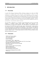
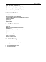
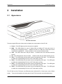
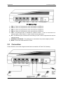
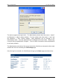
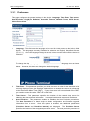
HT-342 User Manual
VoIP FXO Gateway
User Manual
Model: HT-342
Release 1.0
Table of Content
1
HT-342 User Manual
INTRODUCTION...................................................................................................................................... 1
1.1 OVERVIEW ......................................................................................................................................................1
1.2 PROTOCOLS .....................................................................................................................................................1
1.3 HARDWARE FEATURES..........................................................................................................................................2
1.4 SOFTWARE FEATURES ........................................................................................................................................2
1.5 LIST OF PACKAGE ..............................................................................................................................................2
2
INSTALLATION ....................................................................................................................................... 3
2.1 APPEARANCE ...................................................................................................................................................3
2.2 CONNECTION ...................................................................................................................................................4
3
WEB CONFIGURATION ......................................................................................................................... 6
3.1 ACCESS THE BUILT-IN WEB SERVER ......................................................................................................................6
3.2 STATUS..............................................................................................................................................................8
3.2.1 Phone Information .............................................................................................................................. 8
3.2.2
Network Information ........................................................................................................................ 8
3.3 CONFIGURATIONS .............................................................................................................................................8
3.3.1
Preference ........................................................................................................................................ 9
3.3.2
Network Configuration .................................................................................................................. 11
3.3.3
Call Settings ................................................................................................................................... 13
3.3.3.1
H.323 Phone ............................................................................................................................... 13
3.3.3.2
SIP Phone ................................................................................................................................... 18
3.3.3.3
Media Setting .............................................................................................................................. 22
3.3.3.4
Call divert .................................................................................................................................... 25
3.3.3.5
Save Configuration .................................................................................................................... 26
3.3.3.6
Discard Changes........................................................................................................................ 26
3.4 TOOLS ..........................................................................................................................................................26
3.4.1
Online Upgrade ............................................................................................................................. 27
3.4.2
Change Password ......................................................................................................................... 27
3.4.3
Reset Configuration ...................................................................................................................... 28
3.4.4
Reboot ............................................................................................................................................ 28
3.5
Dial Plan ............................................................................................................................................................. 28
3.6 GAIN SETTINGS… ...........................................................................................................................................30
Release 1.0
i
Introduction
1
1.1
HT-342 User Manual
Introduction
Overview
A VoIP FXO (Foreign Exchange Office) Gateway bridges the VoIP and PSTN
networks by enabling both voice and fax communications. It offers an FXO
interface to a traditional telephone line (PSTN) and an WAN Ethernet port interface
to the IP Network. A connection can be initiated either from a VoIP user to a PSTN
user or from a PSTN user to a VoIP user. It is a key component for building a hybrid
communication system with connections to both VoIP and PSTN networks. The key
advantage is to make use of the IP network and local PSTN networks to save on
international / long-distance phone expenses.
The HT-342 is designed as a compact, high performance, and low cost FXO
Gateway. It features superb audio quality, reliable FXO detection, rich
functionalities, and high-level integration. The FXO detection is optimized to avoid
the hold up of the PSTN line when the other party is disconnected. This has been
one of the key issues in the design of FXO gateway. The incoming PSTN Caller ID
is also transmitted to the VoIP user for more user friendly operation. The HT-342
is a full featured FXO gateway with a second Ethernet port for connection with
another network device. It is an ideal solution for VoIP to PSTN termination in both
SME and SOHO environment.
1.2
Protocols
TCP/IP V4 (IP V6 auto adapt)
ITU-T H.323 V4 Standard
H.225 V4 Standard
H.245 V7 Standard
H.235 Standard(MD5,HMAC-SHA1)
ITU-T G.711 Alaw/ULaw, G.729A, G.729AB, and G.723.1 Voice Codec
RFC1889 Real Time Data Transmission
Proprietary Firewall-Pass-Through Technology
SIP V2.0 Standard
Simple Traversal of UDP over NAT (STUN)
Web-base Management
PPP over Ethernet (PPPoE)
PPP Authentication Protocol (PAP)
Internet Control Message Protocol (ICMP)
TFTP Client
Release 1.0
1
HT-342 User Manual
Hyper Text Transfer Protocol (HTTP)
Dynamic Host Configuration Protocol (DHCP)
Domain Name System (DNS)
User account authentication using MD5
Out-band DTMF Relay: RFC 2833 and SIP Info
1.3 Hardware Features
ARM9E Processor for high performance
DSP for voice codec and voice processing
Two 10/100M Based Ethernet ports for WAN/LAN connections.
LED status indicators
One FXS port
Ethernet Bridge
1.4
Software Features
LINUX OS
Built-in HTTP for accessing internal parameters
PPPoE dial-up
Network Address Traversal (NAT) and Router functions
DHCP Client
DHCP Server
Firmware On-line upgrade
Phone Book
Caller ID (PSTN to VoIP)
Multiple Language Support
1.5
List of Package
The following items are included in the package.
1. One HT-342 main unit
2. One DC12V/500mA power adaptor
3. One Ethernet cable (3M)
Release 1.0
2
Installation
2
Installation
2.1
Appearance
HT-342 User Manual
HT-342 Front View
There are eight LEDs on the front panel to display the current status of the HT-342.
1) Power – This LED lights up when the power is applied.
2) RUN – This LED flashes at a rate of 100ms ON and 100ms OFF when the device is
booting up or connecting servers. It flashes at a rate of 1s ON and 1s OFF when server
connection is established. It does not flash or turn on when the device fails.
3) LAN – This LED shows the LAN port status. It flashes when link and data activities
occurs.
4) PC - This LED shows the PC port status. It flashes when link and data activities occurs.
5) FX01 – This LED shows the line status of the corresponding FXO port. The LED lights
up when the corresponding FXO line is OFF hook state (In Use).
6) FX02 – This LED shows the line status of the corresponding FXO port. The LED lights
up when the corresponding FXO line is OFF hook state (In Use).
7) FX03 – This LED shows the line status of the corresponding FXO port. The LED lights
up when the corresponding FXO line is OFF hook state (In Use).
8) FX04 – This LED shows the line status of the corresponding FXO port. The LED lights
up when the corresponding FXO line is OFF hook state (In Use).
The HT-342 has four FXO ports, two Ethernet ports (LAN and PC), Power Input, and a Reset
switch. They are all located at the back panel of the HT-342 as shown and described below.
Release 1.0
3
Installation
HT-342 User Manual
HT-342 Rear View
1)
2)
3)
4)
5)
FXO 1 - This is a FXO port and is to be connected to a PSTN line.
FXO 2 - This is a FXO port and is to be connected to a PSTN line.
FXO 3 - This is a FXO port and is to be connected to a PSTN line.
FXO 4 - This is a FXO port and is to be connected to a PSTN line.
LAN - This Ethernet port is intended for network access. It can be connected to a
network switch, xDSL modem, or other network access equipment.
6) PC - This Ethernet port is intended for connecting to a PC or other equipment that requires
network access.
7) POWER DC12V/500mA - This power jack is connected to the power adapter provided.
8) Reset - This is the reset switch for HT-342.
2.2
Connection
Please follow the connection diagram shown below to install the HT-342 FXO Gateway:
Release 1.0
4
Installation
1)
2)
3)
4)
5)
HT-342 User Manual
Connect a PSTN line to each FXO port (FXO1 and FXO2).
Connect an Ethernet cable (or the cable supplied) to the LAN port and the other end of the
cable is connect to an equipment with network access.
Connect the PC port to a PC or other equipment (Optional).
Connect analog phones to both Line1 and Line2 phone jacks.
Insert the adapter plug (provided) to the Power jack and then plug the adaptor to an AC wall
plug. PLEASE ONLY USE THE ADAPTER PROVIDED OR AN ADAPTOR WITH THE
SAME SPECIFICATION.
Release 1.0
5
Web Configuration
3
HT-342 User Manual
Web Configuration
The HT-342 can be configured via its built-in Web Server (HTML). To access this web
server, either the LAN IP or the PC IP must be known. The LAN port is pre-configured to
DHCP client mode and the PC port IP is set to 192.168.8.1.
3.1
Access the Built-in Web Server
The built-in Web Server can be accessed by typing the LAN / PC IP address in PC web
browser. Please see below to determine which IP Address to be used to access the built-in
Web Server.
Via the LAN port
1) A PC connected to the same network segment as the LAN port is available. Please note
that the PC port is in the same network segment as the LAN port if it is set to bridge
mode.
2) The LAN port IP address must be known. If the LAN port has a public IP to the internet,
any PC with internet access can access its built-in web server.
Via the PC Port
1) The PC port is pre-configured to the fixed IP address 192.168.8.1 and the DHCP server is
not enabled.
2) In this case, the PC connected to the same PC port network segment, the PC IP address
must be configured to an IP address that is in the same network segment. Please
consult the User Manual of your computer OS for configuring the PC IP address.
To access the built-in Web Server, type the correct IP address of the HT-342 in a Web Browser
(IE, Firefox, etc.) as shown below.
Once the device responds to the HTTP request, the Web Browser will prompt for a login window
as shown below.
Release 1.0
6
Web Configuration
HT-342 User Manual
The device supports two login levels. For Administrator, please enter User name = “admin”
and Password = “admin” (factory default). For User, please enter User name = “user” and
the Password = “1234” (factory default). Both passwords can be changed in the
Administrator mode. Only user password can be changed in the User mode. Please keep
a record of the new passwords if changed. There is a Star Command to reset the passwords
to the factory defaults.
The Administrator mode allows full access to the built-in Web Server whereas the User mode
restricts the user from accessing the Call Settings page.
Once the login is successful, the Web Browser brings up the Status page as shown below.
Release 1.0
7
Web Configuration
HT-342 User Manual
3.2 Status
The Status page shows the current status, hardware and software information of the HT-342.
3.2.1 Phone Information
1
2
3
4
Serial Number
Each device is assigned with a unique serial number by the factory. This number is
important for auto provision, technical support, and warranty repair. The product label at
the bottom also contains this information.
Firmware Version
This field identifies the current Firmware Version installed.
Hardware Model
This field identifies the hardware model and version.
Phone Status
This field shows the status of server registration for each FXS port. If the device registers
to the designated server(s) successfully, it displays the status “LOGIN”. Otherwise, it
displays “LOGOUT”
3.2.2 Network Information
1
2
3
LAN Port
This field shows IP address assigned to the LAN port.
LAN MAC
This field shows the MAC address assigned to the LAN port.
PC Port
This field shows IP address assigned to the PC port.
4 PPPoE
5
6
3.3
This field shows the dial up status when PPPoE is enabled for ADSL login.
Default Route
The Default Route shows the IP address of the default gateway / router that is used in the
current network environment.
DNS Server
This field shows the IP address of the DNS server to be used for domain name
interpretation.
Configurations
To access the Configurations page, click on the “Configurations” tab on the left hand column.
This brings up all the pages under this tab: Preference, Network, Call Settings, and Phone
Settings.
Release 1.0
8
Web Configuration
HT-342 User Manual
3.3.1 Preference
This page configures the general settings in the device: Language, Time Zone, Time server,
Auto-Provision, Key(#) as Delimiter, Auto-dial Timeout, Network Tones, INFO Server,
China Phone Code.
1
Language - This field sets the language to be used for initial access to the built-in Web
Server. The languages currently available for selection are English, Simplified Chinese
(简体中文). Once the language change is saved, it does not take effect until the device is
rebooted.
To change the display language immediately, you can select the language icon as shown
below. However, this does not change the default language.
2
3
4
Time Zone – This parameter specifies your local time zone in order for the date/time to be
correctly displayed since the date/time obtained from a network time server is referenced
to the Greenwich Mean Time (GMT). If your time zone is 8 hours ahead of the GMT,
you need to enter the value “GMT+8” in this field.
Time Server – This parameter specifies the location of the network time server for
obtaining the date and time information. It accepts both domain name and IP address.
Auto Provision – This parameter enables or disables the Auto Provision procedures.
The Auto Provision is a batch script to obtain configuration and firmware upgrade
information from a server. Once this option is enabled, two additional parameters
(Provision Server and Provision Interval) are displayed. The Provision Server
specifies the location of the designated provision server. The auto provision procedure is
Release 1.0
9
Web Configuration
HT-342 User Manual
executed at boot up time and is repeated at a duration specified in the parameter
Provision Interval.
5
Network Tones – This parameter defines the network tones to be used. The predefined
networks tones are: China, Hong Kong, Taiwan, New Zealand, United Kingdom,
United States, Korea, Slovenia, Czechoslovakia, India, Singapore, Israel, Malaysia,
Indonesia, Thailand, Romania, Bangladesh, and Customized. The Customized
option allows user to define his own network tones. If the desired network tones selection
is not available, user can use this Customized option.
Each network tone is defined as
nc, rpt, c1on, c1off, c2on, c2off, c3on, c3off, f1, f2, f3, f4, p1, p2, p3, p4
where
nc is the number of cadences
rpt is the repeat counter(0 - infinite, 1~n - repeat 1~n times)
c1on is the cadence one on duration (in milliseconds)
c1off is cadence one off duration (in milliseconds)
c2on is the cadence two on duration (in milliseconds)
c2off is the cadence two off duration (in milliseconds)
c3on is the cadence three on duration (in milliseconds)
c3off is the cadence three off duration (in milliseconds)
f1 is the tone #1, 300-3000(Hz)
f2 is the tone #2, 300-3000(Hz)
f3 is the tone #3, 300-3000(Hz)
f4 is the tone 34, 300-3000(Hz)
p1 is the attenuation index for tone #1, 0~31(0=3dB, -1dB increments)
p2 is the attenuation index for tone #2, 0~31(0=3dB, -1dB increments)
p3 is the attenuation index for tone #3, 0~31(0=3dB, -1dB increments)
p4 is the attenuation index for tone #4, 0~31(0=3dB, -1dB increments)
Two network tone definition samples are shown below.
1.
A New Zealand Dial Tone (400 Hz) is defined as 0,0,0,0,0,0,0,0,400,0,0,0,10,0,0,0.
2.
A New Zealand Busy tone (400Hz with a cadence of 500ms on and 500ms off (repeat)) is
Release 1.0
10
Web Configuration
HT-342 User Manual
defined as 1,0,500,500,0,0,0,0,400,0,0,0,10,0,0,0.
6
PSTN Has Line Reversal – When this parameter is enabled, the HT-342 enables the fast
start channel in H.323 or the Early Media channel in SIP to monitor when the called party
answers the call. This feature is commonly used to achieve more accurate billings for
calls to the PSTN line.
3.3.2 Network Configuration
This page configures the network interface for LAN Port and PC Port.
LAN Port – The LAN port is intended for internet access. It is normally connected to a network
device (router or ADSL modem) which has internet access. The following 3 modes are
available for selection.
1.
2.
DHCP – This mode should be selected If the network device functions as a DHCP host,
This allows the DEVICE to obtain all related network information / settings from the DHCP
host.
Static IP – This mode sets the LAN port IP manually which can either be a public or
private IP. Other network settings (Subnet Mask, Default Route, Primary DNS,
Secondary DNS) should also be entered accordingly.
Release 1.0
11
Web Configuration
3.
HT-342 User Manual
PPPoE – This selection is intended for broadband connection (ADSL / Cable modem) that
requires dial up / authentication using PPPoE protocol. Both User Name and Password
are required. Please consult your service provider for more information if needed. One
advantage with the PPPoE dial up is that the IP address obtained for the LAN port is
normally a public IP.
More advanced parameters for 802.1q VLAN and MAC settings are available. Please consult
your network administrator for assistance if needed.
PC PORT – The PC port is intended to provide an Ethernet connection to other network devices
(for example: PC, network HUB.). Two modes of operation are available:
1.
Bridge mode - This mode allows the network traffics at the PC port to be bypassed to LAN
port. This means that the network device share the same network segment as the LAN
port. There is no IP address assigned to the PC port.
2.
Fixed IP - This mode sets the PC port IP Addresss (private IP) and Subnet Mask
manually. This creates a new network segment for the network devices connected to the
PC Port.
To simplify network IP assignments, enable the DHCP Server for the PC Port. This
allows network devices connected Port to obtain network IP and related information from
the PC Port. Please consult your network administrator for proper settings of the DHCP
Server
Release 1.0
12
Web Configuration
3.3.3
HT-342 User Manual
Call Settings
This page configures all related settings for VoIP Service. Based on the two protocols (H.323
and SIP) supported, the operation of DEVICE is divided as two Endpoint Types: H.323 Phone
and SIP Phone. Some of the parameters are unique to the Endpoint Type and are described
separately below.
3.3.3.1 H.323 Phone
The H.323 Phone selection for Endpoint Type refers to the protocol used. The basic H.323
settings are:
1.
Endpoint Mode – Gatekeeper Mode supports VoIP calling via a call server. Server
Registration is required. Direct Mode supports making a VoIP call by dialing the IP
addresses or an alias. Server Registration is not required.
Release 1.0
13
Web Configuration
2.
HT-342 User Manual
Config Mode – The device supports two modes: Single Config, Config by Line and
Config by Group.
Single Config offers only one phone number and Gatekeeper configuration for both FXO
lines.
Config by Line allows each FXO line to have its own configuration of the following
parameters: phone number, H.323 ID, Gatekeeper Address, Signaling Encryption method,
H.235 Auth., Dial Plan, and Fax Line.
Config by Group allows up to 4 configuration groups for the two FXO lines. Each
configuration group includes the following parameters: phone number, H.323 ID,
Gatekeeper Address, GateWay Prefix, Signaling Encryption method, H.235 Auth., Dial
Plan, Activated Lines and Fax Line. The Line Parameter specifies which FXO lines are
Release 1.0
14
Web Configuration
HT-342 User Manual
included in the group. Each FXO line can be assigned to any of the groups.
3.
4.
5.
6.
7.
8.
9.
Phone Number - This parameter assigns the phone number used for registration in
Gatekeeper Mode. This is used as an alias in Direct Mode.
Display Name – This parameter (optional) specifies the Caller name and is transmitted as
part of the caller ID.
H.323 ID - This parameter is specified in the H.323 protocol. It is an identifier containing
an alphanumeric string. Some gatekeepers may use this ID for authentication.
GateWay Prefix – This assigns a prefix for routing PSTN calls via the HT-342
automatically. Dial the prefix and then a PSTN number will result the call to be routed and
dialed out via the corresponding FXO port.
Gatekeeper Address - This assigns the location of the Gatekeeper for VoIP Service.
VOS/AVS Signaling Encryption – Both VOS2000 / AVS Encryption methods are used by
major network equipment vendors in China to avoid VoIP blocking in order insure a reliable
VoIP services. In order to use this, your VoIP service provider needs to support this
encryption method. For H.323, VOS / AVS Encryption can be enabled or disabled for
each number registration. VOS Encryption supports two modes: Signaling Encryption
and Signaling and Media Encryption. Please consult your services provider for more
information.
Authentication – If H.235 authentication is required, enable this field and enter the H.235
ID and Password.
Release 1.0
15
Web Configuration
10.
11.
12.
HT-342 User Manual
Dial Plan – This defines the dialing rule when making PSTN calls.
Activate Lines in Group X – This section specifies the FXO lines to be used in the Group.
Fax Line – Enable the support of FAX function for the line selected.
Advanced Settings
More settings are available under the Advanced Settings tab. These settings are common to
all H.323 configurations. Depending on your network requirements, please consult your
network administrator for the correct configuration.
1.
2.
3.
4.
5.
RAS Port – This Port is used to convey the registration, admissions, bandwidth change,
and status messages between two H.323 endpoints. If not specified, the port address is
assigned automatically.
Q.931 Port – This port is used for call signaling to convey Call Setup and teardown
messages between two H.323 endpoints. If not specified, the port address is assigned
automatically.
H.245 Port – The H.245 requires at least 2 ports for media control protocol. It should be
specified as a port range. If not specified, the port address is assigned automatically.
Fast Start - Fast Start is a new method of call setup that bypasses some usual steps in order to
make it faster. In addition to the speed improvement, Fast Start allows the media channels to be
operational before the CONNECT message is sent, which is a requirement for certain billing
procedures. Leave this enabled if you are not sure.
Register Mode - Two registration modes are support. Register Multiple Numbers
mode means that multiple numbers are registered in a single registration message.
Release 1.0
16
Web Configuration
HT-342 User Manual
Register Multiple Times mode means that each number is registered in a separate
registration message.
6.
DTMF Signaling – This parameter sets the method of sending DTMF signals. Inband
measns that the DTMF signal is sent as an analog signal via the voice channel. Outband
means that the DTMF signal is sent as DTMF command via the data channel and is
commonly known as RFC2833. In Outband mode, a DTMF payload type is required and
the default type is set to 101.
7.
Signaling QoS – This parameter sets the QoS mode for VoIP Signaling for better
response time and more reliable VoIP Call signaling. Both IP TOS and Diffserv modes
are supported. Please check with your network administrator or ISP for the correct
setting.
8.
Signaling NAT Traversal – NAT Traversal is an algorithm designed to solve a common
problem in TCP/IP networking in establishing connections between hosts in private TCP/IP
networks that use NAT devices. This parameter only sets the NAT Traversal mode for
VoIP signaling. The 3 methods supported are NAT Citron, Port-forward/DMZ, and
Relay Proxy.
Both NAT Citron and Port-forward/DMZ are well known NAT protocols are are widely
used; however, they require the support of local network.
Relay Proxy mode is a proprietary NAT protocol and it is designed for NAT Traversal with
the capability of avoiding VoIP blockings. All VoIP signaling and/or media packets are
encapsulated (encrypted as well if enabled) and transmitted via another port/channel to
our proprietary Relay Server. Please contact your service provider to determine if this
mode is supported.
Release 1.0
17
Web Configuration
HT-342 User Manual
Relay Proxy mode is a proprietary NAT protocol and it requires the use of our Relay Proxy
Server. All VoIP signaling packets are encapsulated (encrypted for more secured
transmission if enabled) and transmitted via another port/channel. Up to 4 backup Relay
Servers are supported. Once the designated Relay Server fails, the next available Relay
Server on the back up list will be used. Once the designated Relay Server resumes
operation, it will be used instead of the back up Relay Server.
Note:
For Service providers, RELAY Proxy software is available at no charge.
supplier for support.
Please contact your
For end user, please contact your service provider to see if this feature is available.
3.3.3.2 SIP Phone
The SIP Phone selection for Endpoint Type refers to the SIP protocol used.
1.
Config Mode – The device supports two modes: Single Server Mode and Config by Line..
Single Server mode - only one SIP registration is used for both FXO lines. The HT-342
performs line hunting automatically when a call is made to the PSTN lines.
Release 1.0
18
Web Configuration
HT-342 User Manual
Config by Line - each FXO line has its own SIP registration and they are treated as
independent lines. .A Backup Server option is also available for each FXO line to insure a
more reliable SIP Service.
2.
3.
4.
5.
6.
7.
8.
Phone Number – This sets the phone number to be used in SIP registration and calls.
Phone Number 2 – A second number can be assigned for second SIP registration.
Display Name – This assigns the name to be used in the Caller ID name delivery.
SIP Proxy – This sets the SIP proxy in either IP Address or domain name format. The
standard port used for SIP signaling is 5060. To specify a different port add “:” (colon) after
the SIP Proxy address and then the desired port number. (e.g. sip.at338.com:5070).
SIP Registrar Server - This sets the SIP Registration Server either IP Address or domain
name format. If this is blank, the SIP Proxy will be used for registration. The standard
port used for SIP signaling is 5060. To specify a different port add “:” (colon) after the SIP
Proxy address and then the desired port number. (e.g. sip.at338.com:5070).
Register Expiry(s) – This sets the registration period.
Outbound Proxy – An Outbound proxy is mostly used in presence of a firewall/NAT to handle
the signaling and media traffic across the firewall.
If the SIP proxy can handle NAT or has a
built-in outbound proxy, this field can be set to the same address as the SIP proxy or left blank.
In some cases, the outbound proxy (referred as Outbound Session Controller) is placed
alongside the firewall and is the only way to let SIP traffic pass from the internal network to the
Internet. In these cases, the Outbound Proxy must be set properly in order to ensure normal
Release 1.0
19
Web Configuration
HT-342 User Manual
SIP operation.
9.
10.
11.
12.
13.
14.
Home Domain – This sets the domain name for providing service to a SIP user. Typically,
this is the domain present in the URI in the address-of-record of a registration.
Authentication ID – This is used for authentication during registration. Very often, the
Phone Number is used as Authentication ID.
Password – This field specifies the password for authentication.
Call Forward Type – This sets the type of Call Forwarding modes:
Call Forward Number – This sets the number to be used in Call Forwarding
Backup Server - When system support backup server fill in the messages of the backup
server. When the first server is failed HT-342 will try the backup server.
Advanced Settings
More settings are available under the Advanced Settings tab. Depending on your network
requirements, please consult your network administrator for the correct configuration.
1.
2.
3.
4.
5.
Signaling Port – This Port is used to convey signaling message with the SIP Proxy. The
standard port number is 5060.
NAT Keep-alive – When enabled, a dummy packet I sent to the local firewall / router in
order to keep the ports opened for VoIP service.
P2P – This enables Peer-to-Peer calls.
Virtual Ringback – This enables a ringback tone to be generated whenever a call is made.
DTMF Signaling – This parameter sets the method of sending DTMF signals. Inband
measns that the DTMF signal is sent as an analog signal via the voice channel. Outband
Release 1.0
20
Web Configuration
HT-342 User Manual
means that the DTMF signal is sent as DTMF command via the data channel. Both
RFC2833 and SIP INFO methods are supported. For RFC2833, a DTMF payload type is
required and the default type is set to 101.
6.
Signaling QoS – This parameter sets the QoS mode for VoIP Signaling for better response
time and more reliable VoIP Call signaling. Both IP TOS and Diffserv modes are supported.
Please check with your network administrator or ISP for the correct setting.
7.
Signaling Encryption – Five types of encryption methods are supported and these are
used by various network equipment vendors in China to avoid blocking of SIP signaling
traffics. Please consult your SIP service provided to determine which encryption method is
supported.
a)
b)
c)
d)
e)
8.
RC4 – RC4 Encryption Key is required when it is enabled.
Fast –
VOS – This encryption is developed by a network equipment vendor in Nanjing, China.
AVS – This encryption is developed by a network equipment vendor in Shanghai, China.
ET263 – This encryption is supported by major network equipment vendors in China.
Signaling NAT Traversal – NAT Traversal is an algorithm designed to solve a common
problem in TCP/IP networking in establishing connections between hosts in private TCP/IP
networks that use NAT devices. This parameter only sets the NAT Traversal mode for VoIP
signaling. The 2 methods supported are STUN(RFC3489) and Relay Proxy. A STUN
Server is required for STUN(RFC3489).
Release 1.0
21
Web Configuration
HT-342 User Manual
Relay Proxy mode is a proprietary NAT protocol and it requires the use of our Relay Proxy
Server. All VoIP signaling packets are encapsulated (encrypted for more secured
transmission if enabled) and transmitted via another port/channel. Up to 4 backup Relay
Servers are supported. Once the designated Relay Server fails, the next available Relay
Server on the back up list will be used. Once the designated Relay Server resumes
operation, it will be used instead of the back up Relay Server.
Note:
For Service providers, RELAY Proxy software is available at no charge.
supplier for support.
Please contact your
For end user, please contact your service provider to see if this feature is available.
3.3.3.3 Media Setting
Once a VoIP call is established, the Media channel is used for voice transmission. The settings
listed below configure the performance and operation of the Media channel.
1.
2.
3.
RTP Port (range) – Audio stream is transmitted via Real Time Protocol (RTP) and at least
4 ports are used per voice channel. The default port range is 16384 – 32768. Specify
the port range depending on your network environment if needed.
Packet length (ms) – This specify the length of a voice packet. The default packet
length is 20 ms.
Jitter Buffer Mode –Three jitter modes are available. The Fixed Mode, which is the
default mode, is a simple first in first out mode, with a fixed jitter buffer delay. By
definition the jitter buffer depth is twice the jitter buffer delay. The Sequential Mode is
also a fixed jitter buffer delay mode, but in this mode the jitter buffer function looks at
the packet timestamp for dropped or out of sequence packet problems. The data
packets are sorted based on the packet timestamp. The Adaptive Mode optimizes the
size of the jitter buffer delay and depth in response to network conditions, in addition to
the sequential mode.
Release 1.0
22
Web Configuration
4.
HT-342 User Manual
Media QoS – QoS is also available for Media packets to improve voice quality. This is
rather significant in a network environment with large amount of data traffics. Both IP
TOS and DiffServ methods are supported.
5. Media Encryption – For secure voice transmission, RC4 / ET263 Encryption methods are
supported for the media channel. Please make sure your service provider can support this
encryption method before enabling this feature.
6. Symmetric RTP – Enable the media channel to use symmetric RTP ports. Some network
environment demand the use of Symmetric RTP.
7. Media NAT Traversal – NAT Traversal can be set independently for Media packets. This
gives a more flexible setting for various network environment. Three modes are supported:
STUN(RFC 3489), Port-forward/DMZ, and Relay Proxy.
8. Relay Proxy mode is a proprietary NAT protocol and it requires the use of our Relay Proxy
Server. All VoIP signaling packets are encapsulated (encrypted for more secured
transmissions if enabled) and transmitted via another port/channel. Three relay modes of
operation are supported.
Mode 1: Use UDP packets and encryption.
Mode 2: Use UDP packets and encryption; use single UDP port.
Mode 3: Use TCP packets and encryption; Use single TCP port;
The mode 2 and mode 3 are the passive and the port use is assigned by the RELAY
SERVER.
Up to 4 backup Relay Servers are supported. Once the designated Relay Server fails, the
next available Relay Server on the back up list will be used. Once the designated Relay
Server resumes operation, it will be used instead of the back up Relay Server.
Release 1.0
23
Web Configuration
HT-342 User Manual
Note: For Service providers, RELAY Proxy software is available at no charge. Please
contact your supplier for support. For end user, please contact your service provider to see
if this feature is available.
9. Audio Codec Preference – The table below list the voice codec priorities in descending
order. Each voice codec can be enabled (place a check mark in the check box) or disabled
individually. Select the voice code and then click on the UP or DOWN button to move the
order on the list.
Release 1.0
24
Web Configuration
3.3.3.4
HT-342 User Manual
Call divert
This page sets the call routing to and from the PSTN lines. Each line has its own settings.
Select the line desired and then program the parameters below.
1.
2.
3.
4.
5.
6.
7.
Forward to PSTN – This enables or disables calls to be forwarded to the PSTN line.
When it is set to disabled, no VoIP calls are routed to the PSTN line 1. When it is enabled,
VoIP calls are forwarded to the PSTN line according the following 3 parameters.
Forward Number (VoIP to PSTN) – When a PSTN number is assigned, VoIP calls are
forwarded to PSTN via the corresponding line automatically. When a comma (“,”) is
inserted in this number, a dialing pause of 500 ms is inserted when dialing the number to the
PSTN line.
Forward Password (VoIP to PSTN) – When it is set, the forward password from VoIP to
PSTN feature is enabled. When a VoIP caller is trying to access the PSTN line, an
indication tone is first generated to prompt the caller to dial the password. Once the correct
password is dialed, the PSTN line is connected and the caller can then hears the PSTN dial
tone. If Forward Number (VoIP to PSTN) is set, the number will then be dialed out
automatically.
Dial Plan (VoIP to PSTN) – Please refers section 3.3.5 for more information.
Forward to VoIP – This enabled incoming PSTN calls to be routed to the VoIP network.
When it is disabled, no incoming PSTN calls are accepted. When it is enabled, incoming
PSTN calls are first answered and then processed according to the 3 parameters below.
Forward Number (PSTN to VoIP) – When a VoIP number is assigned here, incoming
PSTN calls are forwarded to VoIP number automatically.
Forward Password (PSTN to VoIP) - When it is set, the forward password from PSTN to
VoIP feature is enabled. When an incoming PSTN call is answered, an indication tone is
generated to prompt the user to enter the forward password entered in this field. Once the
Release 1.0
25
Web Configuration
8.
9.
HT-342 User Manual
correct password is entered, a VoIP dial tone is generated to allow making a VoIP call. If the
Forward Number (PSTN to VoIP) is set, this number is dialing out automatically.
Dial Plan (PSTN to VoIP) – Please refer section 3.3.5 for more information.
VoIP Auto Answer Time (s) – This sets the waiting time before answering an incoming
PSTN call.
3.3.3.5
Save Configuration
Once a change is confirm, users should click on the “Save Configuration” button in the
Configuration page. Otherwise, your configuration will not take effect. After user click the “Save
configuration” the screen will be:
3.3.3.6
3.4
Discard Changes
Tools
The Tools section is intended to offer the following functions: Online Upgrade, Change Password, Reset
Config, and Reboot.
Release 1.0
26
Web Configuration
HT-342 User Manual
3.4.1 Online Upgrade
Click on the Online Upgrade tab to perform manual firmware upgrade. Enter the upgrade address as
shown below. Please contact your service provider to determine if there is a new firmware available.
WARNING: Once the upgrade starts, a message window is display to show the upgrade
status. DO NOT TURN OFF THE POWER WHILE THE FIRMWARE UPGRADE IS IN
PROCESS!
3.4.2 Change Password
The device supports two login levels to the built-in webpage. The User level is intended for
general user and is restricted from accessing the Call Settings page and Reset Configuration
function. In this level, only the password for the user level can be changed. The default
password for the user level (login ID = user) is “1234”.
The Administrator level allows full accessing to the DEVICE configurations. In this level, the
password for both levels can be change. The default password for the administrator level (login
ID = admin) is “admin”.
It is important to record the new password(s). If the admin password is lost, a special star
command is available to reset all system settings. Please refer to section 3.1.1 for more
information.
Release 1.0
27
Web Configuration
HT-342 User Manual
3.4.3 Reset Configuration
This function can only be accessed in administrator login level. Click on the Reset
Configuration tab to initiate the reset process. A message windows pops up to ask for
confirmation. Click “Yes” to reset all configurations back factory defaults. Click “No” to cancel.
Once the reset process is completed, the device reboots itself.
Please also see section 3.1.1 for a star command reset option.
3.4.4 Reboot
Click on the Reboot tab to reboot the device.
3.5
Dial Plan
Dial Plan defines how the DEVICE processes a number when it is dialed. This field is located
in the Calling Setting Window and it is available for both H.323 and SIP modes. The Dial Plan
is very flexible and can be configured for a wide range of dialing applications.
Release 1.0
28
Web Configuration
HT-342 User Manual
The basic syntax is “<event>:<action>|<event>:<action>|…”, where
<event> defines the event to be matched. A event consists of a sequence of digits. If a
specific digit has a limited range, use the syntax [A-B] where A and B are both digit (0
to 9) and B is greater than A. The length of the input number can be limited by using
“X” to represent each unknown digit. If this field is omitted, it means any event.
<action> defines the action to be taken on the number received and it consists of “–“ (minus), “+”
(plus), and digits. “-“ followed by digits means to remove the digits from the beginning
of the number entered. “+” followed by digits means to add the digits in front of the
number entered.
“|” means or and the order of priority is from left to right.
Note: For practical use, it should not be possible to reach the maximum length of the Dial Plan
string.
Examples:
1.
Dial Plan = “010:-010” means that the number dialed out will have the first 3 digits ”010”
removed when a number with the first digits as “010” is entered.
a) Number entered = “01082121234”, actual number dialed = “82121234”.
b) Number entered = “82121234”, actual number dialed = “82121234”.
2.
Dial Plan = “1:+00” means that the number dialed out will have the “00” added in front of
the number entered when a number with the first digit as “1” is entered,.
a) Number entered = “1082121234”, actual number dialed = “00182121234”.
b) Number entered = “82121234”, actual number dialed = “82121234”.
3.
Dial Plan = “001:-001+1751” means that the number dialed out will the first 3 digits “001”
changed to “1751” when a number with the first digits as “001” is entered.
a) Number entered = “00182121234”, actual number dialed = “175282121234”.
b) Number entered = “82121234”, actual number dialed = “82121234”.
4.
Dial Plan = “XXXX:” means that the input number is limited to 4-digit long and will be
dialed out immediately when the fourth digit is entered.
5.
Dial Plan = “13XXXXXXXXX:+0” means that the input number is restricted to 11-digit long
and the first two digits must be “13”. When this condition is matched, the number dialed
out will have a leading “0” added.
a) Number entered = “13901234567”, actual number dialed = “013901234567”.
b) Number entered = “12801234567”, actual number dialed = “12801234567”.
6.
Dial Plan = “13[6-9]XXXXXXXX:+0” means that the input number is restricted to 11-digit
long and the first two digits must be “13” and the third digit can be 6, 7, 8,or 9. When this
condition is matched, the number dialed out will have a leading “0” added.
a) Number entered = “13901234567”, actual number dialed = “013971234567”.
Release 1.0
29
Web Configuration
b)
HT-342 User Manual
Number entered = “13001234567”, actual number dialed = “13001234567”.
Please note that the above samples are simple and intended to show the meaning of various
rules. They may not have any practical meaning. A combination of these rules (joined with
the symbol “|”) can be realized for a much more complicated dialing application.
3.6
Gain Settings…
The gain setting must be cautious to using. It was a hidden web page. If you want adjust the VoIP
Lines’s volume. Please rewrite the URL address to http://xxx.xxx.xxx.xxx/default/en_US/gain.html
and enter. The web browser will show up a GAIN SETTINGS screen.
You can adjust the volume of the two PSTN Lines to different values. The range you can adjust is
from 5 to -5.
Note: A too low or too high input gain will make DTMF detector insensitive.
Release 1.0
30