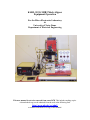
1
KARL SUSS MJB3 Mask Aligner
Equipment Operation
For the Micro-Electronics Laboratory
At
University of Notre Dame
Department of Electrical Engineering
This user manual is not to be removed from room 247B. This includes making copies.
A downloaded copy can be obtained from the web at the following link:
http://www.nd.edu/~ee/ndnf/
or contact Keith Darr for a copy of this manual.
Purpose
The MJB3, located in room 247B, offers front side illumination for contact
photolithography. The aligner is equipped with a 350W mercury lamp, and provided a
typical intensity of approximately 20mW/cm2 at 405 nm.
Reference
Karl Suss MJB 3 Mask Aligner Operator’s Reference Manual
Constant Intensity Controller Manual
Additional Equipment Required
Light Intensity Meter Model #1000
Materials Required
Photoresist coated samples
4” contact mask (100mm X 100mm)
Protective Equipment Required
Latex Gloves
Safety glasses
It is acceptable to remove safety glasses for alignments to allow proper use of the
microscope.
Engineering and/or Administrative Controls
Only authorized users may operate this piece of equipment
Training
To obtain training on this machine, please contact Keith Darr (office 221, phone
1-5497, email [email protected])
Problems
For problems, clarification of procedures, or general information pertaining to this
machine please contact one of the following personnel.
Keith Darr 631-5497
[email protected]
Mike Thomas 631-7493
[email protected]
Mark Richmond 631-6478 [email protected]
In Case of Emergency, Please Contact Notre Dame Security at
911
MSDS’s can be located in the EE Department office or in Room 244 near the door
Keith Darr
Rev 2.0
11/3/2008
2
Table of Contents
Page
4
5,6
7
8
9
10,11
12
12
13
Contents
Standby Conditions, Preparation
Start up procedure
Loading a Mask, Microscope Setup
Exposure Mode Options and Chuck Selection
Loading a Sample, setting the Contact Height
Alignment
Exposure
Unloading the Substrate and Completing Operation
Appendix
Note: All Figures are contained in the Appendix
Keith Darr
Rev 2.0
11/3/2008
3
Standby Conditions
1. X and Y micrometer fine travel to MIDRANGE position. (figure 1)
2. Contact lever is rotated to the FRONT of the machine (figure 7)
3. Separation lever is towards the BACK of the machine (figure 7)
4. Z micrometer should be locked in place (figure 8)
5. The chuck platform slid OUT to the right
6. Air and Nitrogen ON (figure 2)
7. Lamp Power Supply ON (figure 3)
8. Karl Suss Power ON (figure 4)
9. Reticle Holder on table with Dummy Reticle attached and face up
10. Microscope illumination ON
a. DO NOT Adjust higher than #5 on the right side unit.
11. Dosimeter OFF and on the shelf to the left of Karl Suss #1
Preparation
1. Apply and bake Photoresist as per user process.
2. The following steps are OPTIONAL, as they may not be appropriate for all
processes.
a. Remove any resist from the back of the sample so the wafer is flat on the
chuck and does not contaminate the chuck.
i. Dampen a wipe with acetone and gently slide the sample across
b. Mask Clean
i. Working in a wet bench, Holding the edge of the reticle
ii. Spray reticle with ACETONE
iii. Methanol
iv. Blow dry with N2
Keith Darr
Rev 2.0
11/3/2008
4
Start Up Procedure
1.
2.
3.
4.
5.
6.
7.
8.
9.
Check the logbook to make sure the last user has logged out.
Read the log book comments of previous users to verify the machine condition.
Log In to the log book.
If the UV lamp is off:
a. Ensure the power to Karl Suss MJB-3 is OFF before firing the lamp
NOTE: Starting the lamp with the unit powered on may cause
coupling of RF power and damage to the machine.
b. Verify the exposure lamp power supply is powered ON (Figure 3)
a. Wait until the display reads “rdy” (Ready).
On the lamp power supply, press and release the start button to start the lamp
a. If the lamp does not light, wait 1 minute and repeat
b. If the lamp does not start after 9 tries, stop. Contact lab staff.
When the lamp ignites, the display will read “COLD” for about 3 minutes, after
which the lamp wattage will be displayed.
Change the Lamp Power Supply mode to the constant intensity mode (CI2 lit)
a. 15 minutes after lamp has been lit, the power output will have stabilized
Power on the Karl Suss (MJB3) by pressing the red power button on the control
panel
Turn on the microscope illumination “White Light” control
a. This illuminates the sample through the microscope optics for alignment.
NOTE: The light is filtered and will not cause photoresist exposure
Keith Darr
Rev 2.0
11/3/2008
5
Dose Reading
1. Set the exposure timer as per the section below to a value of 30 seconds.
2. Place the machine in “Soft Contact” mode
3. Turn on the Light Intensity Meter
a. Handle the sensor by the black body of the sensor, not by the wire
4. Place the sensor underneath the microscope in the center of the exposure area.
5. Move the Contact lever to the 180° position
a. This will raise the sensor and apply a vacuum holding the sensor in place
6. Press the Exposure button on the Karl Suss
a. The microscope will lift and move forward over the sensor
7. Read and record in the log book, the Light Intensity Meter reading while the
shutter is open
8. When the microscope has returned to the original position, lower the sensor by
rotating the contact lever
a. The vacuum will release and you may remove the sensor
9. Turn off the Light Intensity Meter and return it to the shelf
Calculate the required Time and Set the Timer
1. Formula for calculating the required time for exposure
a. Required exposure time = required dose / light intensity
b. The user will need to establish the required time and adjust it as necessary
depending on their results. This will vary depending on the temperature
and humidity of the lab, the thickness and the type of resist being used,
and the desired process.
2. Set the exposure timer located on the right end of the front panel
a. Timer multiplier “s, 10s, 10m, h, 10h”
i. Align with the small “►” mark on the timer face plate
b. [With a timer pointer which increments from 0-3]
i. The timer has a range between 0.1 seconds to 30 hours
c. Examples:
i. To set exposure time of 2 seconds
1. Set timer pointer at “2” and multiplier at “s”
ii. To set exposure time of 8 minutes
1. Set timer pointer to “0.8” and multiplier to “10m”
Keith Darr
Rev 2.0
11/3/2008
6
Loading A Mask
NOTE: It is important NOT to scratch the chuck or the mask holder. This will cause
vacuum failure. Use only Teflon tweezers on wafer chuck.
1. With the mask holder on a flat surface and the “protection reticle” facing up, push
the mask vacuum button on the front panel to the “Off” position.
2. Remove the “protection reticle” and set it aside.
3. Inspect the vacuum ring for nicks and particulates.
4. Center your mask on the on mask holder, chromium side up, and align the mask
to be parallel to the edges of the mask holder as best as you can.
5. Press the mask vacuum button to fix the mask to the mask holder by vacuum.
6. Carefully check that the vacuum is holding the mask plate by trying to move it.
7. Pick up the mask holder up, turn it over, and insert it into the stage. (Figure 5)
8. Clamp the mask holder in place by tightening the two knobs finger tight. Do not
over tighten. (Figure 6)
Microscope Setup
1. To focus the microscope
a. First view through the right eyepiece and focus the microscope on a
feature on your reticle
2. Then correct the image sharpness for the left eye by turning the focus ring of that
eyepiece. (Figure 9)
a. If the eyepieces are too close or two far away from each other, the distance
may be adjusted by sliding the lenses in the correct direction.
Keith Darr
Rev 2.0
11/3/2008
7
Exposure Mode Options and Chuck Selection
1. Select the exposure mode desired (HP, ST, or soft contact) on the control panel
a. High Pressure vacuum contact mode.
i. Only chucks with vacuum gaskets must be used in this mode.
1. A vacuum between the substrate and the mask is switched
on during exposure to increase the contact pressure
ii. When printing in the vacuum contact mode. The following
sequence of events occurs:
1. The vacuum under the substrate is switched off when the
sample is moved to the contact position.
2. When the vacuum chamber or exposure buttons are
pressed, the space between the mask and sample is
evacuated, leading to increased contact pressure.
Note:
If the sample/mask contact is poor, the
sudden evacuation of the vacuum chamber
can lead to motion of the sample
(misalignment) or even sample breakage.
3. The vacuum level on the vacuum gauge should read “-.6”
a. The needle valve generally need not be adjusted,
except under unusual circumstances.
4. When the separation or the contact lever is used to lower
the sample, the vacuum is turned off and nitrogen is
turned on to break the vacuum between the substrate and
the mask.
b. Standard mode(ST) and soft contact
i. Only chucks without vacuum gaskets should be used in the ST
mode of operation.
ii. In the ST mode, one of two (standard or soft contact) exposure
programs can be selected on the control panel.
1. During Soft Contact (light on) the vacuum under the
sample remains on during exposure
2. During Standard Contact (soft contact light off) nitrogen
pressure presses the sample against the mask during
exposure, improving sample contact.
Keith Darr
Rev 2.0
11/3/2008
8
Loading a Sample, setting the Contact height
1. Inspect chuck surface. There should not be any nicks or debris.
2. Place the substrate on the chuck so it covers all the open vacuum holes.
a. Certain chucks have been modified to allow the use of small samples. If
the chuck is turned upside down, the operator will be able to see epoxy
covering all except the center hole on these chucks
3. Slowly slide the chuck to the left. If you move too quickly your sample may shift.
4. Bring the sample into contact with the mask by rotating the contact lever counterclockwise (toward the rear of the machine). (Figure 7)
a. Check the contact position by looking between the substrate and the mask
from the left side of the aligner. The sample should contact the mask at
about 135° on the contact lever.
b. You can see a series of Newton fringes on the mask plate as contact
occurs. It may be necessary to see this by using the microscope, which is
to be focused on a feature on the reticle. If using the microscope it is
easiest to see this if looking at the edge of the sample.
c. If the sample meets the mask before the contact light turns on
i. Bring the substrate out of contact by moving the contact lever
toward the front
ii. Adjust the Adjustable height (Z) micrometer at the bottom of the
front of the aligner clockwise to lower the chuck Z position.
(Figure 8)
1. If the micrometer does not turn freely, disengage the lock
on the side of the knob.
2. Each 360° movement equals 150 microns.
Note: Never adjust the Z variable thickness knob with the
contact lever in the contact position.
iii. Re-check the contact setting by moving the contact lever to the
contact position.
d. If the contact light turns on before the substrate meets the mask
i. Bring the substrate out of contact by moving the contact lever
toward the front
ii. Adjust the Z height using the Adjustable height (Z) micrometer
knob by moving the knob counterclockwise to raise the chuck Z
position
1. If the micrometer does not turn freely, disengage the lock
on the side of the knob.
2. Each 360° movement equals 150 microns.
iii. Re-check the contact setting by moving the contact lever to the
contact position.
e. If an acceptable contact height is obtained
i. Lock the Z knob in place
ii. At this point the substrate is in contact with the reticle, the contact
lever is at 180°, and you should be able to focus on your mask and
on your wafer at the same time.
Keith Darr
9
Rev 2.0
11/3/2008
Aligning the Substrate to the Mask
NOTE: The exposure mode must be selected before alignment. Attempting to change the
exposure mode after alignment will make the alignment procedure inaccurate due to
vacuum differences in the various modes of operation.
1. If alignment between the mask and the sample is correct
a. Skip to the Exposure section
2. If the alignment between the mask and substrate is not correct
a. Pull the Separation Lever all the way forward.
1. The contact light will go out and the separation light will
come on.
2. The separation gap will vary depending how far the lever is
pulled towards the front of the machine.
a. Full travel will equate to a travel of less than 50µm.
i. If you incorrectly set the Contact height with the Z knob, the
sample may still be in contact after the separation lever is slid to
the front of the Karl Suss.
1. You will be able to tell this if the sample does not move
when adjusting the X,Y, or θ micrometers
2. In this case
a. You will need to return the separation lever to the
contact position (rear of the machine)
b. Rotate the contact lever to the front
c. Change the stage height with the Z adjustment section
on setting the contact height (page 10) and change the
stage height with the micrometer.
b. If the sample is being exposed with the first layer, you may wish to align
to the edge of the sample.
c. Use lowest magnification first, and then increase magnification for a more
accurate alignment.
d. Align the sample to a feature on the reticle using the X,Y, or θ
micrometers
i. On the X and Y micrometers, use the coarse adjustment on the
micrometer first then the fine adjustment for a small movement
1. On the X and Y micro-manipulators there are markers to
show you the allowable range for the fine adjustment. If
you move the micrometer out of this range you will damage
the micrometers (Figure 1)
e. Move the position of the microscope to a different place on the sample by
pressing the buttons on the microscope handle, and repeat alignments
i. Alignment points need be verified at least at two different locations
on the wafer. Best alignment will be achieved if three or more
alignment points are verified.
Keith Darr
Rev 2.0
11/3/2008
10
f. When a satisfactory alignment is obtained in the separation position, move
the substrate back into contact with the mask by sliding the separation
lever all the way to its rearmost position and then inspect the alignment.
i. Avoid bumping the table, this can cause misalignment.
ii. If using HP mode, press the vacuum chamber button to create the
vacuum between the sample and the mask.
iii. If alignment is not correct, you will need to adjust the alignment
1. If using the HP mode, the vacuum between the sample and
the reticle with automatically be released and chuck
vacuum reapplied when the separation lever is slid forward.
iv. If the alignment is correct, the sample is ready for exposure.
Exposure
CAUTION: During exposure, do not stare directly at the light. Safety glasses are to be
worn during exposure. UV light may damage your eyes.
1. Press the Green Exposure button.
a. The microscope will first elevate an amount sufficient to allow the
objective to clear the mask holder
b. The mirror house then moves forward over the mask
c. When the mirror house reaches position, the exposure shutter will open
and exposure will take place for the amount of time set on the timer.
d. After exposure the shutter will close, the mirror house moves back, and
then the microscope will lower to its original position.
Keith Darr
Rev 2.0
11/3/2008
11
Unloading the Substrate and Completing Operation
1. Rotate the contact lever toward the front of the machine to the 0° position to
lower the sample
a. The contact light should go out.
2. Pull the transport slide (chuck) to the right and carefully remove the sample from
the chuck using Teflon tweezers.
a. If you have more samples to expose using this mask, repeat the procedure
beginning with the “Loading a Sample” section on page 8
3. Loosen the mask plate holder knobs and slide the mask plate holder out of the
machine.
4. With the mask facing up, carefully place the mask plate holder on the table.
5. Press the "vacuum mask" button to release your mask from the plate.
6. If you have more samples to expose using a different mask, repeat the procedure
from the “Loading A Mask” section on page 7.
7. Place the dummy reticle on the mask holder and turn the mask vacuum on.
8. Clean up the work area.
9. Ensure the machine is in the proper stand by condition as per page 5
10. Record all comments and/or any problems with the system into the log book.
11. Log out.
Keith Darr
Rev 2.0
11/3/2008
12
Appendix
Figure 1
X&Y Micrometer Fine Adjustment Limits
Figure 2
Manometer Box
Figure 3
Exposure Lamp Power Supply
Figure 4
Karl Suss Control Panel
Figure 6
Reticle clamping knobs
Figure 5 Mounting of reticle in stage assembly
Keith Darr
Rev 2.0
11/3/2008
13
Appendix continued
Raise –
Lower –
counter clockwise
clockwise
Figure 7 Contact Lever (rotation shown in chuck
lowered position ) and Separation Lever (Slide
shown in contact position)
Figure 8 Adjustable height (Z) micrometer with
lock shown in the Unlocked position
Figure 9 Microscope Focus adjustment
Figure 10 Microscope Eyepiece Adjustment
Keith Darr
Rev 2.0
11/3/2008
14