1
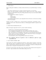
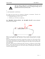
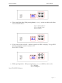
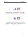
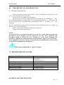
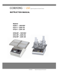
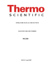
OPERATORS MANUAL FOR USE WITH
MX101 MAXIMIX ORBITAL SHAKER
MD101 MIDIMIX MULTIPURPOSE SHAKER
MN101 MIDIMIX MICROTUBE SHAKER
MN201 MINIMIX MICROPLATE SHAKER
ISSUE 2 MARCH 2004
DIGITAL SHAKERS
TABLE OF CONTENTS
1.0. GENERAL DESCRIPTION
1.1. DEFINITION
1.2. PRINCIPE OF OPERATION
2.0. TECHNICAL FEATURES
2.1. CONSTRUCTION
2.2. GENERAL FEATURES OF SHAKER
3.0. INSTALLATION OF SHAKER
3.1. UNPACKING
3.2. SELECTING THE RIGHT PLACE
3.3. ATTACHING POWER CORD
3.4. ENVIRONMENT CONDITIONS
USER’S MANUAL
Page
3
3
3
3
3
3
5
5
5
5
6
4.0. PROPER INSTALATION OF SHAKER PLATE (Vibromix 30)
6
5.0. INSTRUCTIONS FOR USE
7
5.1. INTRODUCTION
5.2. BASIC OPERATION
5.3. ADDITIONAL OPERATIONS
6.0. DESCRIPTION OF ABNORMAL USE
6.1. GENERAL DESCRIPTION
7
7
10
11
11
7.0. TROUBLESHOOTING GUIDE
11
8.0. REGULAR MAINTANCE
12
8.1. CLEANING
12
9.0. WARRENTY
12
1.0. GENERAL DESCRIPTION
Page
2
DIGITAL SHAKERS
USER’S MANUAL
1.1. DEFINITION
This range of shakers is intended for shaking microtiter plates, tubes, bottles, dishes and other
laboratory vessels. Shaker is driven by the asynchronous motor, which enable silent
operation, constant shaking speed independent of the load or power supply oscillations.
1.2. PRINCIPE OF OPERATION
Device consists of two main parts:
- Motor with eccentricity mechanism
- Control electronics
Motor movement causes orbital movement of shaker’s eccentricity mechanics and generates
shaking effect.
Control electronics supervises motor RPM, TIME and keyboard functions.
2.0. TECHNICAL FEATURES
2.1. CONSTRUCTION
The casing of shaker is made of steel plate varnished with high resistant polyurethane lacquer.
2.2. GENERAL FEATURES OF SHAKERS
MN201MIDIMIX MICROPLATE SHAKER
ELECTRIC POWER SUPPLY
MOTOR POWER
FUSE
RPM REGULATION
SHAKER ORBIT
TIMER
LOAD
DIMENSIONS W x L x H
WEIGHT
230V ± 10% - 50Hz, 115V ± 10% - 60Hz
15W
2 x 0.25A 230V
2 x 1 A 115V
DIGITAL, load independent, from 100 to 1200
(1400 - 115V version) RPM in 10 RPM steps
3 mm
30 sec - 99min 50sec. in 10 sec. steps, under 10 min.
in 1 sec. steps, timer HOLD function
Max. 2 kg
170mm x 275mm x 130mm
4,3 kg
MN101, MN201 MINMIX MULTIPURPOSE SHAKER
Page
3
DIGITAL SHAKERS
ELECTRIC POWER SUPPLY
MOTOR POWER
FUSE
RPM REGULATION
SHAKER ORBIT
TIMER
LOAD
DIMENSIONS W x L x H
WEIGHT
USER’S MANUAL
230V ± 10% - 50Hz, 115V ± 10% - 60Hz
15W
2 x 0.25A 230V
2 x 1 A 115V
DIGITAL, load independent, from 100 to 1200 RPM
in 10 RPM steps
3 mm
30 sec - 99min 50sec. in 10 sec. steps, under 10 min.
in 1 sec. steps, timer HOLD function
Max. 2 kg
255mm x 312mm x 130mm
5,6 kg
MD101 MIDIMIX MULTIPURPOSE SHAKER
ELECTRIC POWER SUPPLY
MOTOR POWER
FUSE
RPM REGULATION
SHAKER ORBIT
TIMER
LOAD
DIMENSIONS W x L x H
WEIGHT
230V ± 10% - 50Hz, 115V ± 10% - 60Hz
15W
2 x 0.25A 230V
2 x 1 A 115V
DIGITAL, load independent, from 50 to 600 RPM in
10 RPM steps
3 mm – 611 code shaker
5 mm – 612 code shaker
10 mm – 613 code shaker
38 mm – 614 code shaker
30 sec - 99min 50sec. in 10 sec. steps, under 10 min.
in 1 sec. steps, timer HOLD function
Max. 2 kg
255mm x 312mm x 130mm
7,1 kg
MX101 MAXIMIX ORBITAL SHAKER
ELECTRIC POWER SUPPLY
MOTOR POWER
FUSE
RPM REGULATION
SHAKER ORBIT
TIMER
LOAD
DIMENSIONS W x L x H
WEIGHT
230V ± 10% - 50Hz, 115V ± 10% - 60Hz
50W
2 x 1 A 230V
2 x 2 A 115V
DIGITAL, load independent, from 20 to 300 RPM in
1 RPM step
20 mm
30 sec - 99min 50sec. in 10 sec. steps, under 10 min.
in 1 sec. steps, timer HOLD function
Max. 10 kg
390mm x 465mm x 160mm
21 kg
3.0. INSTALLATION OF THE SHAKER
Page
4
DIGITAL SHAKERS
USER’S MANUAL
3.1. UNPACKING
Before starting the installation, carefully examine the delivery for possible damage or missing
parts.
- Open the box and lift the device together with shock absorbers, out of the box.
- Remove the shock absorbers and check that the shaker has not been visibly damaged
during the transportation. Keep the packing material until you are sure that the shaker
works properly.
- Check information on shaker rear plate on:
- Type
- Serial Number
- Article number
- Check that the mains cord has a pin configuration that will fit into a wall socket according
to the local standard.
Should any kind of damage have occurred during transportation, immediately make a
complaint to the carrier. Any incorrect delivery or missing parts should be reported to the
distributor.
3.2. SELECTING THE RIGHT PLACE
When selecting the right place for device, please consider following:
-
Put the device on smooth, horizontal and stable place.
Leave enough space beyond the device for normal air circulation, min. 10 cm.
Leave enough space around the device, that you will easy control and maintain it.
Don’t use the device in surroundings, where there are fast temperature and humidity
changes. Please avoid also such places, which are under direct access of sun light or
places nearby devices which producing heat.
Avoid such places, where exist possibility of shocks and vibrations.
Note: The equipment shall not be placed so, that it is difficult to pull out a plug
from mains cord.
3.3. ATTACHING POWER CORD
Fit the mains cord, which is included in the delivery, into the mains receptacle. Connect the
other end of the cord to a grounded wall socket. To avoid interference from noise, surges and
spikes, a dedicated line is preferred. If no such line is available, avoid lines to which powerful
electric motors, refrigerators and similar devices are connected.
The power can be turned on and off by means of the main switch located on the front panel of
the device. Light, mounted in the switch indicates that power is on.
Page
5
DIGITAL SHAKERS
USER’S MANUAL
Take care when you plug cord to a grounded wall socket. Do not touch
plug with wet hand, because it can be very dangerous. Plug cord to a
grounded wall socket only with dry hand.
•
3.4. ENVIRONMENT CONDITIONS
The shaker has been built for operating in laboratory environments. Therefore the
environmental parameters as reference are the following:
• Temperature between -10°C to +70°C
• Humidity up to 85% RH, non-condensing
4.0. PROPER INSTALATION OF SHAKER PLATE (MN201MIDIMIX
MICROPLATE SHAKER)
Before you fix appropriate shaking plate you have to fasten slide accessories on proper
position and lubricate the slide accessories a little with the enclosed grease (see upper
picture).
Each of the shaking plates has the rubber coating surface with the circle cutout and the fixing
screws in the center. Remove circle cutout rubber, screw down four screws on shaker. After
fix the shaking plate, remove non-adhesive backing paper of the rubber circle cutout and paste
it on to same place.
The grease, which you use to lubricate the slide accessories, is sufficient for 1000 working
hours (1 year). After that time you should remove the shaking plate and clean the slide
accessories. If the slide accessories are worn out too much, you should replace them and then
set them to appropriate height.
Page
6
DIGITAL SHAKERS
USER’S MANUAL
5.0. INSTRUCTIONS FOR USE
5.1. INTRODUCTION
RUN
POWER
TIME
nx10 (RPM)
RPM
t (min)
1.
2.
3.
4.
5.
6.
POWER key – switch ON (power key shine) or OFF shaker
RUN green signal light – shine when shaker running
TIME yellow signal light – shine when shaker is set on time
RPM yellow signal light – shine when shaker is set on rpm
+ Button – set up values for TIME or RPM
– Button – set down values for TIME or RPM
If you hold (+) or (-) button for long time values go up or down on display quickly.
7. SELECT button – select between TIME and RPM mode
8. START/STOP button – START or STOP shaking
5.2. BASIC OPERATION
RUN
POWER
•
TIME
nx10 (RPM)
RPM
t (min)
Press POWER key on control panel. On display shaker automatically detect supply
frequency F50 or F60. Likewise shaker is then set on time.
Page
7
DIGITAL SHAKERS
USER’S MANUAL
RUN
POWER
•
nx10 (RPM)
RPM
t (min)
Time signal light shine. With pressing button (+) or (-) set time on desire value from
30 sec to 99 min 50 sec:
99.5 ⇒ 99 min 50 sec
9.59 ⇒ 9 min 59 sec
0.30 ⇒ 30 sec
RUN
POWER
•
TIME
TIME
nx10 (RPM)
RPM
t (min)
If you want set time on hold - continue operation set HLd on display. You get HLd
function on display under 0.30 or above 99.5
Press SELECT button.
RUN
POWER
TIME
nx10 (RPM)
RPM
t (min)
•
RPM signal light shine. . With pressing button (+) or (-) set RPM on desire value:
34 ⇒ 340 Rpm
120 ⇒ 1200 Rpm
Press START/STOP button.
Page
8
DIGITAL SHAKERS
USER’S MANUAL
RUN
POWER
•
TIME
nx10 (RPM)
RPM
t (min)
RUN and TIME signal light shine. Shaker count down time from set value.
NOTE: YOU CAN NOT MODIFY TIME DURING SHAKING
RUN
POWER
•
nx10 (RPM)
RPM
t (min)
If you want change RPM during shaking press SELECT button if shaker is not set on
RPM (RPM signal light shine). With pressing button (+) or (-) select RPM on desire
value. In the meantime RPM signal light pulse. When you stop pressing button (+) or
button (-) signal light RPM stop pulse after 2 sec.
RUN
POWER
•
TIME
TIME
nx10 (RPM)
RPM
t (min)
When time elapse or you press again START/STOP button on display is shown
inscription End and signal light RUN pulse. When shaker completely stop shaking it
place itself on last used values for TIME and RPM.
Page
9
DIGITAL SHAKERS
USER’S MANUAL
5.3. ADDITIONAL OPERATIONS
RUN
POWER
•
TIME
nx10 (RPM)
RPM
t (min)
If you want to look set value for RPM during shaking press button (+) or button (-)
only for ONE CLICK. On display pulse RPM signal light for 2 sec and display show
set RPM. After 2 sec is on display again shown real RPM and signal light stop pulse.
NOTE: Shaker must be on RPM mode – RPM signal light must shine.
RUN
POWER
•
TIME
nx10 (RPM)
RPM
t (min)
If you want to look set value for TIME during shaking press button (+) or button (-)
only for ONE CLICK. On display pulse TIME signal light for 2 sec and display show
set TIME. After 2 sec is on display again shown real TIME and signal light stop pulse.
NOTE: Shaker must be on TIME mode – TIME signal light must shine.
Page
10
DIGITAL SHAKERS
6.0.
USER’S MANUAL
DESCRIPTION OF ABNORMAL USE
6.1. GENERAL DESCRIPTION
Do not use the device nearby water sources. Take care, that water will not drop in the
device, especially by cleaning procedures.
Do not use device in aggressive atmosphere.
Do not put any electricity conducting objects into the device. It could happen
that
you could touch dangerous voltage points. To avoid such shock hazards or destroying the
device it is better in case of malfunction to call authorized service
provided
by
your
distributor.
In case of malfunction unplug the device from mains and call authorized service. You have to
call the service in following cases:
Mains cord or mains receptacle are harmed or destroyed.
Liquid was drooped into the device.
NOTE:
In case that device is not function properly even you have exactly followed instructions
described in User’s Manual, you are allowed to use only those commands and
procedures, which are allowed by User’s Manual. Use of any other commands and
procedure’s adjustments could result in device destruction or longer service repair time.
If the equipment is used in a manner not specified by the manufacturer, the protection
provide by the equipment may be impaired.
Do not shake inflammable or explosive samples!
7.0. TROUBLESHOOTING GUIDE
Problem
POWER key doesn’t shine
Display doesn’t shine
Message ER1 on display
Message ER2 on display
Message ER3 on display
Message ER4 on display
Explanation / Solution
Check the power supply
Check fuses
Call nearest service
Call nearest service
Call nearest service
Call nearest service
Call nearest service
Call nearest service
8.0. REGULAR MAINTIANANCE
Page
11
DIGITAL SHAKERS
•
•
•
USER’S MANUAL
No extra regular maintianance is needed.
The maintianance people should regularly check the device operation at least once a
year.
Regular cleaning recommended.
8.1. CLEANING
Housing of Shaker Unit can be cleaned with special cleaners for plastic surfaces (car interiorarmature).
NOTE:
Do not use any aggressive or abrasive cleaners (aceton, nitro, polish etc.) because its
surface can be permanently damaged.
Before cleaning device, unplug main cord from wall socket.
9.0 Warranty
The manufacturer warrants this product against defects in material and workmanship
for a period of one year from receipt by the end user. During the warranty period the
manufacturer will, at their discretion, either repair or replace the product/s, which
prove to be defective.
Should this instrument require service attention or if replacement parts are required,
please contact:
UK
The Service Department
Thermo Scientific
Unit 5,
The Ringway Centre
Edison Road
Basingstoke
Hampshire
RG21 6YH
Tel: 0870 609 9203
Fax: 0870 609 9202
Other Countries
Please contact the local authorised Thermo Scientific Distributor or Service Agent.
Page
12