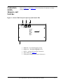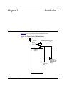
1
®
Accu-Time Series 7000
Access Control Unit
User’s Manual
MANU7000-01h
ACCU-TIME SYSTEMS, INC.
420 SOMERS ROAD
ELLINGTON, CONNECTICUT
Copyright © 2003, 2004 by Accu-Time Systems, Inc. All rights reserved. Printed in U.S.A.
Information in this document is subject to change without notice and should not be construed as a commitment by
Accu-Time Systems, Inc. No part of this document may be reproduced or transmitted in any form or by any means,
electronic or mechanical, without express written consent of Accu-Time Systems, Inc.
Accu-Time, Accu-Rate, and the Accu-Time logo are registered trademarks of Accu-Time Systems, Inc.
All other trademarks and registered trademarks are the property of their respective owners.
Accu-Time Systems, Inc.
420 Somers Road
Ellington, Connecticut 06029 USA
(860) 870-5000
(800) 355-4648
www.accu-time.com
Printed August 24, 2004 MANU7000-01h
FCC Statement
This equipment has been tested and found to comply with the limits for a Class A
digital device pursuant to Part 15 of the FCC rules. These limits are designed to
provide reasonable protection against harmful interference in a residential
installation. This equipment generates, uses, and can radiate radio frequency energy
and, if not installed and used in accordance with the instructions, may cause harmful
interference to radio communications. However, there is no guarantee that
interference will not occur in a particular installation. If this equipment does cause
harmful interference to radio or television reception, which can be determined by
turning the equipment off and on, the user is encouraged to try to correct the
interference by one or more of the following measures:
•
Reorient or relocate the receiving antenna.
•
Increase the distance between the time clock and the receiver.
•
Connect the equipment into an outlet on a circuit different from that which the
receiver is connected.
FCC Warning: To assure continued FCC emission limit compliance, the user must
use only the recommended shielded interfacing cable when connecting to a host
computer. Also, any unauthorized changes or modifications to this equipment
would void the user authority to operate this device.
Table of Contents
Preface
Purpose . . . . . . . . . . . . . . . . . . . . . . . . . . . . . . . . . . . . . . . . . . . . . . . . . . . . . . . . . . . . . . . . . . . . . . . . . x
Intended Audience . . . . . . . . . . . . . . . . . . . . . . . . . . . . . . . . . . . . . . . . . . . . . . . . . . . . . . . . . . . . . . . . x
Structure . . . . . . . . . . . . . . . . . . . . . . . . . . . . . . . . . . . . . . . . . . . . . . . . . . . . . . . . . . . . . . . . . . . . . . . . x
Document Conventions . . . . . . . . . . . . . . . . . . . . . . . . . . . . . . . . . . . . . . . . . . . . . . . . . . . . . . . . . . . . xi
Character Representations . . . . . . . . . . . . . . . . . . . . . . . . . . . . . . . . . . . . . . . . . . . . . . . . . . . . . . xii
Using The Manual Electronically . . . . . . . . . . . . . . . . . . . . . . . . . . . . . . . . . . . . . . . . . . . . . . . . . xii
Feedback . . . . . . . . . . . . . . . . . . . . . . . . . . . . . . . . . . . . . . . . . . . . . . . . . . . . . . . . . . . . . . . . . . . . . . xiii
1
Introduction
Technical Summary . . . . . . . . . . . . . . . . . . . . . . . . . . . . . . . . . . . . . . . . . . . . . . . . . . . . . . . . . . . . . .
Switches/Jumpers . . . . . . . . . . . . . . . . . . . . . . . . . . . . . . . . . . . . . . . . . . . . . . . . . . . . . . . . . . . .
Firmware . . . . . . . . . . . . . . . . . . . . . . . . . . . . . . . . . . . . . . . . . . . . . . . . . . . . . . . . . . . . . . . . . . .
Power Fail . . . . . . . . . . . . . . . . . . . . . . . . . . . . . . . . . . . . . . . . . . . . . . . . . . . . . . . . . . . . . . . . . .
1-2
1-3
1-4
1-4
Connectors, LEDS, Jumpers, and Switches . . . . . . . . . . . . . . . . . . . . . . . . . . . . . . . . . . . . . . . . . . . .
Operating Modes . . . . . . . . . . . . . . . . . . . . . . . . . . . . . . . . . . . . . . . . . . . . . . . . . . . . . . . . . . . . . . . .
Test Mode . . . . . . . . . . . . . . . . . . . . . . . . . . . . . . . . . . . . . . . . . . . . . . . . . . . . . . . . . . . . . . . . . .
Standalone Mode . . . . . . . . . . . . . . . . . . . . . . . . . . . . . . . . . . . . . . . . . . . . . . . . . . . . . . . . . . . .
Online Mode . . . . . . . . . . . . . . . . . . . . . . . . . . . . . . . . . . . . . . . . . . . . . . . . . . . . . . . . . . . . . . . .
On Line Mode, Dual Door . . . . . . . . . . . . . . . . . . . . . . . . . . . . . . . . . . . . . . . . . . . . . . . . . . . . .
Reset . . . . . . . . . . . . . . . . . . . . . . . . . . . . . . . . . . . . . . . . . . . . . . . . . . . . . . . . . . . . . . . . . . . . . . . . .
1-5
1-7
1-7
1-8
1-8
1-8
1-8
Validation Table . . . . . . . . . . . . . . . . . . . . . . . . . . . . . . . . . . . . . . . . . . . . . . . . . . . . . . . . . . . . . . . .
Validation Table Online Download . . . . . . . . . . . . . . . . . . . . . . . . . . . . . . . . . . . . . . . . . . . . .
Standalone Validation Table . . . . . . . . . . . . . . . . . . . . . . . . . . . . . . . . . . . . . . . . . . . . . . . . . .
Single Card Add/Disable/Enable . . . . . . . . . . . . . . . . . . . . . . . . . . . . . . . . . . . . . . . . . . . .
1-10
1-10
1-10
1-10
Schedules . . . . . . . . . . . . . . . . . . . . . . . . . . . . . . . . . . . . . . . . . . . . . . . . . . . . . . . . . . . . . . . . . . . . . 1-11
Accu-Time® Series 7000 Access Control Unit User’s Guide
iv
Door lock/release operation (DO_1) . . . . . . . . . . . . . . . . . . . . . . . . . . . . . . . . . . . . . . . . . . . . . . . .
“Good Swipe” and “Badge Valid” . . . . . . . . . . . . . . . . . . . . . . . . . . . . . . . . . . . . . . . . . . . . . .
”Good Swipe” and “Badge Not Valid” . . . . . . . . . . . . . . . . . . . . . . . . . . . . . . . . . . . . . . . . . .
”Bad Swipe” . . . . . . . . . . . . . . . . . . . . . . . . . . . . . . . . . . . . . . . . . . . . . . . . . . . . . . . . . . . . . .
Badge Swipe and Alarm Logging . . . . . . . . . . . . . . . . . . . . . . . . . . . . . . . . . . . . . . . . . . . . . .
Anti-Passback . . . . . . . . . . . . . . . . . . . . . . . . . . . . . . . . . . . . . . . . . . . . . . . . . . . . . . . . . . . . . . . . .
1-11
1-11
1-11
1-11
1-12
1-12
Standalone Mode . . . . . . . . . . . . . . . . . . . . . . . . . . . . . . . . . . . . . . . . . . . . . . . . . . . . . . . . . . . . . . . 1-13
Using the Master badge . . . . . . . . . . . . . . . . . . . . . . . . . . . . . . . . . . . . . . . . . . . . . . . . . . . . . . 1-13
Host Communications . . . . . . . . . . . . . . . . . . . . . . . . . . . . . . . . . . . . . . . . . . . . . . . . . . . . . . . . . . .
AccuComm/ Test Program . . . . . . . . . . . . . . . . . . . . . . . . . . . . . . . . . . . . . . . . . . . . . . . . . . .
Dynamic Link Library Files . . . . . . . . . . . . . . . . . . . . . . . . . . . . . . . . . . . . . . . . . . . . . . . . . . .
Employee Identification . . . . . . . . . . . . . . . . . . . . . . . . . . . . . . . . . . . . . . . . . . . . . . . . . . . . . .
2
1-14
1-14
1-14
1-14
Installation
Installation Guidelines . . . . . . . . . . . . . . . . . . . . . . . . . . . . . . . . . . . . . . . . . . . . . . . . . . . . . . . . . . .
Environmental Considerations . . . . . . . . . . . . . . . . . . . . . . . . . . . . . . . . . . . . . . . . . . . . . . . . . .
Mounting . . . . . . . . . . . . . . . . . . . . . . . . . . . . . . . . . . . . . . . . . . . . . . . . . . . . . . . . . . . . . . . . . .
Power . . . . . . . . . . . . . . . . . . . . . . . . . . . . . . . . . . . . . . . . . . . . . . . . . . . . . . . . . . . . . . . . . . . . .
Cabling . . . . . . . . . . . . . . . . . . . . . . . . . . . . . . . . . . . . . . . . . . . . . . . . . . . . . . . . . . . . . . . . . . . .
Cabling Accessories . . . . . . . . . . . . . . . . . . . . . . . . . . . . . . . . . . . . . . . . . . . . . . . . . . . . . . .
RS232 . . . . . . . . . . . . . . . . . . . . . . . . . . . . . . . . . . . . . . . . . . . . . . . . . . . . . . . . . . . . . . . . . .
RS485 . . . . . . . . . . . . . . . . . . . . . . . . . . . . . . . . . . . . . . . . . . . . . . . . . . . . . . . . . . . . . . . . . .
2-2
2-2
2-2
2-3
2-3
2-4
2-5
2-5
Connecting the Reader and DI/DO Wiring . . . . . . . . . . . . . . . . . . . . . . . . . . . . . . . . . . . . . . . . . . . . 2-6
Wiring the Readers . . . . . . . . . . . . . . . . . . . . . . . . . . . . . . . . . . . . . . . . . . . . . . . . . . . . . . . . . . . 2-7
Wiring the Digital Inputs (DI_1 and DI_2) . . . . . . . . . . . . . . . . . . . . . . . . . . . . . . . . . . . . . . . . 2-8
Wiring the Digital Outputs (DO_1 and DO_2) . . . . . . . . . . . . . . . . . . . . . . . . . . . . . . . . . . . . . 2-9
Wiring the Door Lock . . . . . . . . . . . . . . . . . . . . . . . . . . . . . . . . . . . . . . . . . . . . . . . . . . . . . 2-9
Wiring an Alarm . . . . . . . . . . . . . . . . . . . . . . . . . . . . . . . . . . . . . . . . . . . . . . . . . . . . . . . . 2-10
Operation . . . . . . . . . . . . . . . . . . . . . . . . . . . . . . . . . . . . . . . . . . . . . . . . . . . . . . . . . . . . . . . . . 2-10
Wiring the Tamper Switch . . . . . . . . . . . . . . . . . . . . . . . . . . . . . . . . . . . . . . . . . . . . . . . . . . . . 2-10
Setting the DIP Switches . . . . . . . . . . . . . . . . . . . . . . . . . . . . . . . . . . . . . . . . . . . . . . . . . . . . . . . . .
DIP Switch 1 . . . . . . . . . . . . . . . . . . . . . . . . . . . . . . . . . . . . . . . . . . . . . . . . . . . . . . . . . . . . . . .
1. Test Switch Disable . . . . . . . . . . . . . . . . . . . . . . . . . . . . . . . . . . . . . . . . . . . . . . . . . . . .
2. Tamper Switch Disable . . . . . . . . . . . . . . . . . . . . . . . . . . . . . . . . . . . . . . . . . . . . . . . . .
3. Default Reset . . . . . . . . . . . . . . . . . . . . . . . . . . . . . . . . . . . . . . . . . . . . . . . . . . . . . . . . .
4. RS232/RS485 Mode . . . . . . . . . . . . . . . . . . . . . . . . . . . . . . . . . . . . . . . . . . . . . . . . . . .
5. Reserved . . . . . . . . . . . . . . . . . . . . . . . . . . . . . . . . . . . . . . . . . . . . . . . . . . . . . . . . . . . . .
6. Single/Dual Door Mode . . . . . . . . . . . . . . . . . . . . . . . . . . . . . . . . . . . . . . . . . . . . . . . . .
7. ATS Serial Protocol . . . . . . . . . . . . . . . . . . . . . . . . . . . . . . . . . . . . . . . . . . . . . . . . . . . .
8. Online/Standalone . . . . . . . . . . . . . . . . . . . . . . . . . . . . . . . . . . . . . . . . . . . . . . . . . . . . .
DIP Switch 2 . . . . . . . . . . . . . . . . . . . . . . . . . . . . . . . . . . . . . . . . . . . . . . . . . . . . . . . . . . . . . . .
1-2. Reader 0 Type . . . . . . . . . . . . . . . . . . . . . . . . . . . . . . . . . . . . . . . . . . . . . . . . . . . . . . .
3. Reader 1 Type . . . . . . . . . . . . . . . . . . . . . . . . . . . . . . . . . . . . . . . . . . . . . . . . . . . . . . . .
Accu-Time® Series 7000 Access Control Unit User’s Guide
2-11
2-11
2-11
2-11
2-11
2-11
2-11
2-11
2-11
2-11
2-12
2-12
2-12
v
4-8. Unit Address . . . . . . . . . . . . . . . . . . . . . . . . . . . . . . . . . . . . . . . . . . . . . . . . . . . . . . . . 2-12
Setting the Jumpers . . . . . . . . . . . . . . . . . . . . . . . . . . . . . . . . . . . . . . . . . . . . . . . . . . . . . . . . . . . . . 2-13
3
Commands
Command Syntax . . . . . . . . . . . . . . . . . . . . . . . . . . . . . . . . . . . . . . . . . . . . . . . . . . . . . . . . . . . . . . . 3-2
Command Index . . . . . . . . . . . . . . . . . . . . . . . . . . . . . . . . . . . . . . . . . . . . . . . . . . . . . . . . . . . . . . . . . 3-3
General Commands . . . . . . . . . . . . . . . . . . . . . . . . . . . . . . . . . . . . . . . . . . . . . . . . . . . . . . . . . . . . . . 3-5
AQ10 . . . . . . . . . . . . . . . . . . . . . . . . . . . . . . . . . . . . . . . . . . . . . . . . . . . . . . . . . . . . . . . 3-5
C00 . . . . . . . . . . . . . . . . . . . . . . . . . . . . . . . . . . . . . . . . . . . . . . . . . . . . . . . . . . . . . . . . 3-5
D10 . . . . . . . . . . . . . . . . . . . . . . . . . . . . . . . . . . . . . . . . . . . . . . . . . . . . . . . . . . . . . . . . 3-6
D20 . . . . . . . . . . . . . . . . . . . . . . . . . . . . . . . . . . . . . . . . . . . . . . . . . . . . . . . . . . . . . . . . 3-6
LAP01 . . . . . . . . . . . . . . . . . . . . . . . . . . . . . . . . . . . . . . . . . . . . . . . . . . . . . . . . . . . . . . 3-7
LDA01 . . . . . . . . . . . . . . . . . . . . . . . . . . . . . . . . . . . . . . . . . . . . . . . . . . . . . . . . . . . . . . 3-7
LPB01 . . . . . . . . . . . . . . . . . . . . . . . . . . . . . . . . . . . . . . . . . . . . . . . . . . . . . . . . . . . . . . 3-7
LPB03 . . . . . . . . . . . . . . . . . . . . . . . . . . . . . . . . . . . . . . . . . . . . . . . . . . . . . . . . . . . . . . 3-8
LPB04 . . . . . . . . . . . . . . . . . . . . . . . . . . . . . . . . . . . . . . . . . . . . . . . . . . . . . . . . . . . . . . 3-8
LPB05 . . . . . . . . . . . . . . . . . . . . . . . . . . . . . . . . . . . . . . . . . . . . . . . . . . . . . . . . . . . . . . 3-9
LSA01 . . . . . . . . . . . . . . . . . . . . . . . . . . . . . . . . . . . . . . . . . . . . . . . . . . . . . . . . . . . . . . 3-9
O00 . . . . . . . . . . . . . . . . . . . . . . . . . . . . . . . . . . . . . . . . . . . . . . . . . . . . . . . . . . . . . . . 3-10
O10 . . . . . . . . . . . . . . . . . . . . . . . . . . . . . . . . . . . . . . . . . . . . . . . . . . . . . . . . . . . . . . . 3-10
R00 . . . . . . . . . . . . . . . . . . . . . . . . . . . . . . . . . . . . . . . . . . . . . . . . . . . . . . . . . . . . . . . 3-11
R01 . . . . . . . . . . . . . . . . . . . . . . . . . . . . . . . . . . . . . . . . . . . . . . . . . . . . . . . . . . . . . . . . 3-11
S00 . . . . . . . . . . . . . . . . . . . . . . . . . . . . . . . . . . . . . . . . . . . . . . . . . . . . . . . . . . . . . . . . 3-11
S01 . . . . . . . . . . . . . . . . . . . . . . . . . . . . . . . . . . . . . . . . . . . . . . . . . . . . . . . . . . . . . . . . 3-12
S02 . . . . . . . . . . . . . . . . . . . . . . . . . . . . . . . . . . . . . . . . . . . . . . . . . . . . . . . . . . . . . . . . 3-12
S03 . . . . . . . . . . . . . . . . . . . . . . . . . . . . . . . . . . . . . . . . . . . . . . . . . . . . . . . . . . . . . . . 3-13
S04 . . . . . . . . . . . . . . . . . . . . . . . . . . . . . . . . . . . . . . . . . . . . . . . . . . . . . . . . . . . . . . . . 3-13
T00 . . . . . . . . . . . . . . . . . . . . . . . . . . . . . . . . . . . . . . . . . . . . . . . . . . . . . . . . . . . . . . . . 3-14
T10 . . . . . . . . . . . . . . . . . . . . . . . . . . . . . . . . . . . . . . . . . . . . . . . . . . . . . . . . . . . . . . . . 3-14
T20 . . . . . . . . . . . . . . . . . . . . . . . . . . . . . . . . . . . . . . . . . . . . . . . . . . . . . . . . . . . . . . . . 3-14
Employee File Handling Commands . . . . . . . . . . . . . . . . . . . . . . . . . . . . . . . . . . . . . . . . . . . . . . . .
LEE01 . . . . . . . . . . . . . . . . . . . . . . . . . . . . . . . . . . . . . . . . . . . . . . . . . . . . . . . . . . . . .
LEC01 . . . . . . . . . . . . . . . . . . . . . . . . . . . . . . . . . . . . . . . . . . . . . . . . . . . . . . . . . . . . .
LED01 . . . . . . . . . . . . . . . . . . . . . . . . . . . . . . . . . . . . . . . . . . . . . . . . . . . . . . . . . . . . .
3-16
3-16
3-16
3-17
Badge Masking and Validation Commands . . . . . . . . . . . . . . . . . . . . . . . . . . . . . . . . . . . . . . . . . . . 3-18
LEB01 . . . . . . . . . . . . . . . . . . . . . . . . . . . . . . . . . . . . . . . . . . . . . . . . . . . . . . . . . . . . . 3-18
Schedule File Handling . . . . . . . . . . . . . . . . . . . . . . . . . . . . . . . . . . . . . . . . . . . . . . . . . . . . . . . . . .
LSE01 . . . . . . . . . . . . . . . . . . . . . . . . . . . . . . . . . . . . . . . . . . . . . . . . . . . . . . . . . . . . .
LSB01 . . . . . . . . . . . . . . . . . . . . . . . . . . . . . . . . . . . . . . . . . . . . . . . . . . . . . . . . . . . . .
LSC01 . . . . . . . . . . . . . . . . . . . . . . . . . . . . . . . . . . . . . . . . . . . . . . . . . . . . . . . . . . . . .
LSD01 . . . . . . . . . . . . . . . . . . . . . . . . . . . . . . . . . . . . . . . . . . . . . . . . . . . . . . . . . . . . .
LHO101 . . . . . . . . . . . . . . . . . . . . . . . . . . . . . . . . . . . . . . . . . . . . . . . . . . . . . . . . . . . .
Accu-Time® Series 7000 Access Control Unit User’s Guide
3-20
3-20
3-20
3-21
3-22
3-22
vi
Bell Schedule File Handling . . . . . . . . . . . . . . . . . . . . . . . . . . . . . . . . . . . . . . . . . . . . . . . . . . . . . . 3-24
LBE01 . . . . . . . . . . . . . . . . . . . . . . . . . . . . . . . . . . . . . . . . . . . . . . . . . . . . . . . . . . . . . 3-24
LBC01 . . . . . . . . . . . . . . . . . . . . . . . . . . . . . . . . . . . . . . . . . . . . . . . . . . . . . . . . . . . . . 3-24
Interactive Commands . . . . . . . . . . . . . . . . . . . . . . . . . . . . . . . . . . . . . . . . . . . . . . . . . . . . . . . . . . .
BELL . . . . . . . . . . . . . . . . . . . . . . . . . . . . . . . . . . . . . . . . . . . . . . . . . . . . . . . . . . . . . .
SO . . . . . . . . . . . . . . . . . . . . . . . . . . . . . . . . . . . . . . . . . . . . . . . . . . . . . . . . . . . . . . . .
SI . . . . . . . . . . . . . . . . . . . . . . . . . . . . . . . . . . . . . . . . . . . . . . . . . . . . . . . . . . . . . . . . .
3-26
3-26
3-26
3-26
Controlling Relays DO_1, DO_2. . . . . . . . . . . . . . . . . . . . . . . . . . . . . . . . . . . . . . . . . . . . . . . . . . .
DC101 . . . . . . . . . . . . . . . . . . . . . . . . . . . . . . . . . . . . . . . . . . . . . . . . . . . . . . . . . . . . .
DC100 . . . . . . . . . . . . . . . . . . . . . . . . . . . . . . . . . . . . . . . . . . . . . . . . . . . . . . . . . . . . .
DC111 . . . . . . . . . . . . . . . . . . . . . . . . . . . . . . . . . . . . . . . . . . . . . . . . . . . . . . . . . . . . .
DC201 . . . . . . . . . . . . . . . . . . . . . . . . . . . . . . . . . . . . . . . . . . . . . . . . . . . . . . . . . . . . .
DC200 . . . . . . . . . . . . . . . . . . . . . . . . . . . . . . . . . . . . . . . . . . . . . . . . . . . . . . . . . . . . .
DC211 . . . . . . . . . . . . . . . . . . . . . . . . . . . . . . . . . . . . . . . . . . . . . . . . . . . . . . . . . . . . .
3-28
3-28
3-28
3-28
3-29
3-29
3-29
Messages Received From ACU . . . . . . . . . . . . . . . . . . . . . . . . . . . . . . . . . . . . . . . . . . . . . . . . . . . .
ALDI1 . . . . . . . . . . . . . . . . . . . . . . . . . . . . . . . . . . . . . . . . . . . . . . . . . . . . . . . . . . . . .
ALDI2 . . . . . . . . . . . . . . . . . . . . . . . . . . . . . . . . . . . . . . . . . . . . . . . . . . . . . . . . . . . . .
ALSTATE . . . . . . . . . . . . . . . . . . . . . . . . . . . . . . . . . . . . . . . . . . . . . . . . . . . . . . . . . .
ALTAMP . . . . . . . . . . . . . . . . . . . . . . . . . . . . . . . . . . . . . . . . . . . . . . . . . . . . . . . . . . .
BA01 . . . . . . . . . . . . . . . . . . . . . . . . . . . . . . . . . . . . . . . . . . . . . . . . . . . . . . . . . . . . . .
BA02 . . . . . . . . . . . . . . . . . . . . . . . . . . . . . . . . . . . . . . . . . . . . . . . . . . . . . . . . . . . . . .
BG00 . . . . . . . . . . . . . . . . . . . . . . . . . . . . . . . . . . . . . . . . . . . . . . . . . . . . . . . . . . . . . .
BG01 . . . . . . . . . . . . . . . . . . . . . . . . . . . . . . . . . . . . . . . . . . . . . . . . . . . . . . . . . . . . . .
BS00 . . . . . . . . . . . . . . . . . . . . . . . . . . . . . . . . . . . . . . . . . . . . . . . . . . . . . . . . . . . . . .
BS01 . . . . . . . . . . . . . . . . . . . . . . . . . . . . . . . . . . . . . . . . . . . . . . . . . . . . . . . . . . . . . .
BS02 . . . . . . . . . . . . . . . . . . . . . . . . . . . . . . . . . . . . . . . . . . . . . . . . . . . . . . . . . . . . . .
BS03 . . . . . . . . . . . . . . . . . . . . . . . . . . . . . . . . . . . . . . . . . . . . . . . . . . . . . . . . . . . . . .
BS04 . . . . . . . . . . . . . . . . . . . . . . . . . . . . . . . . . . . . . . . . . . . . . . . . . . . . . . . . . . . . . .
BT01 . . . . . . . . . . . . . . . . . . . . . . . . . . . . . . . . . . . . . . . . . . . . . . . . . . . . . . . . . . . . . .
DI00 . . . . . . . . . . . . . . . . . . . . . . . . . . . . . . . . . . . . . . . . . . . . . . . . . . . . . . . . . . . . . . .
P.... . . . . . . . . . . . . . . . . . . . . . . . . . . . . . . . . . . . . . . . . . . . . . . . . . . . . . . . . . . . . . . . .
3-31
3-31
3-31
3-32
3-33
3-33
3-34
3-34
3-35
3-36
3-36
3-37
3-38
3-38
3-39
3-39
3-40
General Command Syntax Notes . . . . . . . . . . . . . . . . . . . . . . . . . . . . . . . . . . . . . . . . . . . . . . . . . . . 3-42
A Minute Offsets
B Pinouts, Interfaces, and Switches
Pinouts . . . . . . . . . . . . . . . . . . . . . . . . . . . . . . . . . . . . . . . . . . . . . . . . . . . . . . . . . . . . . . . . . . . . . . . .
12V Power Input . . . . . . . . . . . . . . . . . . . . . . . . . . . . . . . . . . . . . . . . . . . . . . . . . . . . . . . . . . . . .
RS232 Network . . . . . . . . . . . . . . . . . . . . . . . . . . . . . . . . . . . . . . . . . . . . . . . . . . . . . . . . . . . . .
RS485 Network . . . . . . . . . . . . . . . . . . . . . . . . . . . . . . . . . . . . . . . . . . . . . . . . . . . . . . . . . . . . .
Battery Status Inputs . . . . . . . . . . . . . . . . . . . . . . . . . . . . . . . . . . . . . . . . . . . . . . . . . . . . . . . . . .
B-1
B-1
B-1
B-2
B-2
DIP Switches . . . . . . . . . . . . . . . . . . . . . . . . . . . . . . . . . . . . . . . . . . . . . . . . . . . . . . . . . . . . . . . . . . . B-3
DIP Switch 1 . . . . . . . . . . . . . . . . . . . . . . . . . . . . . . . . . . . . . . . . . . . . . . . . . . . . . . . . . . . . . . . . B-3
Accu-Time® Series 7000 Access Control Unit User’s Guide
vii
DIP Switch 2 . . . . . . . . . . . . . . . . . . . . . . . . . . . . . . . . . . . . . . . . . . . . . . . . . . . . . . . . . . . . . . . . B-3
Standard Reader Connections . . . . . . . . . . . . . . . . . . . . . . . . . . . . . . . . . . . . . . . . . . . . . . . . . . . . . .
Reader 7000/101 and 102 Wiring (Mag Stripe and HiTag Proximity) . . . . . . . . . . . . . . . . . . . .
Keypad 7000/103 . . . . . . . . . . . . . . . . . . . . . . . . . . . . . . . . . . . . . . . . . . . . . . . . . . . . . . . . . . . .
HID “Clock and Data” Reader Wiring . . . . . . . . . . . . . . . . . . . . . . . . . . . . . . . . . . . . . . . . . . . .
Barcode Readers (ATS Weather Resistant 9001/XX) . . . . . . . . . . . . . . . . . . . . . . . . . . . . . . . . . . .
B-4
B-4
B-5
B-6
B-7
C Terminal Addresses
D Sample Download File
Index
Figures
Figure
Figure
Figure
Figure
Figure
Figure
Figure
Figure
Figure
Figure
Figure
Figure
Figure
1-1: Series 7000 Network Connectors and Status LEDs . . . . . . . . . . . . . . . . . . . . . . . . . . . . . . . 1-5
1-2: Series 7000 Switches and Connectors . . . . . . . . . . . . . . . . . . . . . . . . . . . . . . . . . . . . . . . . . 1-6
1-3: Jumpers to Select Types of Readers . . . . . . . . . . . . . . . . . . . . . . . . . . . . . . . . . . . . . . . . . . .1-7
2-1: Typical Series 7000 Installation . . . . . . . . . . . . . . . . . . . . . . . . . . . . . . . . . . . . . . . . . . . . . .2-1
2-2: Typical 12V Power Pack . . . . . . . . . . . . . . . . . . . . . . . . . . . . . . . . . . . . . . . . . . . . . . . . . . .2-3
2-3: Wiring a Terminal Block . . . . . . . . . . . . . . . . . . . . . . . . . . . . . . . . . . . . . . . . . . . . . . . . . . .2-6
2-4: Digital Output (Relay) Connections . . . . . . . . . . . . . . . . . . . . . . . . . . . . . . . . . . . . . . . . . . .2-9
2-5: Alternative Series 7000 Inputs and Outputs Wiring Example . . . . . . . . . . . . . . . . . . . . . . 2-14
2-6: Dual Door Mode Wiring Example . . . . . . . . . . . . . . . . . . . . . . . . . . . . . . . . . . . . . . . . . . . 2-15
2-7: Series 7000 RS232 Serial Installation . . . . . . . . . . . . . . . . . . . . . . . . . . . . . . . . . . . . . . . . 2-16
2-8: Series 7000 RS485 Serial Installation . . . . . . . . . . . . . . . . . . . . . . . . . . . . . . . . . . . . . . . . 2-17
2-9: Series 7000 Mounting Template (Next Page). . . . . . . . . . . . . . . . . . . . . . . . . . . . . . . . . . . 2-17
D-1: Sample Download File. . . . . . . . . . . . . . . . . . . . . . . . . . . . . . . . . . . . . . . . . . . . . . . . . . . . . D-1
Tables
Table 1: Non-Printing Character Representations . . . . . . . . . . . . . . . . . . . . . . . . . . . . . . . . . . . . xii
Table 1-1: Series 7000 Diagnostic LEDs . . . . . . . . . . . . . . . . . . . . . . . . . . . . . . . . . . . . . . . . . . . . . . . . .1-3
Table 2-1: Wire Length Limitations . . . . . . . . . . . . . . . . . . . . . . . . . . . . . . . . . . . . . . . . . . . . . . . . . . . . .2-4
Table 2-2: ACU Reader/Keypad 0 and 1 Connections . . . . . . . . . . . . . . . . . . . . . . . . . . . . . . . . . . . . . . .2-7
Table 2-3: ACU DI Connections . . . . . . . . . . . . . . . . . . . . . . . . . . . . . . . . . . . . . . . . . . . . . . . . . . . . . . . .2-8
Table 2-4: ACU DO Connections . . . . . . . . . . . . . . . . . . . . . . . . . . . . . . . . . . . . . . . . . . . . . . . . . . . . . . .2-9
Table 2-5: Decimal/Binary Unit Number Equivalents . . . . . . . . . . . . . . . . . . . . . . . . . . . . . . . . . . . . . .2-13
Table 3-1: Character Equivalents to Enter Hexadecimal Values . . . . . . . . . . . . . . . . . . . . . . . . . . . . . . .3-2
Table 3-2: Command Index . . . . . . . . . . . . . . . . . . . . . . . . . . . . . . . . . . . . . . . . . . . . . . . . . . . . . . . . . . . .3-3
Table A-1: Schedule Minutes Offset . . . . . . . . . . . . . . . . . . . . . . . . . . . . . . . . . . . . . . . . . . . . . . . . . . . . A-2
Accu-Time® Series 7000 Access Control Unit User’s Guide
viii
Table B-1: RS232 Pinout . . . . . . . . . . . . . . . . . . . . . . . . . . . . . . . . . . . . . . . . . . . . . . . . . . . . . . . . . . . . .
Table B-2: RS485 Pinout . . . . . . . . . . . . . . . . . . . . . . . . . . . . . . . . . . . . . . . . . . . . . . . . . . . . . . . . . . . . .
Table B-3: Battery Status Pinout . . . . . . . . . . . . . . . . . . . . . . . . . . . . . . . . . . . . . . . . . . . . . . . . . . . . . . .
Table B-4: DIP Switch 1 Settings . . . . . . . . . . . . . . . . . . . . . . . . . . . . . . . . . . . . . . . . . . . . . . . . . . . . . .
Table B-5: DIP Switch 2 Settings . . . . . . . . . . . . . . . . . . . . . . . . . . . . . . . . . . . . . . . . . . . . . . . . . . . . . .
Table B-6: Reader 7000/101 and 7000/102 Wiring . . . . . . . . . . . . . . . . . . . . . . . . . . . . . . . . . . . . . . . .
Table B-7: Keypad 7000/103 Wiring (Storm) . . . . . . . . . . . . . . . . . . . . . . . . . . . . . . . . . . . . . . . . . . . . .
Table B-8: HID ProxPoint Plus “Clock and Data” Reader Wiring . . . . . . . . . . . . . . . . . . . . . . . . . . . . .
Table B-9: Barcode Readers 9001/XX Wiring . . . . . . . . . . . . . . . . . . . . . . . . . . . . . . . . . . . . . . . . . . . .
Table C-1: Network Controller ID Addressing Table . . . . . . . . . . . . . . . . . . . . . . . . . . . . . . . . . . . . . . .
Accu-Time® Series 7000 Access Control Unit User’s Guide
B-1
B-2
B-2
B-3
B-3
B-4
B-5
B-6
B-7
C-1
ix
Preface
Purpose
Intended
Audience
Structure
This manual describes the Accu-Time Series 7000 Access Control Unit (ACU)
from Accu-Time Systems, Inc. It tells you how to install, configure, and use the
Series 7000 ACU.
You should read this manual if you plan to use the Accu-Time Series 7000 Access
Control Unit.
This manual has been divided into sections covering installation guidelines,
terminal architecture, configuration commands, host communications, and
troubleshooting. A comprehensive index at the end of the manual provides a means
of locating references to specific topics or commands.
Accu-Time® Series 7000 Access Control Unit User’s Guide
x
The table below explains the conventions used to present information in this
manual.
Convention
Description
Subscripts
Subscripts indicate the base of a number. For example,
2810 is 28 base 10, and 3F16 is 3F base 16.
BOLD CAPITALS
Bold capitals represent keys on a terminal keypad, such as
the ENTER key.
nnnn
nnnn represents a numeric string of digits.
xxxx
xxxx represents a string of alphanumeric characters.
Blue underline
Cross references in the manual are shown as blue
underlined text. If you read this manual online, these
cross-references act as hyperlinks, which work in the same
way as links on a web page. If you click the cursor on a
cross-reference, the display will shift to the corresponding
location in the document. When viewed online, the
document contents are listed in a frame at the left of the
screen that contains hyperlinks to chapters, headings,
figures, and tables. Each entry in the index is also a
hyperlink that will take you to the page on which the
reference is located.
Fixed width
font
Filenames, directory entries, and script or log file text.
italics
A variable or argument for which you supply a value.
Accu-Time® Series 7000 Access Control Unit User’s Guide
xi
Introduction
Document
Conventions
Character
Representations
The syntax of commands includes some non-printing control characters (character
codes 000 to 03110, 000 to 1F16) plus the space character. These non-printing
characters and the space character are represented in this manual in various ways as
shown in the table below. In many text editors, you can generate a control character
by holding down the CTRL key and pressing the appropriate printing key. For
example, you can generate a record separator (3010, 1E16) by holding down the
CTRL key and pressing the caret ^ key (SHIFT 6).This key sequence is represented
as CTRL ^. Other text editors let you enter control characters by pressing the ALT
key, then entering the three-digit decimal value.
Table 1: Non-Printing Character Representations
Value
Use
Symbola
CTRL
0110, 0116
Argument separator
soh or ☺
CTRL A
2810, 1C16
Field separator
2910 , 1D16
Group separator
3010, 1E16
Record separator
rs, ^, or
CTRL ^
3110, 1F16
Unit separator
us, v, or
CTRL _
3210, 2016
Space character
or ¬
CTRL \
or
-
a.From the “Terminal” character set.
Using The
Manual
Electronically
The cross-references contained throughout this manual are hyperlinks, which work
in the same way as links on a web page. When the cursor is clicked on a crossreference, the display will shift to the corresponding location in the document.
When viewed online, the document contents are listed in a frame at the left of the
screen that contains hyperlinks to the following:
• Chapters
• Headings
• Commands
• Index - Each entry in the index is a hyperlink that will take you to the page
on which the reference is located.
Accu-Time® Series 7000 Access Control Unit User’s Guide
xii
Introduction
CTRL ]
Feedback
We want to hear from you. Does this manual meet your needs? Is information
missing or unclear? Did you find errors? Is there anything you particularly like?
Please send any comments you may have about this manual to:
Technical Publications Group
Accu-Time Systems, Inc.
420 Somers Road
Ellington, CT, 06029
Or e-mail your comments to: [email protected].
Be sure to include the title of the manual and the revision level, shown on the front
cover, in your reply. Please include your name, address, and e-mail in case we need
to get in touch with you.
Revisions
Description of Changes
f
•
•
Added this revision list.
Updated Appendix B.
g
•
•
•
Added dual door mode.
Revised to reflect PROM 200L firmware.
Corrected documentation of DIP switch 1 settings for
positions 6 and 7.
h
•
Corrected pin 10 description for barcode reader connection.
Accu-Time® Series 7000 Access Control Unit User’s Guide
xiii
Introduction
Revision
Chapter 1
Introduction
The Series 7000 Access Control Unit (ACU) provides a means of controlling the
secure access of individuals through internal and external doors of a building.
Typical installations dedicate one ACU to each door, which provides the maximum
flexibility and security.
The Series 7000 ACU can often be mounted in the ceiling space above a particular
door with the door lock, readers, and alarms wired to it.
The Series 7000 provides support for anti-passback control that prevents
employees passing badges to colleagues to gain multiple access through a door. In
addition, the digital input connections can be used to automatically trigger alarms
if doors are left open or are forced open without a valid badge.
A choice of operating modes allows the Series 7000 to be used in a number of
different types of installations:
• Stand-alone mode allows badges to be added and deleted from each
controller using a master badge,.
• Off-line mode provides local intelligence at the controller to determine
access rights for individual badges. A PC is used to collect transaction
data and download updated validation tables at set intervals.
• On-line mode maintains all of the intelligence at the PC with validation
of badges being made in real time.
Accu-Time® Series 7000 Access Control Unit User’s Guide
1-1
This section summarizes the features of the Series 7000 ACU.
DI/DO:
Two digital inputs (DI_1 and DI_2). Dual DI 2 x 5terminal screw down connectors (+5V Vcc, DI+, DI–,
ground, shield.) Detects closure of contacts between sense
inputs.
Two digital form C relay outputs (DO_1 and DO_2),
selectable normally open (NO) or normally closed (NC).
Dual DO 2 x 5-terminal screw down connectors. (+12V,
common, normally closed, normally open, ground.) Relay
outputs can switch 4-30 volts DC @ 7 amps.
Readers:
Connections for two readers, both of which must be the
same type. Unique ID for each reader. Support for barcode,
magnetic Track 2, “clock and data” proximity, and keypad.
Circuitry for reader LEDs (3 individual and tri-state).
Barcode:
Infrared or visible red reader.
Weatherproof or non-weatherproof
versions.
Magnetic Stripe:ABA Track II.
Weatherproof or non-weatherproof
versions.
Proximity:
Weatherproof or non-weatherproof
versions using clock-and-data protocol.
Keypad:
Vandal-proof external keypad for PIN
entry.
Available with integrated magnetic stripe
reader for added security.
COMM:
RS232 and RS485 interfaces. Single RJ45 socket for direct
RS232 connection to PC. Two RJ45 sockets for wiring a
multi-drop RS485 network.
Microprocessor
Enhanced 8051 derivative, 512K PROM (firmware
storage), 128K RAM (factory expandable to 256K).
Memory:
128K EEPROM expandable to 256K, infinite time
retention in absence of power. Contents of EEPROM
written to RAM for fast access, then written back just
before a power-down or reset.
Events log rate: (Event log capacity * 100,000) / (365 *
product life time)
The events EEPROM has a capacity of 8,000 event logs, so
it can log up to 219,000 events a day for a 10 year product
lifetime.
Accu-Time® Series 7000 Access Control Unit User’s Guide
1-2
Introduction
Technical
Summary
12VDC @ 1A. Standard inline power socket (2.5 / 5.5mm,
center +V).
Output Power:
12VDC power source for powering door release strikes.
Power available is 1A, less the amount drawn by the Series
7000 itself.
Modes:
Networked online, interactive, or stand-alone.
Battery Backup:
External UPS with charger circuit. (Not currently
available.)
Real-Time Clock:
Internal battery backed real-time clock for date/time
stamping. Estimated battery life is 10 or more years.
(Return unit to factory if replacement is ever required.)
Data Backup:
EEPROM.
Construction:
Steel enclosure with wall mounting holes and openings for
cable entry.
Diagnostics:
Eight on-board LEDs show status of readers, DI/DO,
network, and power. Table 1-1 gives the meaning of each
LED.
Table 1-1: Series 7000 Diagnostic LEDs
LED ID
Meaning
LED1 blinking Red Alive (ACU functioning properly)
Switches/
Jumpers
LED2 Green
ACU transmitting via RS232 or
RS485 port
LED3 Yellow
ACU receiving via RS232 or
RS485 port
LED4 Red
DI_1 active
LED5 Red
DI_2 active
LED6 Yellow
5V DC OK
LED7 Green
12V DC OK
Beeper:
An on-board single tone beeper used for:
Double short beep (a “good beep”).
Single long beep (a “bad beep”).
Test Switch:
On-board slide switch enables ACU test mode. (To enable
test mode, slide to right away from RJ45 connectors.)
Tamper Switch:
An on-board tamper switch that operates when the case
cover is removed. DIP switch 1, position 2, enables the
tamper switch feature.
Accu-Time® Series 7000 Access Control Unit User’s Guide
1-3
Introduction
Input Power:
Firmware
Jumpers
Select types of readers. One jumper per reader. Place
jumper on top two of three pins for magnetic or proximity
reader or for a keypad, on bottom two of three pins for
barcode reader. See Figure 1-3. See also Table B-5, “DIP
Switch 2 Settings,” on page B-3. (In current version of
Series 7000 ACU, both readers must be of the same type.)
Memory Loop:
Auto-memory loop-around for offline use without need to
download.
Anti-Passback:
Prevention of multi-employee badge use.
Validation:
Employee badge validation and schedule validation.
DI/DO:
Full support for dual DI and DO operation.
Comm Management:
Auto revert to offline mode if network fails.
Maximum Employees: Up to 2,500 depending on memory option.
Power Fail
Employee Schedules:
Up to 300 schedules, each with 8 definable time zones.
Date Settings:
Automatic daylight time savings update.
In the event of a power fail:
• No backup battery installed - The real time clock settings are preserved
by the dedicated 3V button battery. The ACU will not function, but all
transaction and configuration data will be maintained in the EEPROM.
• Backup battery installed - The ACU continues to function. If connected,
the power fail input causes a status message sent to the host computer.
(Not currently supported).
Accu-Time® Series 7000 Access Control Unit User’s Guide
1-4
Introduction
Intelligent Programming:Configuration of ACU through “intelligent” badge swipes
for badge enrollment, badge disable, relay activation time,
badge check, etc.
Connectors,
LEDS,
Jumpers, and
Switches
Refer to Figure 1-1 and Figure 1-2 for the locations of connectors, switches,
jumpers, and LEDs.
Figure 1-1:Series 7000 Network Connectors and Status LEDs
1
RS485
IN
2
3
RS485
OUT
RS232
Network/Comms
4
Introduction
Alive
TX
RX
DI1
DI2
5v
12v
5
1. RS485 In – for multi-dropping ACUs
2. RS485 Out – for multi-dropping ACUs
3. RS232 – for direct PC serial line connection
4. Status LEDs (See Table 1-1)
5. Earth ground standoff (on bottom of enclosure)
Accu-Time® Series 7000 Access Control Unit User’s Guide
1-5
Figure 1-2:Series 7000 Switches and Connectors
4
2
6
7
3
TEST
USE
15
8
17
9
10
11
12
16
13
14
1. RS485 In
2.
3.
4.
5.
6.
7.
8.
9.
10.
11.
12.
13.
14.
15.
16.
17.
RS485 Out
RS232
DIP switch 1
DIP switch 2
Tamper switch
Test switch
12V power
Relay 1 (DO_1)
Relay 2 (DO_2)
DI_1
DI_2
Reader 0
Reader 1
Battery status monitor (for future use)
Jumpers for types of readers (See Figure 1-3 and also Table B-5)
Grounding stud on enclosure (6-32 thread)
Accu-Time® Series 7000 Access Control Unit User’s Guide
1-6
Introduction
1
5
Figure 1-3:Jumpers to Select Types of Readers
This position
for Magnetic
or Proximity
Reader or
Keypad
3
2
1
This position
forBarcode
Reader
Jumper for
Jumper for
Reader 1
Reader 0
Both readers must be of the same type.
Operating
Modes
The ACU can operate in three modes:
• Test Mode.
• Standalone Mode.
Test Mode
To enable test mode, set DIP switch 1 position 1 to ON and set the test mode slide
switch (Figure 1-2 item 7) to ON. (Slide to the right, away from the RJ45
connectors).
The ACU acts as follows when in this mode:
• If a card is swiped through a reader wired into reader 0 or reader 1 and the
card data checks (parity and LRC) are valid, both readers’ green LED
pinout on the reader connectors (pin 5) will turn on for 1 second and a
“good beep” will sound.
• If DI_1 active, DO_1 active.
• If DI2 active, DO_2 active.
• If DI_1 inactive, DO_1 inactive.
• If DI2 inactive, DO_2 inactive.
• If a card is swiped through a reader wired into Reader 0 or Reader 1 and
the card data checks (parity and LRC) are not valid, both readers’ red
LED pin out on the reader connectors (pin 6) will turn on for 1 second and
a ‘bad beep’ will sound.
Accu-Time® Series 7000 Access Control Unit User’s Guide
1-7
Introduction
• Online Mode (RS485 Multidrop Network or RS232).
Standalone Mode
Standalone mode is selected by setting DIP switch 1 position 8 to OFF. This mode
disables the RS232 and RS485 ports.
Online Mode
Online mode is selected by setting DIP switch 1 position 8 to ON. In this mode, the
RS485 or RS232 ports are enabled. The ACU can communicate with a host PC that
is connected to either port and running software compliant with the ATS polled
protocol.
On Line Mode,
Dual Door
Online mode is selected by setting DIP switch 1 position 8 to ON. In this mode, the
RS485 or RS232 ports are enabled. The ACU can communicate with a host PC that
is connected to either port and running software compliant with the ATS polled
protocol.
Reset
The Reset DIP switch enables a reset to factory defaults.
If the Reset DIP switch (position 3 of DIP switch 1) is set to ON, the ACU resets
parameters as follows:
• Reset the RS232 and RS485 network at 9600,8,1,N. (9600 baud, 8 data
bits, 1 stop bit, no parity).
• Reset Queue pointers.
• Erase validation Table.
• Erase Schedule Table.
• Set DO_1 activation time to 1 second.
• Set DO_2 activation time to 10 seconds.
• Set DI_1 time out disabled (000).
• Set DI_2 time out disabled (000).
• No badge filtering.
• Set download ID to “Not Set.”
• Set Beeper Enable.
Accu-Time® Series 7000 Access Control Unit User’s Guide
1-8
Introduction
Dual door mode is selected by DIP switch 1 position 6 to ON. In this mode, a door
lock can be connected to each relay and two door sensors connected to each digital
input. On swiping a valid badge on reader 0, relay 1 will activate according to the
timeout set. Similarly, when swiping a valid badge on reader 1, realay 2 will
activate.
• Enable validation table testing.
• Disable mask testing.
• Set validation Positive.
• Reset badge mask.
• Disable anti-passback.
• Reset daylight saving.
• Reset the bell schedule.
• Set the date to January 1, 2000.
Introduction
• Set master badge default number to 070261150168.
Accu-Time® Series 7000 Access Control Unit User’s Guide
1-9
The ACU keeps in memory a validation table, where the badge numbers (up to 12
digits each) and the schedule IDs (up to 100) are stored. Up to 2500 badges can be
stored in the validation table (2500 users). The ACU keeps only the first 2500 users
loaded.
Validation Table
Online Download
If online mode is selected, the ACU gets the validation table from a host PC using
the serial port. You use commands from the host such as LEE01, LEC01, and
LED01 to load records into the ACU.
Standalone
Validation Table
In standalone mode, the ACU’s validation table is set up locally instead of being
downloaded from a remote host.
Single Card Add/
Disable/Enable
In standalone mode it is possible to add or remove a badge from the validation table.
You must use a special master badge access card to put the ACU in this mode.
To add/disable/enable a badge:
• Swipe the access card, then swipe the employee badge.
• If the employee badge is not in the validation table, it will be added and
enabled (access allowed).
• If the employee badge is already in the validation table and enabled, the
badge will be disabled (access not allowed).
• If it is already in the validation table and disabled, the badge will be
enabled.
• After swiping the a card to add or delete the badge, test the card to make
sure it does (or does not) open the door.
• The master badge access card default is 070261150168.
Notes:
• The number of badges in the validation table is limited to 2500, and
disabling a badge does not delete it from the validation table.
• All employees added in this way have an open schedule. Scheduling is
not available.
Accu-Time® Series 7000 Access Control Unit User’s Guide
1-10
Introduction
Validation
Table
Schedules
Door lock/
release
operation
(DO_1)
The ACU keeps in memory a schedule table, where the schedule IDs (up to 100) and
the schedule zones (up to 800) are stored. Each schedule have 8 zones. The ACU
keeps only the first 100 schedules loaded. You use commands such as LSE01 and
LSC01 to download schedule information from the host to the ACU.
The DO_1 relay is typically connected to an electric door lock. In normal use,
operation proceeds somewhat as follows:
Swipe a card to enter a badge number.
• The ACU recognizes a “good swipe” when the data received from the
readers is valid according to the parity and LRC card check, and if the
number of digits does not exceed 12. The badge number is accepted and
will be processed.
• If the number of digits exceeds 12, the ACU recognizes a “bad swipe.”
The badge number is rejected and will not be processed.
To open the door, the badge has to be validated.
• If the badge number is in the validation table and inside its schedule zone,
the badge is valid.
• If the badge number is in the validation table but outside its schedule
zone, the badge is not valid.
• If the badge number is not in the validation table, the badge is not valid.
“Good Swipe”
and “Badge
Valid”
The green LED pin out on the reader connectors is set on for 1 second. A “good
beep” sounds if enabled and the DO_1 is active for a pre-set time.
”Good Swipe”
and “Badge Not
Valid”
The yellow LED pin out on the reader connectors is set on for1 second and a “bad
beep” sounds if enabled.
”Bad Swipe”
The red LED pin out on the reader connectors is set on for 1 second and a “bad beep”
sounds if enabled.
Accu-Time® Series 7000 Access Control Unit User’s Guide
1-11
Introduction
• The ACU recognizes a “bad swipe” when the data received from the
readers is not valid, when the parity or LRC card check fails. The badge
number is rejected and will not be processed.
Badge Swipe and
Alarm Logging
Every time a “good swipe” occurs, the ACU stores in memory:
• The badge number
• The date
• The time
• Access permit/denied decision
The ACU also logs the alarm occurrences (tamper, DI_1, and DI_2) and the battery
status (low battery and on battery)
With 1Mbits of storing memory, the ACU can store the last 8000 events.
If the ACU is permanently polled, the host PC will receive the last swipe.
If the ACU is not polled for any reason:
• The ACU will remember the last polled data.
AntiPassback
The validation table is stored in RAM for fast access and includes a PRESENCE
flag to identify that a badge has been swiped in or swiped out.
If enabled, the anti-passback feature works as follows (reader 1 – outside):
• A “good swipe” in reader 0 sets the PRESENCE flag to OUT and the
badge is valid.
• If the presence flag is OUT and a “good swipe” occurs in reader 1, the
PRESENCE flag is set to IN and the badge is valid.
• If the presence flag is IN and a “good swipe” occurs in reader 1, the badge
is not valid.
Note: When the ACU resets (power fail or startup), all the PRESENCE flags are set
to OUT.
Accu-Time® Series 7000 Access Control Unit User’s Guide
1-12
Introduction
• When the ACU is polled again, the host will receive the data from this last
polled data, one at a time at each poll, up to the last “good swipe.”
Standalone
Mode
When the ACU is installed as a stand-alone ACU, a master card is used to add and
delete users (badge IDs) to/from the ACU. The default master ID badge number is
070261150168.
If needed, the ACU can initially be connected to a PC communications port and
employee validation files can be downloaded (according to the ATS protocol) using
the relevant commands as outlined in the command set. Once this has been done,
the ACU can be switched into stand-alone mode and employees can now swipe and
use the ACU as normal.
You can use the master badge for setup only when the ACU is in standalone mode.
The master badge can be barcode, magnetic stripe, or proximity format, depending
on the type of reader that is connected. If the reader being used supports tri-state
LEDs, the LEDs will provide visual indicators of the ACU state.
If the master badge is swiped on reader 1 or 2, the ACU will enter intelligent badge
set-up mode and the readers will show an illuminated yellow LED. To add a new
badge ID to the ACU’s validation table, swipe a new card after the master card
swipe. If successfully added, the ACU will sound a good beep and flash the reader’s
green LED. To delete a current badge, swipe the master badge followed by the
existing badge you want to remove from the ACU.
The number for the master badge can be changed from the default number using the
LSA01 command.
Accu-Time® Series 7000 Access Control Unit User’s Guide
1-13
Introduction
Using the Master
badge
Host Communications
There are a number of host software utilities available from ATS that are intended
to be used by software developers to assist with the creation of access control
application software. The scope of this manual does not cover in detail the use of
these utilities. Contact Accu-Time Systems or your local ATS representative if you
would like a copy of any of these utilities.
AccuComm/ Test
Program
ATS can provide upon request AccuComm, a sample application program. The
program uses both the ATS DLLs and third party controls to manage
communications between a PC and a Series 7000 ACU. It provides the means to
poll, download, set time/date, and send messages to the Series 7000 ACU.1
Dynamic Link
Library Files
Dynamic Link Libraries (DLLs) are available to run within an application to
manage the protocol handling between a PC and a Series 7000 ACU. Currently, the
following .DLLs are available:
atspol32.dll
atstcp95.dll
atstcp32.dll
Employee
Identification
Serial communications for Windows 95/98/2000
TCP communications for Windows 95/98
TCP communications for Windows NT
Employees are identified, in a database, through the use of a unique set of alphanumeric characters. These characters can be presented on employee badges as bar
code, magnetic stripe, or Proximity devices (Indala, Hughes, Sensor), or a
combination of unique numbers and a biometric template. The ACU supports all of
these technologies. The two most commonly used encoding techniques are bar code
and magnetic stripe, described below.
• Bar Code: Bar coded employee badges probably represent the lowest
cost, most easily produced, and most flexible of the badge types. Security
from duplication can be provided through the use of an opaque covering
over the bar coded area. Infra-red light from the barcode reader can
penetrate this covering and read the bar code. The Series 7000 ACU
currently supports only code 39 format. If other codes are needed, please
consult factory.
1 The
Series 7000 serial ports default to 9600 baud, 8 character bits, 1 stop bit, no parity.
Because of a quirk in Accu-Comm’s operation, however, you should configure AccuComm for 2 stop bits when you use it to control a Series 7000 with default settings.
Accu-Time® Series 7000 Access Control Unit User’s Guide
1-14
Introduction
Documentation describing the ATS proprietary protocol is available for software
developers who need to manage the communications between a PC and a Series
7000 ACU.
• Magnetic Stripe: Magnetically encoded badges look very similar to a
standard bank issued credit card. Although there are physically three
different magnetic “tracks” that can be encoded and read, ABA track 2 is
most common and therefore recommended. Security (difficult to copy or
modify) and higher data density (the number of characters and/or
numbers per inch) are the main appeal of this technology. The magnetic
strip or stripe is applied by the card manufacturer therefore no
specifications are provided. Consult with the factory if you require Track
1 or Track 3 support.
• Proximity: This technology uses RF (radio frequency) to activate a
passive chip embedded in a card or a key fob, which contains an
alphanumeric code representing the employees number. As the reader
radiates a field, the badge or key fob does not have to actually make
contact with the reader. Proximity badges/key fobs are almost impossible
to copy, so they are quite often the preferred technology for high security
access control applications
Introduction
• Keypad: A keypad is the simplest and probably the least secure of all
input technologies. Each keypad has a calculator key layout with
0 – 9, enter and clear. A PIN number is entered into the keypad followed
by the Enter key to complete the entry.
Accu-Time® Series 7000 Access Control Unit User’s Guide
1-15
Chapter 2
Installation
Figure 2-1 shows a typical Series 7000 installation scenario.
Figure 2-1: Typical Series 7000 Installation
12VDC
Alarm
(DO_2)
RS232/RS485 to host PC
ACU
Magnetic
switch
(DI_1)
Magnetic
door lock
(DO_1)
Accu-Time® Series 7000 Access Control Unit User’s Guide
Reader 1
(Reader 2 on
other side of
door)
2-1
Installation
Guidelines
Environmental
Considerations
The terminals and other data collection products manufactured by ATS are
microcomputers and should be treated accordingly. Exposure to extreme heat or
cold, airborne contaminates, electrically noisy environments, poor power, or any
other hostile parameter can reduce the device’s performance and introduce data
errors. The following information is provided as a set of guidelines to help you
understand the basic issues associated with the installation of an access control
system.
When choosing a site for installing the ACU, consideration should be given to the
environment, the cable distance from the host computer, and where the power
source will be located. The ACUs have been designed to be durable, industrialgrade units that can endure harsh environments, but they are not designed to be
mounted outside exposed to the weather, nor can they be washed down. Select an
interior location that is close to the door or other feature to be controlled, such as
in the ceiling space above the door, ensuring that there is sufficient space around
the unit to provide access for connecting the power supply and routing the cables.
Temperature: 0 to 43 degrees C (32 to 110 degrees F)
Humidity: less than 95% (non-condensing)
Mounting
The ACU(s) should be located in areas that permit ease of employee access while
remaining as close to the controlling computer as possible. This reduces the
chances of noise coupling into the data lines and may let you run a single ACU
using a simple RS-232 interface (under 50 feet, or 15meters). Should longer
distances be required, an RS485 interface will support connections of up to 5000
feet (1500 meters), or up to 10,000 feet (3000 meters) with an ATS network
booster. At longer distances, issues of cable selection, ATS port splitters, ATS
junction boxes, and AC outlets will become more critical.
The readers (barcode, magnetic, or proximity) must be located within 20 wire-feet
of the ACU.
The ACU is typically mounted on a wall or other vertical surface using the two
keyhole mounting holes on the back plate of the unit. The mounting template
shown in Figure 2-9 gives dimensions and hole spacing.
To avoid electronic or electrical noise, take care when locating both the ACU and
the routing of cables to the ACU. Some common noise producers include elevators,
fluorescent lighting, large electric motors, commercial freezers, air conditioning
systems, arc welders, and conveyor systems, which should all be avoided.
Accu-Time® Series 7000 Access Control Unit User’s Guide
2-2
Introduction
Take into consideration the likely temperature conditions of the chosen location to
ensure that the temperature will not exceed the operating limits of the ACU:
Power
The ACU is designed to operate from an unregulated 9-18 VDC power source.
(nominal 12 VDC @ 300 mA with no options). Although concerns over the quality
of the supplied AC power (high line, low line, brown outs, surges, spikes, etc.) are
still important, the transformer in the AC to DC power pack and the tolerance of an
unregulated 9-18 volt output gives some degree of isolation from these problems.
Ideally, a clean, dedicated AC line should be provided to power the ACU(s) in the
network. If a dedicated line is not available, the cleanest line possible, with no
electromechanical devices on it, should be used.
Power can be supplied in two ways:
• Through two extra conductors in the 8-conductor RS232 or RS485
cabling supplied by Accu-Time Systems, Inc. You can supply power to
these conductors through a power socket built into a DE-9-RJ45 comm
adapter, available from ATS. Many factors, such as each terminal’s load,
the wire gauge, and the length of the wiring must be considered when
using this approach, especially in a multi-drop environment. Consult
ATS for guidance.
A suitable plug-in power pack similar to Figure 2-2 is available from Accu-Time
Systems, Inc. Ensure that a conventional 120VAC wall outlet (220VAC in Europe
and other areas, check local electrical code requirements) is available to accept the
power pack assembly. The output cable from the power pack, typically 6 feet (1.8
meters) long, will plug into either the power socket on the PC board (Figure 1-2
item 8) or into the power socket on a DE-9-RJ45 comm adapter.
The cover of the ACU is held in place by four #2 Phillips head screws. Remove the
screws and lift off the cover to access the power socket on the PC board.
Figure 2-2: Typical 12V Power Pack
Cabling
Usually three things dictate what kind of cable will be used. The first is the
environment in which it will be used. (Cable runs, length of pull, type of noise
expected, fire/building codes etc.). Second is the communications interface being
used (RS-232 or RS-485) and the need for local or remote power. Third is the cost
per meter/foot.
Accu-Time® Series 7000 Access Control Unit User’s Guide
2-3
Introduction
• Through the power socket on the ACU’s PC board (Figure 1-2, item 8).
You should use RS232 or RS485 cabling with correct twisted pairs. Category 5
cabling, although unshielded, will work in most non-industrial environments, but
it is not recommended.
Be sure the distance from the terminal’s location to the host computer does not
exceed the wire length limitation of the connection type you plan to use. These
limits are shown in Table 2-1.
Table 2-1: Wire Length Limitations
Maximum Terminal-to-Host Distance
RS232
50 wire-feet
RS485
Combined terminal/host drop points should not exceed
5,000 wire-feet.
Ethernet
10BASE-T
328 wire-feet (100 meters) from terminal to Ethernet
hub or switch
The accessories listed in this section are available from ATS. They can assist you
in setting up your overall system network.
Communications Adapter
This device lets you plug into the back of a computer with either a DB-25
connector or a DE-9 connector on one end of the adapter and a RJ-45
connector on the other. This adapter also has a power socket for connecting a
12V power pack. (See Power on page 2-3.)
RS-232 to RS-485 Converter
This device converts RS-232 signals to 4 wire, differentially driven RS-485
signals. It is an active device and requires a seperate12VDC@ 500mA power
supply. A single converter can support up to 32 Access Control Units over a
network up to 1500m (5000 feet) in length.
Port Splitter
This passive 4 port device is designed to provide a network insertion point for
up to 2 Access Control Units (ACUs). If the port splitter is inserted at the end
of the network, 3 ACUs may be added. Connections into and out of the port
splitter are made via RJ-45 connections.
Network Junction Box
This passive device provides three 8-position barrier strips to allow network
wiring to be brought in, with a star configuration out to the rest of the network.
Further, it has four RJ-45 ports for multi-dropping ACUs and a DC power
input that can feed all four RJ-45 ports. It is supplied with tie wraps for
network cable strain relief.
Accu-Time® Series 7000 Access Control Unit User’s Guide
2-4
Introduction
Cabling Accessories
Connection Type
Network Junction Box Junior
Similar in function to the above, the Junior only has a single 8 position barrier
strip (for bringing the network cable in and out); two RJ-45 ports for multidropping ACUs, and a DC input which can provide power to both RJ-45 ports.
It also comes equipped with tie wraps for strain relief of the network cable.
Network Booster
This active device is used to “boost” or amplify signals in a second 1500m
(5000’) segment of an RS-485 network. It provides two 8-position barrier
strips, the first for bringing in the first 5000 feet, and the second for the next
5000 feet. It also provides four RJ-45 ports for multi-dropping to ACUs. A
12VDC @ 500mA power supply is required to drive the booster. Strain relief
tie wraps are included
RS232
Figure 2-7 shows a typical wiring setup for an RS232 installation. Each ACU
connected to the host PC requires its own comm port.
RS485
Figure 2-8 shows a typical wiring setup for an RS485 installation. ACUs connected
using RS485 wiring can be “daisy chained” together and use a single host PC
comm port.
Accu-Time® Series 7000 Access Control Unit User’s Guide
2-5
Introduction
Network Terminal Block
This is a plastic, wall mounted device that provides 8 screw-down terminals
for spade lug input connections with a single RJ-45 output. It is used to
connect an ACU to the main network cable. Mounting hardware is included.
Be sure no power is connected to the ACU. The cover of the ACU is held in place
by four #2 Phillips head screws. Remove the screws and lift off the cover to access
the interior. Take appropriate electrostatic discharge (ESD) precautions whenever
you open the enclosure and work around the PC board.
Although it is possible to connect the wiring for the digital inputs and outputs, the
readers, and the power monitor in place, ATS does not recommend doing so. The
screw-down wiring terminals are all of the form shown in Figure 2-3. The terminal
blocks are in two pieces that plug together. The part with the screw terminals will
unplug from the part that is soldered to the PC board.
To unplug a block, place your fingernails behind the ridge in the block that is just
behind the line of screw heads and pull straight forward, away from the PC board.
The front portion of the block containing the screw terminals should unplug form
the rear portion.
After you unplug a terminal block, be sure the terminal screws are unscrewed all
the way. Strip approximately 5/16” (8mm) of insulation from the ends of the wires
that go to the device to be connected to that set of terminals. Push the ends of the
wires from the device into the rectangular openings in the front of the block below
the screws, as far as the wires will go. Then tighten the screws. Be sure you screw
down on the wire, not on the insulation. Also be sure you don’t mix up left and right
by inverting the block.
When the wires are in place, align the front portion of the terminal block with the
mating socket on the PC board, and snap the block back together by squeezing the
halves between your fingers.
Figure 2-3: Wiring a Terminal Block
Tighten screw to secure wire
Strip 5/16”
Pu
sh
in
PC
to k e t
n
g i oc
P lu ar d s
bo
Accu-Time® Series 7000 Access Control Unit User’s Guide
2-6
Introduction
Connecting
the Reader
and DI/DO
Wiring
Refer to Standard Reader Connections on page B-4 for tables of pinouts used for
readers supported by the Series 7000 ACU. Find the types of readers you have, and
connect their wiring to the reader terminal blocks in the ACU. Table 2-2 identifies
the ACU reader/keyboard pin numbers and summarizes the connections
required.The current version of the Series 7000 ACU expects both readers to be of
the same type.
Table 2-2: ACU Reader/Keypad 0 and 1 Connections
Pin
Number
Function
Mag / Prox
Barcode
Keypad
1
Shield
Shield
Shield
Shield
2
Ground
(0V)
Ground (0V)
Ground (0V)
Link to pin 10
Ground (0V)
3
+9V
+9V
Not Connected
+9V
4
Not Connected
Not Connected Not Connected
A – Row 1
5
Green LED
Green LED
Not Connected
B – Row 2
6
Red LED
Red LED
Not Connected
C – Row 3
7
Yellow
LED
Yellow LED
Not Connected
D – Row 4
8
Not Connected
Not Connected Not Connected
Not Connected
9
Data
Data
Data
2 – Col 2
(Open/Collector)
10
Media
Detect
Card Present
Link to pin 2
3 – Col 3
11
Clock
Clock
Not Connected
1 – Col 1
+5V
+5V
+5V
(Open Collector)
12
+5V
a.
Pin 10 of reader 1 is the exit button input. This is an active low input
b.
If the anti-passback feature will be used then reader 0 should be
connected to the IN side of the door and reader 1 to the outside.
c.
The LEDs should be pulled to Ground to light LED (20ma max.)
d.
Pin 10 (Media Detect) goes low (0V) during data transmission.
Accu-Time® Series 7000 Access Control Unit User’s Guide
2-7
Introduction
Wiring the
Readers
The digital inputs each have five terminals: DI–, DI+, Vcc (+5V), shield, and
ground. Table 2-3 identifies the pin numbers for the digital inputs.
Table 2-3: ACU DI Connections
Pin Number
Description
1
Shield
2
Ground
3
DI -
4
DI +
5
Vcc (+5v)
In an inactive state, DI– should be pulled low (connected to ground) and DI+ pulled
high (connected to Vcc). If either of those connections is broken, the digital input
will signal alarm state. For the installation shown in Figure 2-1, connect a normally
open magnetic switch between DI– and ground of DI_1. Put a jumper between DI+
and Vcc. (Or, you could put the magnetic switch between DI+ and Vcc, and the
jumper between DI– and ground. The effect is the same.) Connect the wire’s shield,
if any, to the shield terminal.
Digital IN 1 (DI_1)
Vcc
DI+
DI-
Gnd
Introduction
Wiring the Digital
Inputs (DI_1 and
DI_2)
Shd
Magnetic Door Sensor
When contact is broken, DI_1 enters
alarm state and can trigger DO_2 to
sound alarm.
In the installation being described, DI_2 is not used. Place jumpers between DI–
and ground, and between DI+ and Vcc, of DI_2 to disable it.
Digital IN 2 (DI_2)
Vcc
DI+
DI-
Gnd
Shd
DI_2 not used. DI+ and DI- connected to
power and ground to prevent ACU from
entering alarm state.
Accu-Time® Series 7000 Access Control Unit User’s Guide
2-8
Wiring the Digital
Outputs (DO_1
and DO_2)
The digital outputs each have five terminals: ground, normally open, normally
closed, common, and 12V. Table 2-4 identifies the pin numbers for the digital
outputs. Figure 2-4 clarifies the relationship of the digital output connections.
Table 2-4: ACU DO Connections
Pin Number
Description
1
+12v
2
Common
3
Normally Closed
4
Normally Open
5
Ground
Figure 2-4: Digital Output (Relay) Connections
Normally Closed (NC)
Common
Wiring the Door
Lock
In the installation shown in Figure 2-1, DO_1 is connected to an electric door lock.
The figure below shows one way to make the connection:
Relay 1 (DO_1)
Gnd
NO
NC Com 12V
Magnetic Lock
12VDC magnetic lock. Connection
normally closed (powered to maintain
locked state).
In that wiring example, the power for the door lock is being taken from the 12V
terminal on DO_1. Figure 2-5 shows an alternative method of powering the door
lock from an external source for a voltage other than 12VDC or if the lock requires
more power than can be supplied by the 12V relay connection.
Accu-Time® Series 7000 Access Control Unit User’s Guide
2-9
Introduction
Normally Open (NO)
Wiring an Alarm
In Figure 2-1, the DO_2 relay is used for alarm output. Connect the DO_2 relay to
a suitable alarm mechanism, as shown below:
Relay 2 (DO_2)
Gnd
NO
NC Com 12V
Alarm
12VDC alarm. Connection normally open.
Operation
If the DI_1 switch is opened, indicting an open door, without a “validate good
swipe” having been received from a reader, DO_2 is activated.
In any case, the DO_2 relay is activated if:
• DI_1 stays active during more than a pre-set time (door not closed).
• The tamper switch is opened (enclosure cover removed).
Wiring the
Tamper Switch
The tamper switch itself requires no wiring. It is built onto the PC board. If the
tamper switch functionality is enabled (DIP switch, position 2, set to OFF), the
tamper switch activates the DO_2 relay when the ACU enclosure is opened. Any
device you have wired to DO_2 will operate.
Accu-Time® Series 7000 Access Control Unit User’s Guide
2-10
Introduction
When DO_2 is activated, the normally open contact will close, sounding the alarm.
Figure 2-5 shows an alternative method of powering an alarm from an external
source for a voltage other than 12VDC or if the alarm requires more power than
can be supplied by the 12V relay connection.
Setting the
DIP Switches
The DIP switches (items 4 and 5, Figure 1-2) can by set using a blunt pointed stylus
or similar tool to slide a switch up or down. If a proper tool is unavailable, the end
of a straightened large-diameter paper clip will serve.
Review their functionality (See Table B-4 and Table B-5) and set the switches as
required.
1. Test Switch
Disable
Set OFF to disable operation of the Test switch (Figure 1-2 item 7).
2. Tamper Switch
Disable
Set OFF to disable operation of the Tamper switch (Figure 1-2 item 6).
3. Default Reset
Set ON (with power connected to the ACU), then OFF, to reset the ACU to its
factory default conditions. (See Reset on page 1-8.)
4. RS232/RS485
Mode
Set ON to use the RS232 interface, OFF to use the RS485 interface.
5. Reserved
Reserved - always set OFF.
6. Single/Dual Door
Mode
Set ON for dual door mode. Set OFF for single door mode. See On Line Mode,
Dual Door on page 1-8.
7. ATS Serial
Protocol
Always set OFF to use ATS serial protocol.
8. Online/Standalone
Set ON to use ACU in online mode, OFF to use in standalone mode.
Accu-Time® Series 7000 Access Control Unit User’s Guide
2-11
Introduction
DIP Switch 1
DIP Switch 2
1-2. Reader 0 Type
Set switches 1 and 2 to select type of reader connected as reader 0. Options are:
Off/Off - Magnetic stripe or proximity reader (same as Off/On).
Off/On - Magnetic stripe or proximity reader (same as Off/Off).
On/Off - Barcode reader.
On/On - Keypad.
See also Setting the Jumpers on page 2-13. The jumpers must be set correctly for
each type of reader.
3. Reader 1 Type
Set switch 3 to select type of reader connected as reader 1. Options are:
Off - Same as reader 0.
You cannot use two different types of reader. See also Setting the Jumpers on page
2-13. The jumpers must be set correctly for each type of reader.
4-8. Unit Address
Set switches 4 through 8 to set the ACU’s binary unit address. For example, if
switches 4, 5, 6, and 7 are OFF and switch 8 is ON, that is unit 1, or 000012. Use
A setting of Off/Off/Off/Off/Off/Off (00000) for address 32.
Table 2-5 shows binary equivalents for terminal addresses 1 through 32.
Accu-Time® Series 7000 Access Control Unit User’s Guide
2-12
Introduction
On - Exit button (unlocks without swiping a card).
Table 2-5: Decimal/Binary Unit Number Equivalents
Setting the
Jumpers
Binary
Decimal
Binary
Decimal
Binary
1
00001
12
01100
23
10111
2
00010
13
01101
24
11000
3
00011
14
01110
25
11001
4
00100
15
01111
26
11010
5
00101
16
10000
27
11011
6
00110
17
10001
28
11100
7
00111
18
10010
29
11101
8
01000
19
10011
30
11110
9
01001
20
10100
31
11111
10
01010
21
10101
32
00000
11
01011
22
10110
In addition to selecting the reader types using positions 1, 2, and 3 of DIP switch
1, you must also set two jumpers on the board (Figure 1-2, item 16). Refer to
Figure 1-3, which shows the position in which to set the jumpers for each type of
reader. Use the upper jumper positions for a magnetic or proximity reader or for a
keypad. Use the lower jumper positions for a barcode reader.
Accu-Time® Series 7000 Access Control Unit User’s Guide
2-13
Introduction
Decimal
Figure 2-5: Alternative Series 7000 Inputs and Outputs Wiring Example
Relay 1 (DO_1)
Gnd
NO
Digital IN 1 (DI_1)
NC Com 12V
Vcc
DI+
DI-
Gnd
Shd
External
Power
Supply
Magnetic Door Sensor
When contact is broken, DI_1 enters
alarm state and can trigger DO_2 to
sound alarm.
Magnetic Lock
Digital IN 2 (DI_2)
Gnd
External
Power
Supply
NO
NC Com 12V
Alarm
Vcc
DI+
DI-
Gnd Shd
DI_2 not used. DI+ and DI- connected to
power and ground to prevent ACU from
entering alarm state.
Lock and alarm wiring for a voltage other
than 12VDC or for special power requirements.
Accu-Time® Series 7000 Access Control Unit User’s Guide
2-14
Introduction
Relay 2 (DO_2)
Figure 2-6: Dual Door Mode Wiring Example
Relay 1 (DO_1)
NO
NC Com 12V
Gnd
Magnetic Lock
12VDC magnetic lock. Connection
normally closed (powered to maintain
locked state).
Digital IN 1 (DI_1)
DI+
DI-
NC Com 12V
Magnetic Lock
12VDC magnetic lock. Connection
normally closed (powered to maintain
locked state).
Vcc
NO
Gnd Shd
Magnetic Door Sensor
When contact is broken, unit will issue
an alarm transaction back to the host.
Digital IN 2 (DI_2)
Vcc
DI+
DI-
Gnd Shd
Magnetic Door Sensor
When contact is broken, unit will issue
an alarm transaction back to the host.
Accu-Time® Series 7000 Access Control Unit User’s Guide
2-15
Introduction
Gnd
Relay 2(DO_2)
Figure 2-7: Series 7000 RS232 Serial Installation
To host
Eight conductor power/communication cable
(up to 50 wire-feet)
Comm. adapter
DE-9-RJ45
RS485
In
RS485
Out
RS232
NETWORK/COMMS
ACCESS CONTROL UNIT
Series 7000
12 VDC
@ 1 Amp
Power
pack
20 foot
reader cable
Reader
Accu-Time® Series 7000 Access Control Unit User’s Guide
2-16
Introduction
Alive
TX
RX
DI 1
DI 2
5v
12v
12 VDC
@ 1/2 Amp
Power
pack
Comm adapter
DE9/DB25-RJ45
To host
12 VDC
@ 1 Amp
Power
pack
RS485
Out
RS232
Series 7000
ACCESS CONTROL UNIT
NETWORK/COMMS
RS485
In
Host
Alive
TX
RX
DI 1
DI 2
5v
12v
Reader
Network
12 VDC
@ 1 Amp
Power
pack
RS232 to RS485 converte
(For this example, set jumper to "No Network Power")
RS485
Out
RS232
Series 7000
ACCESS CONTROL UNIT
NETWORK/COMMS
RS485
In
Alive
TX
RX
DI 1
DI 2
5v
12v
Reader
Figure 2-8: Series 7000 RS485 Serial Installation
Figure 2-9: Series 7000 Mounting Template (Next Page)
Accu-Time® Series 7000 Access Control Unit User’s Guide
2-18
6.300
1.750
8.285
Introduction
Series 7000 Mounting Template
9.900
Chapter 3
Commands
This chapter explains the commands used to control an Accu-Time Series 7000
access control unit (ACU) when running the standard firmware. This firmware is
appropriate for the majority of access control and security applications. Once an
ACU is installed, a number of operations are possible depending on its setup. For
example, you can:
• Swipe or key a badge at a reader / keypad and have the time logged and
gain access.
• Validate an employee badge number against the ACU’s internal
validation tables. This can be a simple badge list or be linked with
schedules in order to allow access at certain times to accommodate shift
patterns, etc.
• Load bell schedules to sound alarms or bells at certain times using the
Digital Output options to signal meal times, breaks, etc. The DO options
can also be used to trigger door locks.
• Use interactive commands to control ACUs directly from a host
application. Commands such as BELL and DCxxx (activating the relays)
can be sent as and when required across a network. See Interactive
commands section.
The functions listed above are available on all ACUs from Accu-Time Systems,
Inc. You can tailor the functionality of an ACU to your particular requirements
using the command set described in this chapter.
Accu-Time® Series 7000 Access Control Unit User’s Guide
3-1
Command
Syntax
Some commands, to be complete, need information added to them. These command
descriptions have a table under them showing the valid choices. Default is the value
applied if not modified. Valid range is the acceptable range of input the command
will allow.
LPB00
######
One or more command arguments, if any
Command
Some commands accept one or more arguments. Sometimes an argument is a
hexadecimal (base 16) number and the valid range of a single digit may exceed 9.
For those instances, use the equivalents in the following table to enter digit values
10 through 15:
Table 3-1: Character Equivalents to Enter Hexadecimal Values
Value
Equivalent
10
: (colon)
11
; (semicolon)
12
< (less than)
13
= (equals)
14
> (greater than)
15
? (question mark)
Accu-Time® Series 7000 Access Control Unit User’s Guide
3-2
Command
Index
This section lists all the commands in alphabetical order, with a brief description.
Table 3-2: Command Index
Command
Description
ALDI1
Digital IN 1 alarm message Page 3-31
ALDI2
Digital IN 2 alarm message Page 3-31
ALSTATE
Alarm query message Page 3-32
ALTAMP
Tamper alarm message Page 3-33
AQ10
Get current alarm status Page 3-5
BA01
Normal power recovery message Page 3-33
BA02
Low power message Page 3-34
BELL
Turn on “good” beep Page 3-26
BG00
Initial power-up message Page 3-34
BG01
Power-up recovery message Page 3-35
BS00
Program number request Page 3-36
BS01
Badge and schedule size request Page 3-36
BS02
Badge information request Page 3-37
BS03
Location information request Page 3-38
BS04
Schedule information request Page 3-38
BT01
Time request message Page 3-39
C00
Set up RS485 ports Page 3-5
D10
Set download ID Page 3-6
D20
Get download ID Page 3-6
DC100
Turn off DO_1 Page 3-28
DC101
Turn on DO_1Page 3-28
DC111
Turn on DO_1 for preset time Page 3-28
DC200
Turn off DC_2 Page 3-29
DC201
Turn on DO_2 Page 3-29
DC211
Turn on DO_2 for preset time Page 3-29
DI00
Download ID message Page 3-39
LAP01
Set anti-passback enable Page 3-7
LBC01
Load bell schedules Page 3-21
LBE01
Erase all bell schedules Page 3-24
LDA01
Enable or disable digital inputs Page 3-7
LEB01
Set badge mask and validation Page 3-18
LEC01
Load employee records Page 3-16
LED01
Erase a simple employee Page 3-17
LEE01
Erase employee file Page 3-16
Accu-Time® Series 7000 Access Control Unit User’s Guide
3-3
Table 3-2: Command Index (Continued)
Command
Description
LHO101
Load holiday schedules Page 3-22
LPB01
Set beeper enable Page 3-7
LPB03
Set relay activation time in milliseconds Page 3-8
LPB04
Set relay activation time in seconds Page 3-8
LPB05
Set digital IN timeout Page 3-9
LSA01
Set master badge number Page 3-9
LSB01
Set schedule start date Page 3-20
LSC01
Load schedules Page 3-21
LSD01
Delete individual schedule Page 3-22
LSE01
Erase all schedules Page 3-20
O00
Lock ACU Page 3-10
O10
Unlock ACU Page 3-10
P....
Employee transaction message Page 3-40
R00
Reset Page 3-11
R01
Reset Page 3-11
S00
Get program number Page 3-11
S01
Get number of badges and schedules Page 3-12
S02
Get badge information Page 3-12
S03
Get badge information by storage location number Page 3-13
S04
Get schedule information Page 3-13
SI
Turn on “bad” beep and yellow LED Page 3-26
SO
Turn on “good” beep and green LED Page 3-26
T00
Set time/date Page 3-14
T10
Get time/date Page 3-14
T20
Set daylight savings time Page 3-14
Accu-Time® Series 7000 Access Control Unit User’s Guide
3-4
General
Commands
AQ10
This section lists general-purpose commands.
Get Current Alarm Status
Syntax:
AQ10rs
Arguments:
None.
Discussion:
Returns status of the Tamper, DI_1, and DI_2 inputs, OK or still active as
ALSTATE message.
Example:
AQ10^
C00
Set Up Serial Ports
Syntax:
C00nmrs
Arguments:
n - Baud rate (value from 1 to 5)
1 = 1200
2 = 2400
3 = 4800
4 = 9600
5 = 19200
m - Data bits and parity (value from 0 to 2)
0 = 8 data bits / no parity
1 = 7 data bits / odd parity
2 = 7 data bits / even parity
Discussion:
The serial ports are set by default to 9600,8,1,N (9600 baud, 8 data bits, 1 stop
bit, no parity). Use the C00 command to change the port settings. (The number
of stop bits cannot be changed.)
Accu-Time® Series 7000 Access Control Unit User’s Guide
3-5
The new settings will take effect only after a power off/on cycle or a RESET
command occurs.
Example:
C0050^
Sets the ports to 9600 baud, 8 data bits, no parity.
D10
Set Download ID
Syntax:
D10xxxxxxxxrs
Arguments:
xxxxxxxx - Eight-character alphanumeric ID for the download.
Discussion:
Sets a download ID so you can later request from the ACU the ID of the last
download it received. For instance, if there several .dld files each holding
different groups of badges, the D10 command can get the ID of the download
that was last sent to an ACU.
Example:
D10DL000023^
Sets the download ID to DL000023.
D20
Get Download ID
Syntax:
D20rs
Arguments:
None.
Discussion:
Gets the download ID from an ACU, which was previously set by the last
download using the D10 command. The ACU responds with a DI00 message.
Example:
D20^
Accu-Time® Series 7000 Access Control Unit User’s Guide
3-6
LAP01
Set Anti-passback Enable
Syntax:
LAP01ars
Arguments:
a - 0 = disable anti-passback, 1 = enable anti-passback
Discussion:
This feature, if enabled, disallows a second access by a particular badge on
reader A if the unit has not yet recorded a swipe by that badge on reader B.
Example:
LAP011^
Enables anti-passback mode.
LDA01
Set Digital Inputs Active/Inactive
Syntax:
LDA01ars
Arguments:
a - 0 = disable digital inputs, 1 = enable digital inputs.
Discussion:
This command enables or disables the digital inputs. Setting a to 1 enables the
inputs and 0 disables them. Any other value is ignored.
Example:
LDA011^
Enables digital inputs.
LPB01
Set Beeper Enable
Syntax:
LBP01nrs
Arguments:
Accu-Time® Series 7000 Access Control Unit User’s Guide
3-7
n - 0 = Disable on-board beeper.
1 = Enable on-board beeper.
Discussion:
The on-board beeper is sounded during validation badge swipes, alarm states,
and while in test mode. Setting the argument n to 0 disables the on-board
beeper, setting to 1 enables the beeper.
Example:
LPB011^
Enables on-board beeper.
LPB03
Set Relay Activation Time in Milliseconds
Syntax:
LPB03aaaabbbbrs
Arguments:
aaaa - Amount of time, in milliseconds, to activate relay D01. Enter 0000 to disable.
bbbb - Amount of time, in milliseconds, to activate relay D02. Enter 0000 to
disable.
Discussion:
This command sets the amount of time the DO_1 and DO_2 relays will remain
activated after reading a valid badge. The valid time range is from 0.001 to
9.999 seconds. Specify the time, in milliseconds, from 0001 to 9999. The value
aaaa sets the time in milliseconds the DO_1 relay will be active. The value
bbbb is used for the DO_2 relay. Entering 0000 disables a relay, thus NOT
activating it after a valid badge swipe. You must specify 4 digits.
Note: See also the LPB04 command below, which lets you set the relay
activation time in seconds to allow longer periods of operation.
Example:
LPB0305000250^
Activates relay D01 for 500 milliseconds and relay D02 for 250 milliseconds.
LPB04
Set Relay Activation Time in Seconds
Syntax:
LPB04aabbrs
Accu-Time® Series 7000 Access Control Unit User’s Guide
3-8
Arguments:
aa - Amount of time, in seconds, to activate relay D01. Enter 00 to disable.
bb - Amount of time, in seconds, to activate relay D02. Enter 00 to disable.
Discussion:
This command sets the amount of time the DO_1 and DO_2 relays will remain
activated after reading a valid badge. The valid time range is from 01 to 99
seconds. Specify the time, in seconds, from 01 to 99. The value aa sets the time
in seconds the DO_1 relay will be active. The value bb is used for the DO_2
relay. Entering 00 disables a relay, thus NOT activating it after a valid badge
swipe. You must specify 2 digits.
Note: See also the LPB03 command above, which lets you set the relay
activation time in milliseconds to allow shorter periods of operation.
Example:
LPB040520^
Activates relay D01 for 5 seconds and relay D02 for 20 seconds.
LPB05
Set Digital IN Timeout
Syntax:
LPB05aaabbbrs
Arguments:
aaa - Amount of time, in seconds, to wait for Digital IN 1. Enter 000 to disable.
bbb - Amount of time, in seconds, to wait for Digital IN 2. Enter 000 to disable.
Discussion:
This command sets the amount of time that DI_1 and DI_2 will wait for input
until the ACU enters alarm mode and sends an alarm message to the host. aaa
is used for DI_1. bbb is used for DI_2. Valid time range is 001 to 999 seconds.
Setting an argument to 000 disables timeout for that DI.
Example:
LPB05010020^
Sets DI_1 wait for input to 10 seconds and DI_2 wait to 20 seconds.
LSA01
Set Master Badge Number
Accu-Time® Series 7000 Access Control Unit User’s Guide
3-9
Syntax:
LSA01aaaaaaaaaaaars
Arguments:
aaaaaaaaaaaa - Master badge number.
Discussion:
This command sets the master badge number that is used to program the Series
7000 when used in stand-alone mode. The badge number should be padded to
12 digits.
Example:
LSA01000000007965^
Sets master badge number to 7965.
O00
Lock ACU
Syntax:
O00rs
Arguments:
None.
Discussion:
Locks ACU, disallows user input until unlock command O10 received.
Example:
O00^
O10
Unlock ACU
Syntax:
O10rs
Arguments:
None.
Discussion:
Unlocks ACU and allows user input.
Accu-Time® Series 7000 Access Control Unit User’s Guide
3-10
Example:
O10^
R00
Reset
Syntax:
R00
Arguments:
None.
Discussion:
Clears RAM queue, deletes all data, and performs a power-on reset. The ACU’s
baud rate setting is not reset.
Example:
R00^
R01
Reset
Syntax:
R01
Arguments:
None.
Discussion:
Clears all stored transactions and performs a power-on reset. Any download
file stored in the ACU is not deleted.
Example:
R01^
S00
Get Program Number
Syntax:
S00rs
Arguments:
None.
Accu-Time® Series 7000 Access Control Unit User’s Guide
3-11
Discussion:
Returns as a BS00 message the current program number and revision.
Example:
S00^
S01
Get Number Of Badges And Schedules
Syntax:
S01rs
Arguments:
None.
Discussion:
Returns as a BS01 message the number of badges loaded, number of schedules
loaded, largest used badge storage location number, and number of deleted
areas (holes) in badge storage area.
Example:
S01^
S02
Get Badge Information
Syntax:
S02bbbbbbbbbbbbrs
Arguments:
bbbbbbbbbbbb - Badge number for which to get information.
Discussion:
Returns as a BS02 message the details on a loaded badge number or returns
“NOT FOUND” if the badge is not loaded. Returns the badge number, schedule
number, last reader swiped, holiday data in hex format, and location number in
the badge storage area.
Example:
S02000000840001^
Returns details for badge number 840001.
Accu-Time® Series 7000 Access Control Unit User’s Guide
3-12
S03
Get Badge Information by storage location number
Syntax:
S03nnnnrs
Arguments:
nnnn - badge storage location number, as returned by S02 command in a BS02
message.
Discussion:
Returns as a BS03 message the details on a loaded badge number. If the badge
was recently deleted with the LED01 command, the badge number will show
‘ff’ at the start. This indicates that the badge number has been deleted and the
memory area has a hole, which will be next filled upon receiving a new
employee badge. Note: this ‘ff’ badge will not be validated. If a location
number larger than the largest valid badge storage location number (obtained
by issuing S01) is queried, then a badge number may be returned from a
previous load and look valid (not have ‘ff’ at the start). This will not be
validated.
Example:
S0300074^
Obtains badge details in location 0074.
S04
Get Schedule Information
Syntax:
S04nnnzrs
Arguments:
n - Three digit schedule number
z - One digit zone number
Discussion:
Returns as BS04 message the specified schedule and zone information.
Example:
S040012^
Returns schedule information for schedule number 001 plus the schedule’s
zone 2.
Accu-Time® Series 7000 Access Control Unit User’s Guide
3-13
T00
Set Time/Date
Syntax:
T00YYMMDDHHMMSSrs
Arguments:
YY - Two-digit year
MM - Two-digit month
DD - Two-digit day
HH - Two-digit hour (24-hour format)
MM - Two-digit minutes
SS - Two-digit seconds
Discussion:
Sets date and time in ACU. Time is in 24-hour format.
Example:
T00030219101509^
Sets date and time to February 19, 2003, 10:15:09.
T10
Get Time/Date
Syntax:
T10rs
Arguments:
None
Discussion:
Reads the current date and time from ACU. ACU responds with a BT01
message containing current date and time.
Example:
T10^
T20
Set Daylight Savings Time
Accu-Time® Series 7000 Access Control Unit User’s Guide
3-14
Syntax:
T20YYMMDDrs
Arguments:
YY - Two-digit year
MM - Two-digit month
DD - Two-digit day
Discussion:
Sets the date where daylight savings time will change. A date between June and
December will set back the clock one hour. A date between January and May
will advance the clock one hour.
Example:
T20030330^
Sets date of change to daylight savings time to March 30, 2003.
Accu-Time® Series 7000 Access Control Unit User’s Guide
3-15
Employee
File Handling
Commands
The employee file is used to validate a badge stored in the ACU. When an
employee swipes a badge, the ACU will look to see if the badge is present in
the employee file. If the badge is found, the ACU will then check to be sure that
the badge can be used at that time (check it against the employee’s schedule).
If the schedule confirms that access by that badge is valid at that time, the ACU
will grant access
One other item in the employee file is the supervisor level. The supervisor level
is used to define whether or not that employee is a supervisor. This item is here
for future use.
NEED FORMAT OF SERIES 7000 EMPLOYEE FILE
LEE01
Erase Employee File
Syntax:
LEE01rs
Arguments:
None.
Discussion:
Issuing this command erases the complete employee file stored in the ACU.
Use the LED01 command to erase a single employee record.
Example:
LEE01^
LEC01
Load Employee Records
Syntax:
LEC01aaaaaaaaaaaabbbc
Arguments:
aaaaaaaaaaaa - Employee badge number (12 digits).
bbb - Schedule number (3 digits).
c-
Supervisor level (1 digit). Not yet implemented; set to 1.
Discussion:
Accu-Time® Series 7000 Access Control Unit User’s Guide
3-16
This command adds employees to the employee file stored in the ACU. Each
load will append to the end of the file. Up to 2500 employee records can be
loaded into standard ACU memory.
Note: If an employee is to be moved to a different schedule, you must first issue
the LED01 (delete) command to remove the badge number then reload the
badge with the different schedule number.
Example:
LEC010000001234560031^
Defines an employee record with badge number 000000123456, schedule
number 003, supervisor level 1.
LED01
Erase a Single Employee
Syntax:
LED01aaaaaaaaaaaars
Arguments:
aaaaaaaaaaaa - Badge number of employee record to erase.
Discussion:
Deletes the specified employee record from the employee file stored in the
ACU. Use the LEE01 command to erase the complete employee file.
Space freed by this command will be reused if you subsequently use the LEC01
command to add a new employee record.
Example:
LED01000000840012^
Deletes the employee record for badge 840012.
Accu-Time® Series 7000 Access Control Unit User’s Guide
3-17
Badge
Masking and
Validation
Commands
LEB01
This section lists commands used for badge masking and validation.
Set Badge Mask and Validation
Syntax:
LEB01abcdxxxxxxxxxxxxnnnrs
Arguments:
a - 0 = No validation of the badge to the employee file.
1 = Do validate the badge.
b - 0 = No mask testing
1 = Check the badge against the mask
c - 0 = Positive validation (standard)
1 = Negative file validation
d
0 = Not used
xxxxxxxxxxxx - This is the 12-character badge mask. A specific character in each
position means the badge MUST have that character in that position.
? in any position means don't care, allow any character in that position.
DC2 (CTRL/R, 1810, 1216) means there must be an alphabetic character in that
position.
DC3 (CTRL/S, 1910, 1316) means there must be a numeric character in that
position.
nnn - Schedule number to test badge against if valid. 000 = Do not test.
Discussion:
This command sets three operating characteristics of the ACU:
• If the badge swiped will be validated against the employee file or not.
• If the badge is not to be tested against the employee file, will it be tested
against the mask. (A mask is a string of characters the same length as the
badge number, with each position of the mask allowing for screening of
the badge on a byte-by-byte basis. In other words, each character position
Accu-Time® Series 7000 Access Control Unit User’s Guide
3-18
of the badge will be tested to see if its valid, such as, is it a number, is it
a character, is it either a number or a character, or test to see if it is a
specific character.)
• If the badge is to be tested against the employee file, is it negative or
positive validation. Positive validation will allow the badge if it is present
in the employee file. Negative validation will allow the badge if is NOT
present in the employee file.
Example:
LEB01110000000000????000^
Requests validation against the employee file, requests mask checking, and
positive validation. The mask requires zeros in the first eight badge number
positions and any character in the last four positions. No schedule testing is to
be performed.
Accu-Time® Series 7000 Access Control Unit User’s Guide
3-19
Schedule File
Handling
LSE01
This section lists commands used to set up and maintain employee schedule files.
Erase All Schedules
Syntax:
LSE01rs
Arguments:
None.
Discussion:
The LSE01 command erases all schedules loaded in the ACU.
Note: There may be a delay when using this command because of the time
required to erase all memory locations reserved for all schedules. It may be
faster to use the LSC01 command and erase individually.
Example:
LSE01^
Erases all schedules.
LSB01
Set Schedule Start Date
Syntax:
LSB01YYMMDDrs
Arguments:
YY - Two-digit year
MM - Two-digit month
DD - Two-digit day
Discussion:
This command sets the schedule start time at 00:00 the specified day. All start
and stop zones are in minutes offset from that time.
Example:
LSB01030420^
Sets the schedule start time to April 20, 2003, 00:00:00.
Accu-Time® Series 7000 Access Control Unit User’s Guide
3-20
LSC01
Load Schedules
Syntax:
LSC0nnn_bbbbbeeeeers
LSC01nnn_bbbbbeeeee_bbbbbeeeee...rs
(n.b. _ represents a space character, which must be present.)
Arguments:
nnn - Schedule identifier number, 001 through 999.
bbbbb - Beginning zone time, minutes offset from schedule start date.
eeeee - Ending zone time, minutes offset from schedule start date.
Discussion:
The LSC01command defines a schedule and assigns beginning and ending
times (time zones) between which an employee using that schedule will be
allowed to use the ACU. If more than one zone is required for a schedule, then
those times can be added to the argument string (see example below).
When loading multiple schedule zones with the LSC01 command, the
maximum length of the message must not exceed 250 characters. Only one
schedule at a time can be loaded with an LSC01 command. The number of
zones can vary from schedule to schedule The same schedule can be used for
different employees.
The space (shown as _ ) between nnn and bbbbb is reserved for future use.
Also, when specifying multiple zones for a schedule there must be a space
before the next start time.
Example:
Schedule number 1
End time zone 1
End time zone 2
LSC01001 0047300997 0218302437rs
Begin time zone 2
Begin time zone 1
Accu-Time® Series 7000 Access Control Unit User’s Guide
3-21
The schedule shown in the example allows an employee to swipe between 473
minutes from the schedule start date (473 minutes = 7 hours 53 minutes or
7:53am) and 997 minutes (4:37pm) (zone 1), and between 12:23am and
4:37pm the next day (zone 2). A maximum of 300 schedules can be loaded
each with 8 zones (1 zone = start time and stop time)
Appendix C provides a minutes-to-hours conversion table to assist in
calculating schedule times.
Auto-schedule
If a schedule is set up and used for a week and not re-downloaded at the end of
the week, then it will automatically be re-used and continue for the next week
based on the original zones.
LSD01
Delete Individual Schedule
Syntax:
LSD01nnnrs
Arguments:
nnn - Number of the schedule to delete.
Discussion:
To delete an individual schedule, specify the schedule number with no zones
after it. The schedule will be deleted.
Example:
LSD01031^
Deletes schedule 31.
LHO101
Load Holiday Schedules
Syntax:
LHO101abcdefgrs
Arguments:
abcdefg - Each letter denotes a day of the week: a = Sunday, b = Monday, c =
Tuesday, etc. Each letter can be set to zero or 1. Setting to 1 will place the badge
on holiday that day, that is, will not allow access. Setting to zero will use the
badge’s normal schedule if one exists.
Discussion:
Accu-Time® Series 7000 Access Control Unit User’s Guide
3-22
The holiday command lets you set a particular badge “on holiday” for
particular days during the current week irrespective of its current schedules.
The holiday command overrides any existing schedule for that badge.
Example:
LHO1011000011^
Mark badge number as “on holiday” for Sunday, Friday, and Saturday.
Accu-Time® Series 7000 Access Control Unit User’s Guide
3-23
Bell Schedule
File Handling
LBE01
This section describes commands used to set up and maintain bell schedule
files.
Erase All Bell Schedules
Syntax:
LBE01rs
Arguments:
None.
Discussion:
The LBE01 command erases all bell schedules loaded in the ACU.
Example:
LBE01^
Erases all bell schedules.
LBC01
Load Bell Schedules
Syntax:
LBC01dmmmm00rs
LBC01dmmmm00mmmm00...rs
Arguments:
d - Day of week to assign schedule to:
0=Sunday, 1=Monday, 2=Tuesday, 3=Wednesday, 4=Thursday,
5=Friday, 6=Saturday.
mmmm - Minutes past midnight to activate the DO.
00 - Two digit zero fill. Use the LPB03 command to specify the amount of time to
activate the DO.
Discussion:
The bell schedule command gives you a way to activate the DO_2 output port
at a specified time during the day. The load bell schedule command loads for a
particular day, that days schedule.
Accu-Time® Series 7000 Access Control Unit User’s Guide
3-24
You can define up to 32 bells per day. To load more than one bell schedule per
day, specify the starting times (each with a two-digit zero fill) one after the
other in the command line string.
If one or more of the arguments is invalid, the command is ignored.
Example:
LBC010087000090000....^
Assigns to Sunday (0) a bell schedule of 2:30pm (870 minutes after midnight)
and 3:00pm (900 minutes after midnight).
Accu-Time® Series 7000 Access Control Unit User’s Guide
3-25
Interactive
Commands
The commands in this section can be sent from a host directly to any ACU on
a network to trigger Digital Out relays or the beeper.
BELL
Turn on “Good” Beep
Syntax:
BELLrs
Arguments:
None.
Discussion:
Turns on “good” beep (double short beep).
Example:
BELL^
SO
Turn on “Good” Beep and Green LED
Syntax:
SOnrs
Arguments:
n - Reader number (1 or 2)
Discussion:
Turns on “good” beep (double short beep) and green LED on reader n
(n = 1 or 2).
Example:
SO2^
Turns on “good” beep and green LED on reader 2.
SI
Turn on “Bad” Beep and Yellow LED
Syntax:
SInrs
Arguments:
Accu-Time® Series 7000 Access Control Unit User’s Guide
3-26
n - Reader number (1 or 2)
Discussion:
Turns on “bad” beep (single long beep) and yellow LED on reader n (n = 1 or
2).
Example:
SI2^
Turns on “bad” beep and yellow LED on reader 2.
Accu-Time® Series 7000 Access Control Unit User’s Guide
3-27
Controlling
Relays DO_1,
DO_2
DC101
Use the commands described in this section to control the ACU’s relays DO_1
and DO_2.
Turn on DO_1
Syntax:
DC101rs
Arguments:
None.
Discussion:
Turns on DO_1 relay until turned off by DC100 command.
Example:
DC101^
DC100
Turn off DO_1
Syntax:
DC100rs
Arguments:
None.
Discussion:
Turns off DO_1 relay.
Example:
DC100^
DC111
Turn on DO_1 for Preset Time
Syntax:
DC111rs
Arguments:
Accu-Time® Series 7000 Access Control Unit User’s Guide
3-28
None.
Discussion:
Activates DO_1 relay for length of time previously set by LPB03 or LPB04
command.
DC201
Turn on DO_2
Syntax:
DC201rs
Arguments:
None.
Discussion:
Turns on DO_2 relay until turned off by DC200 command.
Example:
DC201^
DC200
Turn off DO_2
Syntax:
DC200rs
Arguments:
None.
Discussion:
Turns off DO_2 relay.
Example:
DC200^
DC211
Turn on DO_2 for Preset Time
Syntax:
DC211rs
Arguments:
Accu-Time® Series 7000 Access Control Unit User’s Guide
3-29
None.
Discussion:
Activates DO_2 relay for length of time previously set by LPB03 or LPB04
command.
Example:
DC211^
Accu-Time® Series 7000 Access Control Unit User’s Guide
3-30
Messages
Received
From ACU
ALDI1
This section describes the different types of messages that can be sent from an ACU
to its host computer. Although they are included in the “commands” chapter, they
are more properly thought of as message headers.
Digital IN #1 Alarm Message
Syntax:
ALDI1rsusYYMMDDHHMMSSrsFORCEDrs
or
ALDI1rsusYYMMDDHHMMSSrsOPENEDrs
Arguments:
YY - Two-digit year
MM - Two-digit month
DD - Two-digit day
HH - Two-digit hour (24-hour format)
MM - Two-digit minutes
SS - Two-digit seconds
FORCED - This argument is sent to host if digital IN 1 (DI_1) is open when digital
OUT 1 (DO_1) is not activated.
OPENED - This argument is sent to host if DI _1 remains open for longer than the
wait time set by the LPB05 command. The beeper will sound a bad beep and
the DO_2 relay will also be activated.
Discussion:
Message returned by ACU in response to a Digital IN event. The message
indicates the type of event, with a timestamp of when the event occurred.
Example:
ALDI1^v030416025111^FORCED^
DI_1 open, DO_1 not activated, timestamp April 16, 2003, 2:51:11am.
ALDI2
Digital IN #2 Tamper Alarm Message
Syntax:
Accu-Time® Series 7000 Access Control Unit User’s Guide
3-31
ALDI2rsusYYMMDDHHMMSSrs
Arguments:
YY - Two-digit year
MM - Two-digit month
DD - Two-digit day
HH - Two-digit hour (24-hour format)
MM - Two-digit minutes
SS - Two-digit seconds
Discussion:
Timestamp message sent by ACU to host if Digital IN 2 is open when DO_1 is
not activated or DI_2 remains open for longer than the wait time set by the
LPB05 command. The beeper will sound a “bad beep” and the DO_2 relay will
be activated.
Example:
ALDI2^v030421092102^
Timestamp April 21, 2003, 9:21:02am.
ALSTATE
Alarm Query Message
Syntax:
ALSTATErsusabcrs
Arguments:
a - Tamper alarm state. 0 = inactive, 1 = active.
b - DI_1 state. 0 = inactive, 1 = active.
c - DI_2 state. 0 = inactive, 1 = active.
Discussion:
Message sent from ACU to host on receipt of the AQ10 command.
Example:
ALSTATE^v010^
Tamper alarm inactive, DI_1 active, DI_2 inactive.
Accu-Time® Series 7000 Access Control Unit User’s Guide
3-32
ALTAMP
Tamper Alarm Message
Syntax:
ALTAMPrsusYYMMDDHHMMSSrs
Arguments:
YY - Two-digit year
MM - Two-digit month
DD - Two-digit day
HH - Two-digit hour (24-hour format)
MM - Two-digit minutes
SS - Two-digit seconds
Discussion:
Message sent to host if the tamper switch inside the ACU case is activated
while online. The beeper will sound a “bad beep” and the DO_2 relay will
also be activated. The date and time returned is the timestamp when tamper
switch was activated.
Example:
ALTAMP^v030416023741^
Tamper switch activated, timestamp of April 16, 2003, 2:37:41am.
BA01
Normal Power Recover Message
Syntax:
BA01rsusYYMMDDHHMMSSrs
Arguments:
YY - Two-digit year
MM - Two-digit month
DD - Two-digit day
HH - Two-digit hour (24-hour format)
MM - Two-digit minutes
Accu-Time® Series 7000 Access Control Unit User’s Guide
3-33
SS - Two-digit seconds
Discussion:
Normal power recovery message sent from ACU to host when ACU returns to
normal power operation. The timestamp is the time the message is sent.
Example:
BA01^v030419114500^
Power recovery occurred April 19, 2003, at 11:45:00.
BA02
Low Power Message
Syntax:
BA02rsusYYMMDDHHMMSSrs
Arguments:
YY - Two-digit year
MM - Two-digit month
DD - Two-digit day
HH - Two-digit hour (24-hour format)
MM - Two-digit minutes
SS - Two-digit seconds
Discussion:
Low power alarm message sent from ACU to host when ACU enters low power
operation.
Example:
BA02^v030419113019^
Low power occurred April 19, 2003, at 11:30:19.
BG00
Initial Power-Up Message
Syntax:
BG00rsusYYMMDDHHMMSSrs
Arguments:
Accu-Time® Series 7000 Access Control Unit User’s Guide
3-34
YY - Two-digit year
MM - Two-digit month
DD - Two-digit day
HH - Two-digit hour (24-hour format)
MM - Two-digit minutes
SS - Two-digit seconds
Discussion:
Power-up message sent by ACU to host on initial power-up, with a timestamp
indicating the time the power-up occurred. If BG00 is returned, the ACU does
not have a command download in memory and will be in a locked state until
one is received. If BG01 is returned, the ACU does have command download
in memory.
Example:
BG00^v030412080307^
Initial power-up message sent by ACU to host indicating an initial power-up
occurred April 12, 2003, at 8:03:07.
BG01
Power-Up Power Recovery Message
Syntax:
BG01rsusYYMMDDHHMMSSrs
Arguments:
YY - Two-digit year
MM - Two-digit month
DD - Two-digit day
HH - Two-digit hour (24-hour format)
MM - Two-digit minutes
SS - Two-digit seconds
Discussion:
Accu-Time® Series 7000 Access Control Unit User’s Guide
3-35
Power-up message sent by ACU to host after a power recovery, with a
timestamp indicating the time the power recovery occurred. If BG01 is
returned, the ACU has a command download in memory. If BG00 is returned,
the ACU does not have command download in memory and will be in a locked
state until one is received.
Example:
BG01^v0306211709042^
Power recovery message sent by ACU to host indicating a power recovery
occurred June 21, 2003, at 17:09:42.
BS00
Program Number Request
Syntax:
BS00PPPRrsusYYMMDDHHMMSSrs
Arguments:
PPP - Program number
R - Program revision
YY - Two-digit year
MM - Two-digit month
DD - Two-digit day
HH - Two-digit hour (24-hour format)
MM - Two-digit minutes
SS - Two-digit seconds
Discussion:
Message sent from ACU to host in response to program number request from
host. The timestamp is the time the message is sent.
Example:
BS00200J^v030419120317^
The ACU reports a program number of 200, revision J, with a message
timestamp of April 19, 2003, 12:03:17.
BS01
Badge And Schedule Size Request (response to S01 command)
Accu-Time® Series 7000 Access Control Unit User’s Guide
3-36
Syntax:
BS01usbbbbussssusmmmmushhhhusYYMMDDHHMMSSrs
Arguments:
bbbb = Number of badges loaded
sss = Number of schedules loaded
mmmm = Largest valid badge storage location number
hhhh = Total number of “holes” in the used badge storage area
YY - Two-digit year
MM - Two-digit month
DD - Two-digit day
HH - Two-digit hour (24-hour format)
MM - Two-digit minutes
SS - Two-digit seconds
Discussion:
Response to S02 command badge and schedule request.
Note: (mmmm – hhhh) should equal bbbb.
Example:
BS01v0250v005v0260v0010v030419085347^
(bbbb = 0250, sss = 005, mmmm = 0260, hhhh = 0010.)
BS02
Badge Information Request (response to S02 command)
Syntax:
BS02usaaaaaaaaaaaausbbbsohcsohddsoheeeeers
Arguments:
aaaaaaaaaaaa - Badge number loaded
bbb - Schedule number currently active
c - Last reader swiped
Accu-Time® Series 7000 Access Control Unit User’s Guide
3-37
dd - Holiday data in hexadecimal format
eeeee - Badge storage location number
Discussion:
Response to S02 command badge information request.
Example:
BS02v000000007965v003☺0☺00☺00260^
Badge number 7965, schedule 003, reader 0, holiday data 00, storage location
number 00260.
BS03
Location Information Request (response to S03 command)
Syntax:
BS03usaaaaaaaaaaaausbbbsohcsohddsoheeeeers
Arguments:
aaaaaaaaaaaa = badge number loaded
bbb = schedule number currently active
c = last reader swiped
dd = holiday data in hexadecimal format
eeeee = storage location number
Discussion:
Response to S03 command location information request.
Example:
BS03v000000007965v003☺0☺00☺00260^
Badge number 7965, schedule 003, reader 0, holiday data 00, storage location
number 00260.
BS04
Schedule Information Request (response to S04 command)
Syntax:
BS04usaaabuscccccdddddrs
Arguments:
Accu-Time® Series 7000 Access Control Unit User’s Guide
3-38
aaa - Schedule number
b - Schedule zone number – starts at 0
ccccc - Start minutes of zone
ddddd - End minutes of zone
Discussion:
Response to S04 command schedule information request.
Example:
BS04v0031v0480005340^
Schedule number 3, zone 1, start 04800 (Thursday, 8:00am), end 05340
(Thursday, 5:00pm).
BT01
Time Request Message
Syntax:
BT01YYMMDDHHMMSSrsusYYMMDDHHMMSSrs
Arguments:
YY - Two-digit year
MM - Two-digit month
DD - Two-digit day
HH - Two-digit hour (24-hour format)
MM - Two-digit minutes
SS - Two-digit seconds
Discussion:
Message sent from ACU to host in response to a T10 get time request from host.
The two timestamps are the same and are the date/time and stored in the ACU.
Example:
BT01030419114503^v030419114503^
The ACU reports its time as April 19, 2003, 11:45:03.
DI00
Download ID Message
Accu-Time® Series 7000 Access Control Unit User’s Guide
3-39
Syntax:
DI00usaaaaaaaars
Arguments:
aaaaaaaa - Download ID
Discussion:
Message sent by ACU to host to return the download ID that was initially set
with the D10 command.
Example:
DI00vDL000023^
Download ID = DL000023.
P....
Employee Transaction Message
Syntax:
PeSnnnrsbbbbbbbbbbbbrsusYYMMDDHHMMSSrsnrs
Arguments:
P - First character = P signifies employee transaction.
e - Type of entry. B = badge entry, K = keyboard entry.
S - Third character = S signifies standard punch.
nnn - Valid/invalid badge.
000 = badge swiped was valid.
999 = badge swiped was invalid or denied access.
bbbbbbbbbbbb - Employee number (badge number).
YY - Two-digit year
MM - Two-digit month
DD - Two-digit day
HH - Two-digit hour (24-hour format)
MM - Two-digit minutes
SS - Two-digit seconds
n - Reader number (0 or 1).
Accu-Time® Series 7000 Access Control Unit User’s Guide
3-40
Discussion:
Each transaction message received by the host from an ACU contains a
timestamp of the date and time the event occurred. The examples below show
how transaction messages are formatted.
Example:
PBS000^000000123456^v030412141753^0^
Employee swiped badge number 000000123456 on reader 0 at 14:17:53 pm
April 12, 2003. The badge was valid.
PBS999^000000123456^v030414061902^1^
Employee swiped badge number 000000123456 on reader 1 at 6:19:02 on April
14, 2003. The badge was invalid.
Note: The actual strings received from the ACU will contain two additional
characters at the end, which are not used and can be ignored when processing
the data.
Accu-Time® Series 7000 Access Control Unit User’s Guide
3-41
General
Command
Syntax Notes
1.Date and time stamp is preceded by a us = unit separator (1F
HEX)
2.All messages end with rs = record separator (1E HEX)
3.All messages to ACU must not exceed a maximum message
length of 250 characters.
4.All messages transmitted and received start with a header
which consists of:
\B!gs
\
back slash (5C HEX)
B
application type (default is B) (41 HEX - 4A HEX)
!
ACU address selected by onboard DIP switches (Sw2
Pos4-8)
gs
group separator (1D hex)
Note: Appendix B shows a table with the single character addressing
that is used to identify individual ACUs from the polled
transaction data.
Accu-Time® Series 7000 Access Control Unit User’s Guide
3-42
Appendix A
Minute Offsets
Table A-1 shows the minute offset from Sunday midnight for each hour of the
week for use in the schedule command.(LSC01). The value used as the schedule
offset should be a five-digit number padded with leading zeros. Add the minutes of
a partial hour to the figure in the table below (e.g. 01:45 on Tuesday would be
1500 + 45, or 01545).
Accu-Time® Series 7000 Access Control Unit User’s Guide
A-1
Table A-1: Schedule Minutes Offset
MON
TUE
WED
THU
FRI
SAT
SUN
00:00
0
1440
2880
4320
5760
7200
8640
01:00
60
1500
2940
4380
5820
7260
8700
02:00
120
1560
3000
4440
5880
7320
8760
03:00
180
1620
3060
4500
5940
7380
8820
04:00
240
1680
3120
4560
6000
7440
8880
05:00
300
1740
3180
4620
6060
7500
8940
06:00
360
1800
3240
4680
6120
7560
9000
07:00
420
1860
3300
4740
6180
7620
9060
08:00
480
1920
3360
4800
6240
7680
9120
09:00
540
1980
3420
4860
6300
7740
9180
10:00
600
2040
3480
4920
6360
7800
9240
11:00
660
2100
3540
4980
6420
7860
9300
12:00
720
2160
3600
5040
6480
7920
9360
13:00
780
2220
3660
5100
6540
7980
9420
14:00
840
2280
3720
5160
6600
8040
9480
15:00
900
2340
3780
5220
6660
8100
9540
16:00
960
2400
3840
5280
6720
8160
9600
17:00
1020
2460
3900
5340
6780
8220
9660
18:00
1080
2520
3960
5400
6840
8280
9720
19:00
1140
2580
4020
5460
6900
8340
9780
20:00
1200
2640
4080
5520
6960
8400
9840
21:00
1260
2700
4140
5580
7020
8460
9900
22:00
1320
2760
4200
5640
7080
8520
9960
23:00
1380
2820
4260
5700
7140
8580
10020
Accu-Time® Series 7000 Access Control Unit User’s Guide
A-2
Appendix B
Pinouts, Interfaces, and Switches
This appendix describes the connector pinouts, interfaces, and switches of the
Series 7000 access control unit (ACU).
Pinouts
12V Power Input
Connector type: 2.5mm socket
Pinout: Negative outside, positive inside
RS232 Network
Connector type: RJ45 socket – 8 contact
Table B-1: RS232 Pinouta
Pin Number Description
a
1
Earth ground
2
Receive data
3
Transmit data
4
N/C
5
N/C
6
Ground
7
Link to pin 7 on RS485 network plug
8
Ground
Pinouts are referenced to the terminal.
Accu-Time® Series 7000 Access Control Unit User’s Guide
B-1
RS485 Network
Connector type: 2 RJ45 sockets – 8 contact
Table B-2: RS485 Pinouta
Pin Number
Description
1
Earth ground
2
Network data in –
3
Network data out +
4
Network data out –
5
Network data in +
6
Ground
7
Link to pin 7 on RS232 network plug
8
Ground
a Pinouts
Battery Status
Inputs
are referenced to the terminal.
Connector type: 3.5mm pitch screw terminal plug – 4 contact (Note: For future
use.)
Table B-3: Battery Status Pinout
Pin Number
Description
1
Ground
2
Battery on (power failure) signal from UPS
3
Battery low signal from UPS
4
Chassis
Accu-Time® Series 7000 Access Control Unit User’s Guide
B-2
DIP Switches
DIP Switch 1
Table B-4: DIP Switch 1 Settings
Number On (1)
Off (0)
1
Test Switch Disable
Test Switch Enable
2
Tamper Switch Disable
Tamper Switch Enable
3
Factory Default Unit Reset
Normal Operation
4
RS232 Mode
RS485 Mode
5
Reserved – set OFF
6
Dual Door Mode
Single Door Mode
7
Reserved
Normal Operation
8
On-Line
Stand-Alone
DIP Switch 2
Table B-5: DIP Switch 2 Settings
Number Description
1–2
3
4–8
a0
Reader 0 type
Reader 1 type
(Binary Unit
Address)
Valuea
00b
Mag Stripe/Prox Reader
01b
Mag Stripe/Prox Reader
10
Barcode Reader
11
Keypad
0
Same as reader 1
1
Exit Button
00001
Address = 1
00010
Address = 2
00000
Address = 32
= OFF, 1 = ON.
b There is no difference in functionality between a setting of 00 and a setting of 01
for switches 1-2.
IMPORTANT: For a magnetic or proximity reader or for a keyboard, the board
jumpers must be placed in the upper position. For barcode readers, the jumpers
must be placed in the lower position. See Figure 1-3 on page 1-7.
Accu-Time® Series 7000 Access Control Unit User’s Guide
B-3
Standard
Reader
Connections
Reader 7000/101
and 102 Wiring
(Mag Stripe and
HiTag Proximity)
This section gives the wire color code and corresponding pinout for the readers
supported by ATS for use with the Series 7000 ACU.
Table B-6: Reader 7000/101 and 7000/102 Wiring
Reader 0/1
Pin Number
a N/C
Reader Wire Color
1
Shield
2
White and Black
3
N/Ca
4
N/C
5
Green
6
Brown
7
Orange
8
N/C
9
Yellow
10
Purple
11
Blue
12
Red
= not connected
Accu-Time® Series 7000 Access Control Unit User’s Guide
B-4
Keypad 7000/103
Table B-7: Keypad 7000/103 Wiring (Storm)
Reader 0/1
Pin Number Keypad Wire Color
a N/C
1
N/Ca
2
N/C
3
N/C
4
Green
5
Pink
6
Grey
7
Brown
8
N/C
9
Orange
10
Purple
11
Blue
12
N/C
= not connected
Accu-Time® Series 7000 Access Control Unit User’s Guide
B-5
HID “Clock and
Data” Reader
Wiring
The following table shows the wiring details for connecting a clock-and-data
interface HID Prox-Point Plus reader (P/N: 6008B) to an ATS Series 7000 ACU.
Table B-8: HID ProxPoint Plus “Clock and Data” Reader Wiring
Pin Number
Wire Color
Function
1
Shield (Black) Shielda
2
Black
3
N/Cb
4
N/C
5
Orange
Green LED
6
Brown
Red LED
7
N/C
8
N/C
9
Green
Data
10
Purple
Card Present
11
White
Clock
12
Red
+5V
Ground
a The
shield wire is usually covered with a black sheath and should not be confused with the 0V ground wire of the same color.
b
N/C = not connected.
Accu-Time® Series 7000 Access Control Unit User’s Guide
B-6
Barcode Readers
(ATS Weather
Resistant 9001/
XX)
The supplied reader cables use one of two wire color codes, depending on the date
of the cable’s manufacture. Table B-9 lists both color codes.
Table B-9: Barcode Readers 9001/XX Wiring
Wire Color
Pin Number Code A
a N/C
1
N/Ca
2
Yellow
Wire Color
Code B
Function
Blue
Ground
White/Blue
Red LED (if supported)
White/Orange
Data
Orange
+5 VDC
a
3
N/C
4
N/Ca
5
N/Ca
6
Black
a
7
N/C
8
N/Ca
9
Red
10
Link to pin 2b
11
N/Ca
12
Green
= not connected
b For barcode reader. Pin 10 of reader 1 connector can be used for exit button input
if DIP switch 2 #3 is set to 1. See DIP Switches on page B-3.
The cables that come with ATS 9001/xx readers may have attached modular plugs,
but the reader interfaces of the 7000 have only screw-down connectors for separate
wires. If the cables that come with your readers have attached plugs, cut the
modular plugs off the cables, strip the wires as shown in the section Connecting the
Reader and DI/DO Wiring on page 2-6, and route the color-coded wires to the
correct pins of the screw-down connectors.
Accu-Time® Series 7000 Access Control Unit User’s Guide
B-7
Appendix C
Terminal Addresses
You set a Series 7000 ACU serial network address using DIP switch 2, positions 4
through 8. That address is represented in the header of each transaction message
sent from an ACU to the host as the character shown in the right-hand column of
Table C-1. For example, the character # will appear in transaction messages sent
from an ACU with DIP switch 2 positions 4 through 8 set to 3. (0112)
Table C-1: Network Controller ID Addressing Table
ACU/Network Controller ID
(DIP Switch 2 Positions 4-8)
0 = OFF, 1 = ON
Transaction
Header
Address
1 (00001) !
2 (00010) "
3 (00011) #
4 (00100) $
5 (00101) %
6 (00110) &
7 (00111) '
8 (01000) (
9 (01001) )
10 (01010) *
11 (01011) +
12 (01100) ,
13 (01101) 14 (01110) .
15 (01111) /
16 (10000) 0
Accu-Time® Series 7000 Access Control Unit User’s Guide
C-1
Table C-1: Network Controller ID Addressing Table
17 (10001) 1
18 (10010) 2
19 (10011) 3
20 (10100) 4
21 (10101) 5
22 (10110) 6
23 (10111) 7
24 (11000) 8
25 (11001) 9
26 (11010) :
27 (11011) ;
28 (11100) <
29 (11101) =
30 (11110) >
31 (11111) ?
32 (00000) @
Accu-Time® Series 7000 Access Control Unit User’s Guide
C-2
Appendix D
Sample Download File
Figure D-1 shows a sample download for a Series 7000 ACU running the standard
firmware (200 version EPROM). Refer to Table 1 on page xii for definitions of the
special character symbols used in the example.
Comment lines appear in the example as /* .... */. These are ignored during
processing.
Two lines in the example, identified by comments, wrap on the page because of
their length. The lines in the actual download file do not, in fact, have line breaks
in them.
Figure D-1:Sample Download File
/* Test 7000 ACU download*/
/*Lock ACU*/
O00^
/*Erase Employee and Schedule Files*/
LEE01^
LSE01^
LBE01^
/*Set Date & Time on ACU*/
T00030716132300^
/*Set Beeper Enable*/
LBP011^
/*Enable Anti-PassBack*/
LAP010^
/*Set Configuration Parameters*/
LPB00001^
Accu-Time® Series 7000 Access Control Unit User’s Guide
D-1
/*Setup RS485 Ports*/
/*C0060^*/
/*Set Relay Activation Time, DO1 & DO2*/
LPB0330003000^
/*Set Digital In Timeout*/
/*LPB05060060^*/
/*Set Schedule Start*/
LSB01010101^
/*Set download ID*/
D1012345678^
/*Set Daylight Savings*/
/*T20030328^*/
/*Set Badge Filtering*/
/*LPB0455^*/
/*Load Schedule File*/
LSC01001 0054001020 0192002460 0236003900 0480005340 0624006780^
/* Next line wraps on page; treat as a single line */
LSC01003 0000000360 0144001800 0288003240 0432004680 0576006120 0720007560
0864009000^
LSC01002 0108001300 0252002740 0396004180^
LSC01004 0006000120^
/*Set Validation*/
LEB011000
000^
/*Load Employee File*/
LEC010000000000010001^
LEC010000001234560001^
LEC010000000013780001^
LEC010000000000090001^
/* Load Bell Schedules (LBC01dmmmmtt) */
/* Next line wraps on page; treat as a single line */
/*LBC01100613000623000633000643000653000663000673000683000693000703000713000723
0007330007430007530007630007730007830007930008030^*/
/*Request Time & Date from ACU*/
T10^
/*Request Download ID*/
D20^
/*Request Program Number*/
S00^
/*Request Number of Badges & Schedules*/
S01^
/*Unlock ACU*/
O10^
Accu-Time® Series 7000 Access Control Unit User’s Guide
D-2
Index
A
AccuComm 1-14
ACU, Acess Control Unit
Alarm, wiring 2-10
ALDI1 command 3-31
ALDI2 command 3-31
ALSTATE command 3-32
ALTAMP command 3-33
Anti-passback 1-12
enable 3-7
AQ10 command 3-5
Auto-schedule 3-22
Bell schedules
erasing 3-24
handling 3-24
loading 3-24
BG00 command 3-34
BG01 command 3-35
BS00 command 3-36
BS01 command 3-36
BS02 command 3-37
BS03 command 3-38
BS04 command 3-38
BT01 command 3-39
C
B
BA01 command 3-33
BA02 command 3-34
Bad beep 1-3
Badge masking and validation 3-18
Bar code reader 1-14
Barcode readers B-7
Battery status inputs B-2
Beeper 1-3
"bad beep" 1-3
"good beep" 1-3
turning on "bad beep" and yellow LED 3-26
turning on "good beep" 3-26
turning on "good beep" and green LED 3-26
BELL command 3-26
C00 command 3-5
Cabling 2-3
Cabling accessories 2-4
Character representations xii
Clear RAM queue 3-11
Commands
ALDI1 3-31
ALDI2 3-31
ALSTATE 3-32
ALTAMP 3-33
AQ10 3-5
BA01 3-33
BA02 3-34
BELL 3-26
BG00 3-34
Accu-Time® Series 7000 Access Control Unit User’s Guide
Index-1
BG01 3-35
BS00 3-36
BS01 3-36
BS02 3-37
BS03 3-38
BS04 3-38
BT01 3-39
C00 3-5
D10 3-6
D20 3-6
DC100 3-28
DC101 3-28
DC111 3-28
DC200 3-29
DC201 3-29
DC211 3-29
DI00 3-39
LAP01 3-7
LBC01 3-24
LBE01 3-24
LDA01 3-7
LEB01 3-18
LEC01 3-16
LED01 3-17
LEE01 3-16
LHO101 3-22
LPB01 3-7
LPB03 3-8
LPB04 3-8
LPB05 3-9
LSA01 3-9
LSB01 3-20
LSC01 3-21
LSD01 3-22
LSE01 3-20
O00 3-10
O10 3-10
P.... 3-40
R00 3-11
R01 3-11
S00 3-11
S01 3-12
S02 3-12
S03 3-13
S04 3-13
SI 3-26
SO 3-26
T00 3-14
T10 3-14
T20 3-14
Communications adapter 2-4
Control characters xii
Conventions, used in document xi
D
D10 command 3-6
D20 command 3-6
DC100 command 3-28
DC101 command 3-28
DC111 command 3-28
DC200 command 3-29
DC201 command 3-29
DC211 command 3-29
Delete individual schedules 3-22
DI00 command 3-39
Digital IN timeout 3-9
Digital inputs, set active/inactive 3-7
DIP switches
setting 2-11
settings B-3
Door lock/release operation (DO1) 1-11
Dynamic link library files 1-14
E
Employee file
erasing 3-16, 3-17
handling 3-16
Employee records, loading 3-16
Employee transaction messages 3-40
Erase all schedules 3-20
Erase bell schedules 3-24
Erase employee file 3-16, 3-17
F
Field separator xii
Firmware 1-4
G
Good beep 1-3
Group separator xii
Accu-Time Series 7000 Access Control Unit User’s Guide
Index-2
H
M
HID Proxpoint reader wiring B-6
Holiday schedules, loading 3-22
Host communications 1-14
Magnetic stripe reader 1-15
Master badge
default 1-10, 1-13
using 1-13
Master badge number, setting 3-9
Messages
employee transaction 3-40
Modes
online 1-8
online, dual door 1-8
standalone 1-8, 1-13
test 1-7
I
Interactive commands 3-26
J
Jumpers 1-4
setting 2-13
N
K
Keypad 1-15
Keypad 7000/103 wiring B-5
L
LAP01 command 3-7
LBC01 command 3-24
LBE01 command 3-24
LDA01 3-7
LDA01 command 3-7
LEB01 command 3-18
LEC01 command 3-16
LED01 command 3-17
LEE01 command 3-16
LHO101 command 3-22
Load bell schedules 3-24
Load employee records 3-16
Load holiday scedules 3-22
Load schedules 3-21
LPB01 command 3-7
LPB03 command 3-8
LPB04 command 3-8
LPB05 command 3-9
LSA01 command 3-9
LSB01 command 3-20
LSC01 command 3-21
LSD01 command 3-22
LSE01 command 3-20
Network booster 2-5
Network junction box 2-4
Network junction box junior 2-5
Network terminal block 2-5
O
O00 command 3-10
O10 command 3-10
Online mode 1-8
dual door 1-8
Operating modes 1-7
P
P.... command (employee transaction messages) 3-40
Passback 1-12
Passback (anti-passback enable) 3-7
Port splitter 2-4
Power 2-3
Power fail 1-4
Power input connector 12V B-1
Proximity reader 1-15
R
R00 command 3-11
R01 command 3-11
Accu-Time Series 7000 Access Control Unit User’s Guide
Index-3
RAM queue, clearing 3-11
RAM queue, resetting 3-11
Reader 7000/101 & 102 wiring B-4
Reader/keypad connections B-4
Readers
bar code 1-14
magnetic stripe 1-15
proximity 1-15
wiring 2-7
Record separator xii
Relay activation time, setting 3-8
Relays
controlling 3-28
Reset 1-8
RS232 network B-1
RS-232 to RS-485 converter 2-4
RS485 network B-2
RS485 port configuration 3-5
T20 command 3-14
Tamper switch 1-3
wiring 2-10
Test mode 1-7
Transaction message 3-40
U
Unit separator xii
Unlock ACU 3-10
V
Validation table 1-10
online download 1-10
standalone 1-10
Vcc, +5V 1-2
W
S
Wiring
S00 command 3-11
S01 command 3-12
S02 command 3-12
S03 command 3-13
S04 command 3-13
Schedules 1-11
alarm 2-10
readers 2-7
tamper switch 2-10
deleting individual 3-22
erasing 3-20
erasing bell 3-24
handling bells 3-24
loading 3-21
loading bell 3-24
loading holiday 3-22
setting start date 3-20
SI command 3-26
SO command 3-26
SOH, used as argument separator xii
Standalone mode 1-8, 1-13
Standalone validation table 1-10
Subscripts, meaning xi
Switches 1-3
T
T00 command 3-14
T10 command 3-14
Accu-Time Series 7000 Access Control Unit User’s Guide
Index-4