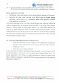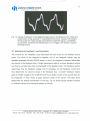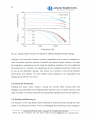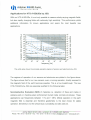
1
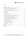
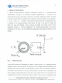
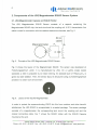
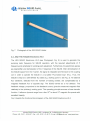
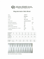
~
I. Jülichersaule
,~
GmbH
Sensortechnik
~
User Manual
for
JSQ Magnetometer SQUID and Electronics
The Jülich SQUID Company (JSQ)
"Manufacturer of
the world' s finest
HTS-rf-SQUIDs"
licensed by
Research Center Jülich
(Forschungszentrum Jülich GmbH)
2
~
'
Jt
Jülicher S UID GmbH
Sensortechnik
Contents
1. SQUID Fundamentals ..
3
2. Components of the JSQ Magnetometer SQUID Sensor System
6
2.1. JSQ Magnetometer Capsule and SQUID Holder
6
2.2. JSQ HTS-rf-SQUID Electronics V4.0
7
2.3. JSQ Tiger Controller for JSQ SQUID Electronics V4.0
9
2.4. Power Supply
10
3. SQUID Operation
11
3.1. Electrical connections
11
3.2. Cooling ..
13
3.3. Installing the JSQ SQUID Sensor Software on your PC
13
3.4. Starting the JSQ SQUID Sensor Software on your PC
13
3.5. Adjustment of the SQUID operating point
14
3.6. Locking the SQUID Magnetometer for Measurement
16
3.7. Adjusting the Feedback Loop Parameters
17
3.8. Saving the Parameters
18
3.9. Quitting and Warming up
18
4. Troubleshooting during SQUID Operation
20
4.1. Radio Frequency Interference
20
4.2. Flux trapping
20
Applications for HTS rf-SQUIDs by JSQ
Products
21
23
How to contact JSQ
24
Phone: +49
Jülicher SQUID GmbH (JSQ) . Lankenstr. 29 . D-52428 Jülich, Germany
+49 - 24 61 61 46 73 . E-mail: [email protected] . www.jsquid.com
- 24 01 - 60 54 87 . Fax:
-
_H-
~
j,
--
U
---
--
-------
--
-----------
3
Jülicher S UIDGmbH
~
Sensortechnik
1. SQUID
Fundamentals
A SQUID (Superconducting QUantum Interference Device) is a superconducting
interferometer, serving as an extremely sensitive magnetometer. It is formed by a
superconducting loop incorporating a weak link, a so-calied Josephson junction. The laws
of physics demand that the magnetic flux enclosed bya superconducting ring is quantized,
<I>= n <1>0,
n = O,:t1,:t2,... . Changesof the externalmagneticfield are compensatedfor by
a variation of the superconducting current around the ring. In the case of a weak link
within the ring, this shielding current, however, is limited. The critical current of the
Josephson junction, le, its Ohmic resistance in the normalconducting state, RN, and the
inductance of the ring, L, are the fundamental parameters governing the behavior of the
SQUID.
rf Ose.
u
L
Ic, RN
Flux
c
Tank eireuit
<Pext
Fig. 1. rf SQUID principle.
The SQUID is read out inductively by means of a tank circuit, a LC resonance circuit
operated close to its rf resonance. By means of a VCO (voltage controlled oscillator), the
operating frequency of the tank circuit is adjusted. The tank circuit is inductively coupled to
the SQUID. The amplitude Irfof the bias currentappliedto the tank circuitis regulatedby a
VCA (voltage controlled attenuator). If the bias current of the tank circuit is increased, the
voltagedrop Urf acrossthe tank circuitis also increased.If the currentIrfis sufficientlyhigh
JOlicher SQUIO GmbH (JSQ) . Lankenstr. 29 .0-52428
Phone:
+49
- 24
01
- 60
54 87
. Fax:
+49
- 24
61
- 61
46 73 . E-mail:
JOlich, Germany
[email protected]
. www.jsquid.com
4
~
'I t
Jülicher S UID GmbH
Sensortechnik
to cause the first flux jump, then Urf does not rise further. A plateau in the Urrlrr
characteristics is formed, because the energy needed to change the magnetic flux is
delivered by the tank circuit.
Urf
<I> ext
= (n+ %)<1>0
~,.~--/ i
ilU
/
OFFset
!
= n<l>o
Iadjustment
VCA
aClju~tment
r
b
Irf
Fig. 2: U - I - characteristics of an rf SQUID.
Depending on the externally applied flux, this point is reached at different values of the
current Irf (point A and B in Fig. 2), and the plateau is formed at different values of Urf. In
order to be able to further process this voltage electronically, it is necessary to choose the
amplitude Irfof the bias current such that the emergingvoltagedifferenceßU accordingto
the external applied flux becomes maximum. This can be achieved if the amplitude Irf of
the bias current is adjusted so that the Urrlrrcharacteristic line takes the shape of a
plateau for any external flux (e.g. le in Fig. 2). The amplitude Irf of the bias current is
adjusted by means of the VCA control (Fig. 16). From the U - I - characteristics of an rf
SQUID (Fig. 2), the U -
<I>
- characteristics,the so-calied transfer function (Fig. 3), is
derived. The transfer function is a periodic function if the magnetic flux threading the
SQUIDloop,with the magneticflux quantum<1>0 denotingthe periodicityconstant.
JOlicherSQUID GmbH (JSQ) . Lankenstr. 29. D-52428 JOlich,Germany
Phone: +49
- 2401
- 605487. Fax: +49- 24 61 - 614673. E-mail:[email protected]. www.jsquid.com
~
j,
5
Jülicher S UID GmbH
~
Sensortechnik
Urf
i\U
0
Fig. 3. U -
<1>
-
2<1>0
<1>0
<l>ext
characteristics (transfer function) of an rf SQUID. The transfer function is
periodic in the magnetic flux quantum <1>0.
Adenotes
the working point (see text).
The JSQ SQUIDs use an inductively coupled tank circuit (Fig. 4). With this design, the
tank circuit noise is minimized and the quality factor Q of the tank circuit is maximized. An
important advantage of this concept is that no galvanic connection from the electronics to
the SQUID, therefore static discharges pose no threat to the SQUID's life. A 50 Q
transmission line connecting the readout electronics with the SQUID is terminated by a
coupling coil adjacent to the SQUID and its tank circuit. The coupling coil serves two
purposes: applying the pumping radio frequency to the SQUID's tank circuit and
generating the feedback flux. In order to linearize the transfer function (Fig. 3), the SQUID
is operated in a so-calied flux-Iocked loop: The SQUID is kept at a well-defined external
flux state (Iocked at a working point A, see Fig. 3) by generating a magnetic feedback field
compensating all measured external flux variations.
50n
cable
coupling
coil
tank
L circuit
Fig.4.
Tank circuit concept.
Phone: +49
Jülicher SQUID GmbH (JSQ) . Lankenstr. 29 . D-52428 Jülich, Germany
. Fax: +49 - 24 61 - 61 4673 . E-mail: [email protected] . www.jsquid.com
- 2401 - 605487
6
~
j 'tJülicher
S UIDGmbH
Sensortechnik
2. Components of the JSQ Magnetometer SQUIDSensor System
2.1. JSQ Magnetometer Capsule and SQUID Holder
The JSQ Magnetometer SQUID Sensor consists of a capsule containing the
MagnetometerSQUIDchip,the tank circuitand the couplingcoil.A 50 Q transmissionline
cable is used for connection with the readout electronics channels, see Fig. 5.
500"
----
cable
Mag netometer
Fa
c
Fig. 5. Principle of the JSQ Magnetometer SQUID Sensor.
Fig. 6 shows the layout of the Magnetometer SQUID. The sensor was developed at
Forschungszentrum Jülich. It is manufactured by JSQ. On a LaAI03 single crystal
substrate, a ditch is prepared by ion beam etching. An epitaxial layer of YBa2Cu307-xis
grown by laser ablation.Then, the sensor layoutis structuredusing a photolithographical
process in a clean room environment.
Fig. 6. Layout of the SQUID Magnetometer.
In order to protect the superconductingYBCOthin filmfrom moisture and other harmful
substances, the JSQ SQUID is encapsulated in a sealed package. The sensor package
consists of a magnetometer, the corresponding tank circuit, the coupling coil and the
coaxial connecting cable. Fig. 7 shows the SQUID holder with the SQUID Capsule
mounted at the end.
Phone:
+49
- 24
JOlicher SQUID GmbH (JSQ) . Lankenstr. 29 . D-52428 JOlich, Germany
01 60 54 87 . Fax: +49 - 24 61 - 61 46 73 . E-mail: [email protected] . www.jsquid.com
-
- j 't
Fig.7.
7
Jülicher S UID GmbH
Sensortechnik
Photograph of the JSa saulD Holder.
2.2. JSQ HTS-rf-SQUID Electronics V4.0
The JSa SaUID Electronics V4.0 (see Photograph, Fig. 8) is used to generate the
pumping radio frequency for saulD
operation, with the required adjustments of rf
frequency and amplitude for working point adjustment. Furthermore, the electronics serves
as preamplifier and demodulator of the rf response of the saulD. After demodulation of
the SaUID signal from the rf carrier, the signal is integrated and fed back to the coupling
coil in order to operate the SaUID in a so-calied "Flux-Iocked loop" (FLL). Thus, the
SaUID is kept at a well-defined flux state (e.g. working point A, see Fig. 3). All external
flux variations, detected from the moment of locking onward, are compensated by a
magnetic feedback flux of opposite sign. The saulD
serves as a null detector. The
feedback voltage, proportional to the feedback current, gives the measured magnetic field
relatively to the (arbitrary) working point. This operating principle ensures a linear transfer
function. It allows a dynamic range from a few 10-5to about 103magnetic flux quanta with
excellent linearity.
Fig. 9 depicts the functional block diagram of the JSa SaUID Electronics V4.0.
Jülicher SQUID GmbH (JSQ) . Lankenstr. 29 . D-52428 Jülich, Germany
Phone: +49 - 24 01 - 605487 . Fax: +49 - 24 61 - 61 4673 . E-mail: [email protected] . www.jsquid.com
8
~
'
S UID GmbH
J t Jülicher
Sensortechnik
Fig.8. Photographof the JSQ HTS-rf-SQUID Electronics V4.0.
.r'
! (inr
~J)pt
<;
i:.
V'
.e<" <'
pr
<::>
..,,,,,
;;
.Hp!.
,,'. :'p' "
'0'
'Y"!"')o' '
~
D
fL
7""
."
Il"'r:.;j
~!
. \b~
,
".,
"".",.
-m.
.n',,1.;\' ."
..
9
f'
'
:;
k(rh", '"
6' "',,,,.~
",c, m..,
i 'ej.(:I"",,
~"
~\','...h"
",' .hm
""
,)
n
:;' Jt:,
(j
,...>C'
f';
]
I,,,,, 'i
I
:::i
)
,.,
.->
."',
u
.",
'In'," ,~:u 'T
,.."
[Ci,. .
Squld
KANAL
Fig. 9. Schematic of the JSQ V4.0 electronics.
Jülicher SQUID GmbH (JSQ) . Lankenstr. 29 . D-52428 Jülich, Germany
Phone: +49 - 24 01 - 60 54 87 . Fax: +49 - 24 61 - 61 46 73 . E-mail: [email protected] . www.jsquid.com
--
~
'j t
---
-
-
--
--
---
-
-
---
9
Jülicher S UID GmbH
Sensortechnik
Fig. 10 and Table I denote the parameter adjustment range of the JSQ rf-SQUID
electronics V4.0.
Table I. Specifications of the JSQ HTS-rf-SQUID Electronics V4.0.
RF-power output.
-75 dBm to -115 dBm (adjustable)
frequency
. 630 MHz to 970 MHz (adjustable)
signal output ampl.
.:t1 0 V
test
output ampl.
. < 1 Vpp
mod. output ampl.
. < 1 Vpp
1000
950
900
N
J:
850
~
>.
0
C
0>
:J
cO>
"Li.
800
750
--------------
700
650
600
0
1000
3000
2000
VCO
4000
value
Fig. 10. Typical calibration curve of a JSQ SQUID Electronics V4.0.
2.3. JSQ Tiger Controller for JSQ SQUID Electronics V4.0
The JSQ Electronics V4.0 is operated and remote-controlled by means of a micro
controller, the JSQ Tiger Controller. The Tiger Controller is integrated with the electronics
(see Fig. 11). It is based on the "Tiger" micro controller chip by Wilke Electronics, Aachen.
JOlicherSQUID
Phone:
+49
-
24 01
-
60 54 87
GmbH
.
Fax:
(JSQ)
+49
-
. Lankenstr.
29
24 61 61 46 73
-
. D-52428
. E-mail:
JuUch,
Germany
[email protected]
. www.jsquid.com
10
~
J'
Jülicher S UID GmbH
~
Sensortechnik
The working point of the Magnetometer saulD sensor is stored in non-volatile memory. In
addition, the "Tiger" micro controller handles the communication to a user front-end
(personal computer) via its RS 232 port (serial port, COM1 or COM2, V.24 protocol).
"'L
'"wd
V4.Q
,<"".
",!"ktnHHh
T'"."..<:><>"«,,,,,,,,,,
~C!
,
Fig. 11. JSa Tiger Controllerfor saulD Electronics V4.0.
2.4. Power Supply
Fig. 12 displays the power supply for the JSa Tiger controller, to be plugged into a 230 V,
50 Hz outlet after completing the electronic wiring according to chapter 3.1.
Fig. 12. Power Supply for the JSa Tiger Controller.
Phone: +49
- 24
Jülicher SQUID GmbH (JSQ) . Lankenstr. 29 . D-52428 Jülich, Germany
01 - 60 54 87 . Fax: +49 - 24 61 - 61 46 73 . E-mail: [email protected] . www.jsquid.com
---------
~
'j ~
11
Jülicher S UID GmbH
Sensortechnik
3. SQUID Operation
3.1. Electrical connections
Prepare all electrical connections according to Figs. 13 and 14. The power supply must
not be connected to 230 V until all other cables are in place and checked carefully!
Oscilloscope
~x
y
Out
Mod.
JSQ Tiger
Controller
for V4.0
Ch. 3
Ch. 2
JSQ rf SQUID
Electronics
V4.0
Ch.1
Power
Cryostat
Power
supply
+/-15V
230 V
50 Hz
Magnetometer SQUID
Fig. 13. Sketch of the electrical connections for SQUID operation.
Fig. 14. Photograph of the electrical connections for SQUID operation.
Jülicher SQUID GmbH (JSQ) . Lankenstr. 29 . D-52428 Jülich, Germany
Phone:+49 - 24 01 - 60 54 87 . Fax: +49 - 24 61 - 61 46 73 . E-mail:[email protected]
. www.jsquid.com
- -
--
--
-
--
---
n
- -
--
- --
-
-
--
- - - -- - --
-- -
-
-
12
~
--
n
- -n
_n
-
-
'
S UID GmbH
J tJülicher
Sensortechnik
The electrical connections should be made as folIows:
1. For SQUID operation, the coaxial cable of the JSQ Magnetometer SQUID Sensor
has to be connected to the SMA socket of the JSQ SQUID Electronics V4.0.
Connect the JSQ rf SQUID Electronics V4.0 with the JSQ Tiger Controller using the
serial cable with DSUB9 connectors.
2. Connect the DSUB9 (female) connector of the Data cable with the JSQ Tiger
Controller. Connect the other side (male DSUB9 connector) with the serial COM
port of your PC. Connect the 3-pin power connector of the JSQ power supply with
the corresponding power jack of the JSQ Tiger Controller.
3. Connect the "Signal out" connector (coaxial LEMO jack) of the JSQ Tiger controller
with the vertical y channel of a standard oscilloscope. Connect the "Modulation out"
connector (coaxial LEMO jack) of the JSQ Tiger controller with the horizontal x
channel of a standard oscilloscope (see Fig. 15). The oscilloscope should be
switched to the x-y-mode for SQUID working point adjustment.
4. Make sure that all connections are made according to Fig. 13. Plug the power cable
into a 230 V 50 Hz outlet.
5. Allow for at least 5 min., better 10 - 15 min. of warm-up time for the electronics
(and cool-down time for the SQUID, see Chapter 3.2) before adjusting the SQUID's
working point (see Chapter 3.5). Otherwise, the working point of the SQUID will drift
during the warm-up phase and readjustments of VCO and OFFset will be
necessary.
Fig. 15. LEMO connectors for visualization of the SQUID test signal with an oscilloscope.
JOlicher SQUID GmbH (JSQ) . Lankenstr. 29 . D-52428 Jülich, Germany
Phone: +49 - 24 01 - 60 54 87 . Fax: +49 - 24 61 - 61 46 73 . E-mail: [email protected] . www.jsquid.com
I
'
~ .~
Jülicher
S UID GmbH
13
Sensortechnik
It is possible to operate up to three SQUID channels simultaneously by the Tiger controller
if more JSQ rf SQUID Electronics V4.0 front ends are connected to the controller.
3.2. Cooling
The SQUID holder has to be operated immersed in liquid nitrogen. Allow for at least 5
min., better 10 - 15 min. of cooling time for the SQUID before adjusting the SQUID's
working point (see Chapter 3.5).
Ensure that the cryostat and the connecting cable to the electronics are completely
enclosed by a metallized rf shield which is connected to the electronics ground (chassis).
If this precaution is not being observed, SQUID operation may be strongly disturbed or
even prevented by rf interferences from the environment.
3.3. Installing the JSQ SQUID Sensor Software on your PC
In case of first operation or in case the PC is changed, the JSQ SQUID Sensor Software
has to be installed on the PC. Insert the JSQ SQUID Sensor CD and copy the folder
"JSQ-SQUID-Program" to your hard disko It is advisable to create a shortcut on the
desktop and/or in the list of programs. The software configures the serial RS232 COM port
to a data transfer rate of 19200 Baud, 8 data bits, parity N, 1 stop bit, flow control
Hardware. In case the Tiger controller is not connected to the serial port "COM 1", please
open the file "DuoSensor.ini" with any editor and enter the port number you are using in
line three, e.g. "PortNum=2" for serial port "COM 2".
3.4. Starting the JSQ SQUID Sensor Software on your PC
Execute the file "DuoSensor.exe" on your PC. Upon starting, the data of the working point
of the Magnetometer SQUID is read from the non-volatile memory of the Tiger Controller
via the RS232 connection. This reading is equivalent to a loading operation when pressing
the "Load" key. In case of successful transfer, the values appear on the Software panel
(Fig. 16) within a few seconds, and the slide controls for VCA, VCO and Offset and the
settings for the Flux-Iocked loop parameters are set accordingly.
If this is not the case, one should check all cable connections and ensure that the power
supply is connected to the JSQ SQUID Electronics.
Phone: +49
JOlicher SQUID GmbH (JSQ) . Lankenstr. 29 . D-52428 JOlich, Germany
+49 - 24 61 - 61 46 73 . E-mail: [email protected] . www.jsquid.com
- 24 01 - 60 54 87 . Fax:
14
~
'I ~
Jülicher S UID GmbH
Sensortechnik
Check the "active" check box of those electronic channels with a saulD connected. Make
sure that those channels that do not have a saulD connected are not checked. Otherwise
the "Auto Reset" function will not work properly because the electronics controller will try to
lock an open loop, leading to continuous resets.
,,,.,'
JSQ Duo Sensor Controt
.
1-11 L11[xl
"'.
YCA yeO
OFF
seled:) Channel1 :r,ar ,ei2 r 11149'"(1505-, 12075'"
F
adive:
r"
on
YCA: J1149
~
31
.
.
'
.
~
. :~,
.';1"::'1.)
v'IJ'~
yeo: 11505
.31
off
~".:>r'''i
~, I
..
'"
l'~E;
"-
Offset .12075
I
Integr-C:47()OpF
I
~.':JI ~ !]1~!OpF3
FB-R:J 3k
.
..:.fj 5k
..:1.
I
.
I
I
,.j;
I
Test
Measure I fiesel
~
I
~
I
J
~
I
~l
I
rl
2ave Param
!.oad
J
Par am
1;
1
I
.Q.uil
J
I~J
I
~rJ ~..J
Fig. 16. Panel of the JSa SaUID Sensor Software
3.5. Adjustment of the SQUID operating point
The controls of the JSa saulD Electronics V4.0 with Tiger Controller have been factoryadjusted to the operating point of the saulD Magnetometer. Upon starting of the software
JOlicherSQUID GmbH (JSQ) . Lankenstr. 29 . D-52428 JOlich,Germany
Phone: +49
- 24 01 - 60 54 87 . Fax: +49 - 24 61 - 61 4673 . E-mail: [email protected] . www.jsquid.com
~
' JOllc.her
SQUID
jt
15
GmbH.
Sensortechnik
(or upon pressing the "Load" button), the working point parameters are read from the nonvolatile memory of the Tiger Controller. Slight re-adjustments may become necessary in
order to achieve optimum performance, or to compensate for changes of the ambient
temperature of the electronics.
The VCO (voltage controlled oscillator) slide control is used to adjust the frequency of the
tank circuit inductively coupled to the SQUID. The VCA (voltage controlled attenuator)
slide control regulates the amplitude Irfof the bias current applied to the tank circuit.
.
.
switch electronics to "Test".
.
Adjust VCA slide controlto a valueof about 1000.
.
Adjust VCO slide control to achieve maximum peak-to-peak signal. If several
switch the oscilloscope to x-y mode and the vertical y-channel to AC coupling.
maxima are seen, then choose the one with the largest amplitude.
.
Adjust VCA slide control to maximum peak-to-peak signal. (Fig. 17)
Fig. 17. Typical Oscillogram of the Magnetometer Test Signal during operation in
unshielded environment. Due to the ambient 50 Hz power line noise, one does not
obtain a standing picture. The triangular shaped transfer function is continuously
shifted horizontally, modulated by the ambient 50 Hz disturbances.
Jülicher SQUIO GmbH (JSQ) . Lankenstr. 29 . 0-52428 Jülich, Germany
Phone: +49 - 24 01 - 605487 . Fax: +49 - 24 61 - 61 4673 . E-mail: [email protected] . www.jsquid.com
16
~
'
SQUID GmbH.
J ~Jülicher
Sensortechnik
Fig. 18. Typical Oscillogram of the Test Signal inside magnetic shielding. If the ambient
50 Hz power line magnetic fields are small enough, a standing picture is obtained.
Manual adjustment of the Offset:
.
Oscilloscope: Check zero position of the y channel. Switch y channel to OC coupling.
.
Using the OFF slide control, the level of the SQUIO signal is adjusted exactlv
symmetrie to the zero level. For a subsequent stable SQUIO operation, a precise
offset adjustment is important.
If the offset is adjusted too low or too high, the SQUIO signal may drift to the limits of this
range of voltage supply. By using the OFFset controller, a fine tuning of the offset is
feasible in order to adjust the SQUIO signal exactly in the central region between the
limits. If the signal reaches the limits, the "Reset" button should be pushed. and the
OFFset slide control must be fine tuned. (In most cases, this can be avoided by adjusting
the offset of the modulation signal very precisely to the central position, before switching
from test signal to operation signal.)
3.6. Locking the SQUID Magnetometer for Measurement
.
Switch the oscilloscope to the time diagram mode, displaying the y channel as
a function of time. Set channel y to OC coupling. Set the y range to allow for
voltagesup to :1:10 V.
.
switch electronics to "Measure/Reset".
In case one does not obtain a stable locked signal, especially in case the signal runs off
and remains either at +10 V or at -10 V, one should press "Measure/Reset" again. The
precise adjustment of the OFFset is of great importance for obtaining a stable locked
state. It might be necessary to readjust the OFFset manually according to the procedure
described in chapter 3.5.3.
Phone:
+49
- 24
Jülicher SQUID GmbH (JSQ) . Lankenstr. 29 . D-52428 JOlich,Germany
01 - 60 54 87 . Fax: +49 - 24 61 - 61 46 73 . E-mail: [email protected] . www.jsquid.com
- j 't
17
Jülicher S UID GmbH
Sensortechnik
Fig. 19. Typical Oscillogram of the Magnetometer signal in the Measurement mode (fluxlocked loop) during operation in unshielded environment. Usually, the ambient
50 Hz power line noise strongly dominates the observed signal in unshielded
environment. Switching the oscilloscope to Une Trigger, one obtains a (quasi)standing picture.
3.7. Adjusting the Feedback Loop Parameters
The controls for the Feedback Loop Parameters are also found on the software control
panel. The value of the integrator's capacitor and of the feedback resistor may be
adjusted separately for each saulD sensor. In short, the integrator's capacitor determines
the velocity of the feedback loop. A larger capacitance leads to a slower feedback velocity
and thus to a smaller slew rate and bandwidth of the feedback loop. The feedback resistor
determines how the feedback voltage (:t10 V) translates into the feedback current and
thus determines the dynamic range of the feedback loop. A smaller feedback resistor
gives a smaller voltage-to-flux coefficient and thus a larger number of flux quanta that can
be measured, in other words a larger dynamic range of the sensor. The Gain factor
determines the internal amplification of the loop. Fig. 20 shows typical transfer functions
for different values of the feedback resistor of the loop.
.
Phone:
+49
- 24
Jülicher SQUID GmbH (JSQ) Lankenstr. 29 . D-52428 Jülich, Germany
01 - 60 54 87 . Fax: +49 - 24 61 - 61 46 73 . E-mail: [email protected] . www.jsquid.com
18
~
I' Jülicher
S UID GmbH
.t
Sensortechnik
100
-
......
<
>
.......
-
10
Cl)
"U
:J
~~rs
1
CL
E
0.1
0 I- ......
0
-R1
-R2
.......
Cl)
Cf)
co
.c.
~
~
~
-50
t"
-R4
-R6
a..
-1 00
100
-RB
1000
10000
Frequency [Hz]
Fig. 20. Typical transfer function of a SQUIDfor different feedback resistor settings.
Intuitively,one would then choose a minimum capacitance and a minimum resistance in
order to achieve maximum slew-rate, bandwidth and dynamic range. However, the larger
the integrator's capacitance and the larger the feedback resistance, the more stable the
flux-Iocked loop isoTherefore, the capacitance and the resistance should be chosen only
so low as the application requires. One should try to achieve a compromise between
performance and stability. The JSQ default factory settings for the capacitance and
resistance are 4700 pF and 10 kO.
3.8. Saving the Parameters
Pressing the "Save" button results in saving the currently active working point and
feedback loop parameters of the MagnetometerSQUIDto the non-volatilememory of the
Tiger Controller. The saved values willbe automatically activated upon the next power-up.
3.9. Quitting and Warming up
The execution of the JSQ SQUID sensor Software is ended by simply pressing the "Quit"
button or by closing the window. There is no Message Box reminding to save changes in
Phone: +49
- 24
Jülicher SQUID GmbH (JSQ) . Lankenstr. 29 . D-52428 Jülich, Germany
01
- 60 54 87 . Fax: +49 - 24 61 - 61 46 73 . E-mail:[email protected]. www.jsquid.com
-- --
~
'j t
--
- u-
-- -
-- - -
- --
-
--
- -- - - u
- -- - - - - - u
-
- u-
-
-
- -
--
- -- --
--U
- --
- -
Jülicher S UID GmbH
19
Sensortechnik
the settings of the SQUID parameters. Unsaved working point and feedback loop
parameters are lost. However, the factory settings in conjunction with the "Fast Adjust"
upon power-up and warm-up usually suffice to find the working point again.
The JSQ SQUID capsule is not sealed. Therefore, special care has to be taken when
taking the SQUID out of the liquid nitrogen. The SQUID should be carefully warmed in the
warm air of a blowdryer. Check with your hand that the air at the SQUID location is not too
hot, otherwise the SQUID may be damaged. Condensing water on the outside of the
SQUID capsule should be wiped off when the SQUID is warming up.
JOlicher SQUID GmbH (JSQ) . Lankenstr. 29 . D-52428 JOlich, Germany
Phone: +49 - 24 01 - 60 54 87 . Fax: +49 - 24 61 - 61 46 73 . E-mail: [email protected] . www.jsquid.com
20
~
4. Troubleshooting
SQUID GmbH..
j 'tJülicher
Sensortechnik
during SQUID Operation
4.1. Radio Frequency Interference
A well-known problem in case of SaUID operation in unshielded environment is the
degradation of performance due to environmental Radio Frequency Interference. RF
Interference results in a reduction or even suppression of the transfer function of the
SaUID which can be observed in the "test"mode.JSa suggeststo operatethe saulD
package in a well-grounded metal container, e.g. a cylinder of thin aluminium or lead foil, if
the environmental high frequency noise is unacceptably high.
4.2. Flux trapping
Another well-known problem in case of saulD operation in unshielded environment is flux
trapping due to large external field amplitude changes. Flux trapping results in
spontaneous signal jumps due to fluxvortex hoppingwithinthe superconductingthin film,
the so-ca lied "shot noise". An increased 1ff noise can be observed, in extreme cases,
SaUID operation can be jeopardized. Warming up the SaUID and releasing the trapped
flux solves this problem.
Phone:
+49
- 24
JOlicherSQUID GmbH (JSQ) . Lankenstr. 29 . D-52428 JOlich, Germany
01 - 60 54 87 . Fax: +49 - 24 61 - 61 46 73 . E-mail: [email protected] . www.jsquid.com
~
'j t
21
Jülicher S UID GmbH
Sensortechnik
Applications for HTS rf-SQUIDs by JSQ
With our HTS-rf-SQUIDs, it is not only possible to measure slowly varying magnetic fields,
but also rapidly changing fields with extremely high sensitivity. This performance yields
additional information for known applications and opens the road towards new
applications.
!;'
-
1011
108
I
1010
107 3
!;;
109
106 <C
:J
E
108
105
N
:J
~
()
107
~
106
e/)
1
.~
()
103
-
r.......
104
103
102
5
0
104
"C
Q)
101
-~
er
$2.
Q)
.g
100 e=
a.
~
Q) 102
c:
10.1 CD
~
101
E
100
10.1
10.2 S'
-I
100
101
102
frequency
103
104
105
10-3 .......
106
[Hz]
The white area shows the principle operation regime of sensors and electronics by JSQ.
The regimes of operation of our sensors and electronics are plotted in the figure above.
The figure shows that for our new sensors, even a moving operation, directly exposed to
the magnetic field of the earth becomes possible. This is a true breakthrough. The new
HTS-rf-SQUIDs by JSQ are especially qualified for the following tasks:
Non-Destructive Evaluation (NDE) of materials (Le. detection of flaws and cracks in
airplane parts or checking steel reinforcement buried inside concrete structures). These
applications use frequencies between 1 Hz and 1 MHz. Mobile operation in the earth
magnetic field is essential and therefore gradiometry is the best choice for stable
operation. Sensitivity is not the critical issue, but stability and slew rate are.
Phone:
+49
- 24
Jülicher SQUID GmbH (JSQ) . Lankenstr. 29 . D-52428 Jülich, Germany
01 - 60 54 87 . Fax:
+49 - 24 61 - 61 46 73 . E-mail: [email protected]
. www.jsquid.com
22
~
j 'tJülicher
S UID GmbH
Sensortechnik
Geological surveying needs a very high bandwidthfrom 0.001 Hz up to 105 Hz and a
high sensitivity, while directly exposed to the full earth magnetic field. The problem of
moving within the earth field is less important, because normally the sensors are not
movingduring operation. Instead they are securely positionedand fixed in a small hole,
dug into the ground.
Biomagnetic diagnostics, especially of the heart functions and the brain need the
highest sensitivity, but use a small frequency range (0.01 Hz up to 300 Hz). With a
sensitivity limitbelow 30 ff/v'Hz, our new HTS-rf-SQUIDsare exceptionally weil suited for
cardiac measurements. Even Fetal Magnetocardiography has been shown feasible with
our SQUIDs.
Phone: +49
- 24
Jülicher SQUID GmbH (JSQ) . Lankenstr. 29 . D-52428 Jülich, Germany
01 - 60 54 87 . Fax: +49 - 24 61 - 61 46 73 . E-mail: [email protected] . www.jsquid.com
~
I' Jülicher
S UID GmbH
~t
Sensortechnik
23
Products
SQUIDs by JSQ are very easy to handle, radiofrequency (rf) driven sensors for extremely low
magnetic fields (present limit: 20 fT/vHz) and magneticfield gradients «
1 pT/cmvHz).These
sensors are very fast. Therefore, arealtime measurement of rapidly changing magnetic fields (up
to 1 MHz) becomes possible. The sensor material is superconducting YBaCuO, grown in thin films
by a patented process. During operation, the sensors have to be cooled by liquid nitrogen (or
cryocoolers). Due to the relatively high operation temperature (-198°C) compared to Low
Temperature Superconductors (LTS), this material is called a High Temperature Superconductor
(HTS). The sensors are fabricated by a modern lithographical process. Their unique design is
protected by patents.
JSQ ofters these sensors complete with room temperature drive and read out electronics. The
JSQ electronic control units run at 600 to 1000 MHz. Adjustment of the SQUID's working points is
conducted by a microcontroller integrated with the electronics. The HTS rf-SQUIDs by JSQ are
reliable, with fully guaranteed sensitivity and have demonstrated very stable performance.
Jülicher SQUID GmbH (JSQ) . Lankenstr. 29 . D-52428 Jülich, Germany
Phone: +49 - 24 01 - 60 54 87 . Fax: +49 - 24 61 - 61 4673 . E-mail: [email protected] . www.jsquid.com
24
~
'j t
Jülicher S UID GmbH
Sensortechnik
How to contact JSQ
telephone:
(+ 49) 2401 60 5487
or
fax:
(+ 49) 2461 61 44 31
(+ 49) 2461 61 4673
e-mail:
[email protected]
mail:
JSQ GmbH, Lankenstr. 29,
D-52428 Jülich,
Germany
The JSQ team
Management:
Willi Zander, Simin Krause, Chris Buchal
Design:
YiZhang
Thin Film Technology:
Jürgen Schubert
Fabrication:
Marko Banzet
Electronics & Computing:
Ralph Otto, Norbert Wolters, Dieter Lomparski
Systems:
Hans-Joachim Krause
Machine Shop:
Hans Wingens
Shipping:
Manfred Plum
Please visit our website at: http://www.jsquid.com
Jülicher SQUID GmbH (JSQ) . Lankenstr. 29 . D-52428 Jülich, Germany
Phone:
+49
- 24
01
- 60
54 87 . Fax:
+49 - 24 61 - 61 4673
. E-mail:
[email protected]
. www.jsquid.com
I'
J~
~
Jülicher
SQUID GmbH..
Sensortechnik
Data Sheet
Magnetometer
Date:
19.09.07
SQUID:
Standard
Washer:
03.5
mm
Loop:
100 x 100
J.lm2
Tank circuit
Lumped element
Resonance frequency:
731
MHz
Coupling (rf absorption):
-26
dB
Quality factor:
340
SQUID signal amplitude:
0.6
Vpp
Transfer coefficient at R1 = 10 kQ
0.195
V/(JJo
Calibration:
9.3
nT/(JJo
FeedbackResistor
R [kQ]
Transfer
coefficient
[mV/(JJol
R1
R2
R3
R4
R5
R6
R7
R8
1
3
6
10
15
20
50
100
21
60
120
195
290
380
950
1900
C1
0.33
Integr-C
C [nFl
C2
1
C3
2.2
I,
I
t- -+-
-+-+-
- r--
I
I
!---
oe
-'--
i
f
C5
10
C6
22
+
-!--'-
+
.
r
Open laap SQUID signal in shielding
----
~
--
- t-+-
+-+
C4
4.7
,-+t
f
I
"---t---
~
~
-
C7
100
Steuerbefehle für SQUID-Elektronik
Befehl
über die RS232-Schnittstelle
A 1 :value;
F1 :value;
On :value;
R1 :k;
C1 :/;
ZA 1 :i;
ZAR 1:i;
Mon;
Moff;
Beschreibung
Setze Attenuation
value = 0..4095
Setze Frequenz
Setze Offset
Setze Feedback Widerstand
k = 1..8
1=
1..7
Setze Integrator C
i
=
0 = off
Setze Kanal-Freigabe
Setze Autoreset
Setze Modulation ON (alle Kanäle)
Setze Modulation OFF (alle Kanäle)
S;
L;
WARMUP;
Save Oata
Load Oata
Restart Program
BO:k;
Eon;
Eoff;
Setze Baudrate
Setze ECHO ON
Setze ECHO OFF
Zm;
Tm;
Km;
Setze Testmodus
Setze Switch Output
Fm;
Am;
FAm;
Suche Resonanz
Adjust Resonanz (Attenuation, Frequency, Offset)
FastAdjust Resonanz
GA;
GF;
GFF;
GO;
GR;
GC;
GAR;
GZA;
Get Attenuation (Kanal 1..4)
Get Frequenz (Kanal 1..4)
Get Frequenz/100 (Kanal 1..4)
Get Offset
(Kanal 1..4)
Get Widerstand (Kanal 1..4)
Get Integrator C (Kanal 1..4)
Get Freigabe
(Kanal 1..4)
Get Autoreset (Kanal 1..4)
>
?>
Normaler Prompt - Erscheint nach Ausführung eines Befehls
Fehler-Prompt - Erscheint nach fehlerhaften Eingabe
SetzeMessmodusI Reset
Kanal n = 1
i = 1 = on
Kanal m = 1 0 = ALL
0 = OFF
Zuordnung der Baudrateneinstellungen
Standard beim Einschalten: 19200 Baud, 8 Oatenbits, 1 Stopbit, HW-Handshake
300 Baud
BO:1;
1200 Baud
BO:2;
2400 Baud
BO:3;
4800 Baud
BO:4;
9600 Baud
BO:5;
19200 Baud
BO:6;
38400
Baud
BO:7;
76800
Baud
BO:8;