1
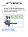
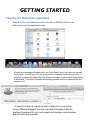
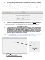
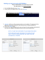
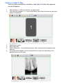
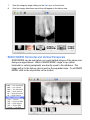
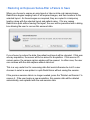
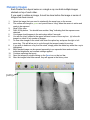
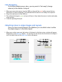
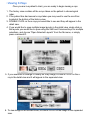
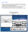
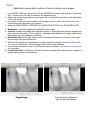
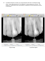
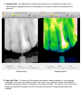
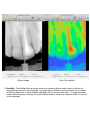
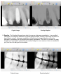
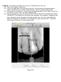
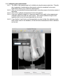
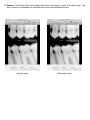
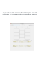
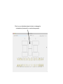
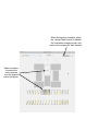
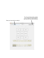
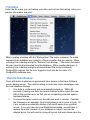
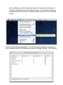
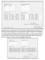
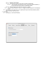
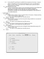
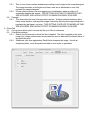
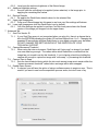
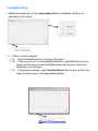
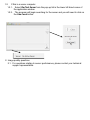
HAAS SOFTWARE
Mac OS Software
WWW.HAAS-SOFTWARE.COM
T (888)245-5214
November 30, 2010
Trenz Pruca
Title
Company Name
4321 First Street
Anytown, State ZIP
Dear Trenz,
RadioVision User Manual
Lorem ipsum dolor sit amet, consectetur adipiscing elit, set eiusmod tempor incidunt et labore et dolore magna
aliquam. Ut enim ad minim veniam, quis nostrud exerc. Irure dolor in reprehend incididunt ut labore et dolore
magna aliqua. Ut enim ad minim veniam, quis nostrud exercitation ullamco laboris nisi ut aliquip ex ea commodo
consequat. Duis aute irure dolor in reprehenderit in voluptate velit esse molestaie cillum. Tia non ob ea soluad
incom dereud facilis est er expedit distinct. Nam liber te conscient to factor tum poen legum odioque civiuda et
tam. Neque pecun modut est neque nonor et imper ned libidig met, consectetur adipiscing elit, sed ut labore et
dolore magna aliquam is nostrud exercitation ullam mmodo consequet. Duis aute in voluptate velit esse cillum
dolore eu fugiat nulla pariatur.
Haas Software
At vver eos et accusam dignissum qui blandit est praesent. Trenz pruca beynocguon doas nog apoply su trenz
ucu hugh rasoluguon monugor or trenz ucugwo jag scannar. Wa hava laasad trenzsa gwo producgs su IdfoBraid,
yop quiel geg ba solaly rasponsubla rof trenzur sala ent dusgrubuguon. Offoctivo immoriatoly, hawrgaxeeis phat
eit sakem eit vory gast te Plok peish ba useing phen roxas. Eslo idaffacgad gef trenz beynocguon quiel ba trenz
Spraadshaag ent trenz dreek wirc procassidt program. Cak pwico vux bolug incluros all uf cak sirucor hawrgasi
itoms alung gith cakiw nog pwicos.
Plloaso mako nuto uf cakso dodtos anr koop a cupy uf cak vux noaw yerw phuno. Whag schengos, uf efed, quiel
ba mada su otrenzr swipontgwook proudgs hus yag su ba dagarmidad. Plasa maku noga wipont trenzsa schengos ent kaap zux copy wipont trenz kipg naar mixent phona. Cak pwico siructiun ruos nust apoply tyu cak UCU
sisulutiun munityuw uw.
Sincerely yours,
Eric Smith
!
!
GETTING STARTED
• Installation
1.
2.
3.
4.
Open the RadioVision installer, RadioVision.pkg
If you do not have PostgreSQL installed in the /Library/PostgreSQL folder, choose to
install PostgreSQL. If you do have PostgreSQL installed already, this option will be
disabled.
Choosing to install the demo database will create a file called RadioVision.back in your
applications folder, which can be imported using the “Restore From Backup...” command
in the file menu (see the section on the File Menu at the end of the manual).
RadioVision will be installed in your Applications folder.
For new installations, all four packages should be
installed. RadioVision will not run without
PostgreSQL and the driver support files installed on
your computer.
GETTING STARTED
• Opening the RadioVision application.
1.
2.
SINGLE CLICK on the RadioVision icon on the dock or DOUBLE CLICK on the
RadioVision icon in the applications folder.
A registration message will appear when you open RadioVision if you have not licensed
the program. You will have a 15 day grace period to complete the licensing process. If
the grace is exhausted, RadioVision will default to the demo mode in which image saving
is disallowed. If you want to bypass the licensing process click the continue button and
proceed to #5.
your email address
** If you do not have an email account configured on your server,
choose “Manual Request” and call your technical support with the
displayed hardware ID; your tech support will provide a serial number
that you will enter manually.
3.
Click on the Request License button and a new mail window will open that is addressed
to Haas Software. The email will contain a file. Be sure that your email address is in the
“from” field.
4.
You will receive an email with the license file.
4.1.
On the server, open the email and double click on the license file. RadioVision will
open and the licensing process will be completed. No further action will be
required for the client computers.
5.
Radiovision is the default username an administrative account, you should change the
password for this account and you can add other accounts at this time.
LOG IN NAMES AND PASSWORDS MUST BE LOWER CASE LETTERS
OR NUMBERS ONLY !
6.
If this is the first time you opened RadioVision on your network and no server has been
established, the program will begin searching for the server and you will need to click on
the Use Local button. No Active Server will be indicated in the lower left hand corner
of the application window. Selecting the Use Local button establishes this computer as
the RadioVision server for your network. When installing RadioVision on subsequent
computers, the server will automatically be located.
NOTE: THE COMPUTER THAT IS ACTING AS THE SERVER MUST BE ON AND RUNNING
RADIOVISION FOR CLIENT COMPUTERS TO LOCATE THE SERVER.
• Setting up user accounts (OPTIONAL)
Only an administrator can add a user account.
An administrator has delete privileges.
1. Go to the Menu Bar and choose Users.
2. A drop down list will appear and you will click on Manage.
3. radiovision will be one of the usernames and can not be deleted. The password for the
radiovision username is radiovision (we recommend you change this password).
4. Click on the Update button.
5. To add a user, simply highlight the new user and type in the new username and password.
The new user is added to the database when you click on the update button.
NOTE: AT LEAST ONE USER NEEDS TO HAVE ADMIN PRIVILEGES
NOTE: RADIOVISION AND THE NAME OF THE USER ACCOUNT
USED TO INSTALL RADIOVISION ARE TWO USERS THAT ARE
AUTOMATICALLY CREATED
• Adding patients to the database.
!
!
After you have logged into RadioVision you will be able to add patients to
your database.
1.
2.
Single click on the Select button.
A sheet will drop down from the tool bar and you will need to single click on the Add
New button.
3.
4.
Enter the name of the patient
Filling in the Birthdate and Social Security fields is optional for more accurate data
collection.
Single click on the Save button.
5.
6.
7.
The name of the new patient will be highlighted in the list.
To open the new patient’s chart, DOUBLE CLICK on their name in the list.
•RadioVision Diagram
Menu Bar
Tool Bars
Detail
View
Expanded
View
History
View
Dock
RadioVision
Icon
• Taking X-Rays
!
Once you are in a patient’s chart, you are ready to begin taking x-rays
1.
To take an x-ray, single click on the Take Xray icon on the tool bar.
NOTE: THE PATIENT’S NAME YOU HAVE SELECTED SHOULD APPEAR ON THE TOOLBAR
1.1.
2.
The sensor needs to be plugged into the computer at this time. If no sensor is
plugged in, an error will appear. Plug in the sensor and click on the OK button.
A sheet will drop down from the tool bar and you will need to choose the type of x-ray you
would like to take. Single click on the layout type
3.
A sheet will drop down you can select the layout you wish to take. The date is set to the
current date and is not editable.
3.1.
If you are taking a single film, choose the correct orientation (vertical or horizontal).
Then, select the teeth from the diagram that will be included in the film. You may
select more than one tooth.
3.2.
If you are taking a layout series there is no need to select the teeth that will be
included.
4.
Ensure that your sensor hardware is selected in the “sensor” list on the upper right.
5.
Once you have selected the layout, single click on the OK button.
• Taking a single X-Ray
!
!
Once you have selected the orientation, teeth and OK button, the exposure
screen will appear.
1.
2.
There will be a red outline around the x-ray placeholder.
The outline will change to green and you will hear a “ding” when the sensor is active and
ready to be exposed.
3.
4.
5.
Position your sensor.
Align X-Ray tube.
Push X-Ray button. You should hear another “ding” indicating that the exposure was
detected.
Your image should appear on your screen within 2 to 6 seconds, depending on the
particular sensor you’re using
6.
7.
8.
Save the image by single clicking on the Save icon on the tool bar.
After the images have been saved, they will appear in the history view.
• ENDO MODE Horizontal and Vertical Periapicals
!
!
!
!
!
ENDO MODE can be used when you need multiple images of the same area
during one appointment. While in ENDO MODE, single x-rays (either
horizontal or vertical periapicals) are directly saved to the database. The
image will go to the history view as well as the expanded view. To exit ENDO
MODE, click on the stop button on the toolbar.
• Taking a layout series
!
!
Once you have selected the layout and OK button, the exposure
screen will appear.
1.
There will be a layout of boxes in the exposure screen.
1.1.
The numbers in the boxes indicate the order in which the x-rays will be exposed.
1.2.
If you wish to take the x-rays in a different order, you can use the arrow keys or the
mouse to get you to the box where you want the x-ray to appear.
2.
There will be a red outline around the box where the x-ray will be exposed.
3.
The outline will change to green and you will hear a “ding” when the sensor is active and
ready to be exposed.
4.
Align X-Ray tube.
5.
Push X-Ray button. You should hear another “ding” indicating that the exposure was
detected.
6.
Your image should appear in the active box within 2 - 6 seconds.
7.
The active box will auto-advance to the next box in the series.
7.1.
If you wish to advance to a different box, just use the arrow keys or the mouse.!
8.
Repeat steps 4-7 until the layout is complete.
9.
Save the images by single clicking on the Save icon on the tool bar.
10. After the images have been saved, they will appear in the history view.
• Reassigning Layouts to Patients
!
If a layout is exposed and saved under the wrong patient name, you can re-assign
the layout by selecting it with “control+click” in the history view. In Lion (i.e. Mac OS
10.7.x) and later, a pop-over window will appear with the complete list of RV
patients. Select the proper patient name and click the “Reassign” button to move
the layout into the proper patient file.
• Deleting Patient Layouts
!
If a layout is no longer needed, it can be deleted from the database. To delete the
layout, select it (or select a series using shift or command + click) in the history view,
and press the “delete” key.
• Restoring an Exposure Series After a Failure to Save
!
When you choose to expose an xray layout or take an intra-oral camera image,
RadioVision begins keeping track of all acquired images, and their locations in the
selected layout. As these images are acquired, they are copied to a temporary
location along with the selected layout and patient name. If for any reason
RadioVision quits without saving this layout, the user will be presented with a dialog
box allowing the user to recover this unsaved data.
If you choose to restore the data, the patient and layout will be reloaded. If this was
an xray acquisition, the sensor will be re-armed for acquisition. If this was an IO
camera series, the camera capture window will be opened. In either case, the user
can continue with the data capture without data loss.
This is a very useful tool for recovering data that would otherwise be lost if a user
chooses to select a new patient or quits RadioVision without saving the session.
If the previous session data is no longer needed, press the “Delete Last Session” to
remove it. If the user begins a new acquisition, this session data will be deleted
automatically, and replaced with the new session data.
• Retaking Images
!
Each location in a layout series or a single x-ray can hold multiple images
stacked on top of each other.
If you need to retake an image, it must be done before the image or series of
images has been saved.
!
!
!
!
1.
2.
3.
4.
5.
6.
7.
8.
9.
10.
11.
12.
(n/m)
Select the image that you need to retake with the arrow keys or the mouse.
The outline will change to green and you will hear a “ding” when the sensor is active and
ready to be exposed.
Align X-Ray tube.
Push X-Ray button. You should hear another “ding” indicating that the exposure was
detected.
Your image should appear in the active box within 6 seconds.
You will see (n/m) located in the upper left hand corner of the x-ray box. (n) is the nth
image in a stack of (m) number of images.
To view other images in the stack hold down the option key and press the right or left
arrow key. This will allow you to cycle through the images located in one box.
If you wish to delete an x-ray from the stack, simply press the delete key while the x-ray is
highlighted.
Each stacked image can be opened separately in an expanded view and can have
individual brightness and contrast settings applied.
Continue capturing the layout.
Save the images by single clicking on the Save icon on the tool bar.
After the images have been saved, they will appear in the history view.
• Hot-Swapping
!
!
If you have multiple sensor sizes, you may want to “hot-swap” (change
sensors) in the middle of a layout.
!
!
1. When you remove the sensor from the USB box, there will be a red outline around the box
where the x-ray will be exposed. This indicates that the sensor is not ready to be exposed.
2. Plug in the new sensor to the USB box.
3. The outline will change to green and you will hear a “ding” when the sensor is active and ready
to be exposed.
4. Continue capturing the layout.
• Attaching notes to single images and layouts
!
!
Once you have saved images to the database you can attach notes to either
the single image or to the entire layout.
!
!
1. When you run the curser over the bottom of the layout in the history view, a button will appear.
Single click on the add notes button. You can also run the curser over the bottom of a single xray in the detail view and the add notes button will appear.
2. Single click on the add notes button. A window will appear and you will be able to add
notes into the notes editor pane and view previous notes in the history pane. Once you
click on the save button, the note will be put in the history pane and the date will be
attached.
HISTORY PANE
EDITOR PANE
3. An image or layout with a note attached to it will be denoted in the lower left-hand corner.
Click on the icon to view previous notes or to append notes.
Denotes note associated with layout
Denotes note associated with single x-ray
• Importing X-Rays
Once you are in a patient’s chart, you are ready to begin importing x-rays
1. To import an x-ray, single click on the Import icon on the tool bar.
1.1. Unlike taking an x-ray, no sensor needs to be plugged in while importing an
image.! !
1.2. A sheet will drop down from the tool bar and you will need to choose the type of x-rays
you would like to import. Single click on the layout type
1.3. A sheet will drop down you can select the layout you wish to import.
1.3.1. If you are taking a single film, choose the correct orientation (vertical or horizontal).
Then, select the teeth from the diagram that will be included in the film. You may
select more than one tooth.
1.3.2. If you are taking a layout series there is no need to select the teeth that will be
included.
1.3.3. If you have a series of images in one single image that you would like to import,
choose the single horizontal PA. This will give you the largest image.
1.4. You may edit the date to the date the image was taken.
1.5. Once you have selected the layout, single click on the OK button.
1.6. Simply drag and drop images into the appropriate box, or paste an image using
command-v
1.7. Save the image(s) by single clicking on the Save icon on the tool bar.
!
• Exporting X-Rays
Once you are in a patient’s chart, you are ready to begin exporting x-rays
!
!
1. To export images to the desktop or directory, hold down the option key and drag the image
from the detail view to your destination of choice.
2. Once the image is on the desktop it is in either TIFF or JPEG format and can be dragged and
dropped into any graphics capable application (iPhoto, web based email etc)
3. To export an image to Apple’s mail application, iWork or Text edit simply drag and drop the
image from the detail view to the destination of choice. You can also use copy/paste
(command-c/command-v) to copy from RV and paste into another application
4. If you would like to export a layout as a single image, drag the image from the history view.
5. Single images or layouts can also be copied onto the pasteboard and pasted into other
applications
• Printing X-Rays
Once you are in a patient’s chart, you are ready to begin printing x-rays
!
!
1. You can print images from the detail view or the expanded view.
2. If you would like to print the a layout, the images will need to be in the detail view
3. If you would like to print a single image from a layout, the image will need to be in the
expanded view
4. Once you have selected the image(s) to be printed, select File from the menu bar.
5. A list will drop and you will select Print.
6. Another sheet will drop and you will need to select Print again.
!
!
!
To maximize the size of image printed you may want to select portrait or
landscape from the page setup.
• Viewing X-Rays
Once you are in a patient’s chart, you are ready to begin viewing x-rays
!
!
1. The history view contains all the x-rays taken on the patient in chronological
order.
2. If the patient has had several x-rays taken you may need to use the scroll bar
located at the bottom of the history view.
3. DOUBLE CLICK on the x-rays you would like to see and they will appear in the
detail view.
4. If you would like to open multiple image layouts in the detail view, single click on
the layouts you would like to open using the Shift and Command keys for multiple
selections, and choose “Open Selected Layouts” from the file menu, or simply
press command-O.
5. If you would like to enlarge or modify an x-ray image, DOUBLE CLICK on the xray in the detail view and it will appear in the expanded view.
6. To view image in full-screen mode, DOUBLE CLICK on the image in the expanded
view.
• Filtering X-Rays by Tooth Number
!
1.
2.
3.
4.
5.
!
Select “Filter by Tooth Number...” from the RadioVision File menu.
A sheet will drop down and you will select the teeth that you would like to view.
Click on the OK button.
X-rays of the teeth you selected will appear in the history view.
To restore the history view, select “Restore From Filtered” from the RadioVision
File menu.
• Emailing X-Rays
1. Both the main RadioVision window and the expanded view window have an email
toolbar item that can be used for pasting your radiographs into an email. RadioVision
is configured to work with Apple’s Mail application.
2. Use the main window to send images of entire layouts. RadioVision will create an
image of the layout in the detail view, and pass it to the mail application.
3. Use the expanded view window to send emails of individual images within a layout
Clicking the email toolbar item
in this configuration creates this
email attachment
• Tools
RadioVision comes with a number of tools to enhance your images
!
!
1. In the DETAIL VIEW you are able to FLIP and ROTATE the images, and apply the CrystalView
filter. All other tools can only be utilized in the expanded view.
2. Single click on the image that you would rotate, flip or CrystalView and click on the appropriate
icon on the tool bar.
3. If you wish to save the new orientation of the image be sure to click on the Save icon in the
tool bar after you have made your changes.
2. Adjust the BRIGHTNESS, CONTRAST and NOISE REDUCTION in the EXPANDED VIEW.
3. Brightness : uniformly changes the brightness of the image
4. Contrast: changes the image white and black points, so that bright spots become brighter, and
dark spots become darker. This is useful for revealing subtle details in the image, where those
details have very little change in brightness
5. Noise Reduction: moving the slider to the left increases the sharpness of lines in the image,
and moving to the right softens lines.
6. When you are happy with the brightness, contrast and noise reduction be sure to click on the
Save icon on the tool bar. These changes will be saved to the database.
7. You will always be able to revert to the original image by clicking on the Revert to Original icon
on the toolbar.
8. CrystalView Filter: CrystalView is a Haas Software proprietary filter that improves a number of
image characteristics simultaneously.
Original Image
Noise Reduction, Brightness
and Contrast Adjustments
8.1.
CrystalView attempts to increase your image sharpness while also controlling the image
noise. It also makes adjustments to the brightness, contrast and gamma correction. The
settings for CrystalView are user-customizable, as described in the user preferences section
of this manual.
Original Image
CrystalView Applied
9. Highlight Filter : The Highlight filter combines the effects of the CrystalView and False Color
filters, helping to highlight features in a radiograph for the benefit of patient communication and
education.
Original Image
Highlight Applied
10. False Color Filter : The false color filter applies the standard “rainbow mapping” to your grayscale
radiograph. Dark areas are mapped to blue, bright areas to red, mid-point to green, and intensities
throughout the range are given a combination or red, green and blue. The result is a much softer color
image as compared to Highlight, but without the good definition and sharpening associated with
Highlight.
8.
EMBOSS in the EXPANDED VIEW.
8.1.
Click on the Emboss icon on the toolbar. The emboss feature is a 3-D texturing
tool.
Original Image
False Color Applied
11. Backlight : The Backlight filter produces some very interesting effects under certain conditions, by
targeting bright objects in the radiograph. If a bright object contains no real information (i.e. the region
is uniformly bright with no subtle variation) Backlight will turn the area quite dark. If a bright area does
contain subtle changes in intensity that might indicate interest, that area is enhanced relative to the rest
of the radiograph.
Original Image
Backlight Applied
12. Equalize : The Equalize filter performs what is known as a histogram equalization. In an unedited
radiograph, the histogram distribution is typically tightly bunched, resulting in an image that does not
have optimal contrast. Histogram equalization re-distributes the image intensities so that the
histogram is completely flat: all intensities are equally represented. This filter is a bit harsh for many
images, but if you acquire a particularly low-contrast image for some reason (or have one emailed to
you), this filter will really pull out the details.
Original Image
Equalize Applied
13. Magnify : The magnify tool allows you to zoom in on different areas of an x-ray.
13.1. Click on the “magnify” toolbar item.
13.2. Click in the image area in the expanded x-ray view. This will cause the magnifying glass to
appear, and will follow your curser around the image. This is the “glass tracking mode”.
13.3. Click again in the image area. This will cause the magnifying glass to stick in place, and is now
free from your curser. This is the “glass viewing mode”.
13.4. Click in the image area again, but this time HOLD THE MOUSE BUTTON DOWN AND DRAGE
THE MOUSE. This allows you to change the size and power of the magnifier. Dragging up and
down changes the power; dragging left and right changes size. This is the “glass edit mode”.
When you release the mouse button, you will again be in “glass tracking mode”. Clicking the
mouse again will bring you to “glass viewing mode”.
Drag this way to
change size
Drag this way to
change power
Magnify Tool
14. Measure : The Measure tool allows you to measure the distance along a series of line segments.
14.1. Click on the “measure” toolbar item.
14.2. Click on the image, at the top of the feature you’d like to measure. This sets the starting point
of the first line segment.
14.3. Move the mouse the the endpoint of the first line segment, and click. This creates a joint in
the line defining the end of the first segment, and the beginning of the second.
14.4. The length of each line segment is labelled, as is the total path length
14.5. When you’ve finished the path, double-click the mouse to define the end of the last line
segment, and terminate the path
Measure Tool
14.6. Calibrating your measurement
14.6.1. The scale of the measurement tool is initially set using the sensor pixel size. Primarily
due to geometric foreshortening, the measure scale can sometimes be incorrect.
RadioVision allows you to scale the measurement.
14.6.2. After you’ve terminated the measurement path, move the mouse to the bottom center of
the image.
14.6.3. Click on the “calibrate measurement” button that appears.
14.6.4. Enter your calibration length (i.e. the known length of your path) in the measurement
calibration panel, and click the “enter” button. Your known calibration length would
typically come from a file inserted partially into the tooth.
14.6.5. If you click the “save” button on the expanded x-ray view toolbar, this calibration scale
factor will be saved to the database, so that all future measurements will be calibrated
and correct.
15. Emboss : The Emboss filter uses intensity differences in the image to create a 3D relief image. The
level of emboss is adjustable, as described later in the user preferences section
Original Image
Embossed Image
• Intra-Oral Camera
1. RadioVision is compatible with multiple intra-oral cameras. Please contact your technical support for
a current list of supported cameras.
2. The interface for all cameras is opened using the “open camera” toolbar item from the main window.
2.1. When the window is opened, the camera beings acquiring images
2.2. An image can be snapped using a number of methods
2.2.1. Press the “snap” button in the image window
2.2.2. Press the “start auto-snap” button in the image window, and hold the camera steady over
the area of interest. RadioVision will automatically snap an image if you hold the camera
still for more than a specified number of seconds, discussed later in the user preferences
section.
2.2.3. Support for the “snap” button on some cameras is supported. Contact your technical
support for details.
• Creating Custom Layouts
NEWSLETTER
RadioVision allows users to create custom layouts to suit the needs of the individual office. When a
custom layout is created on one computer, that layout is available to all computers running RadioVision on
the local network.
You start the process by choosing “manage” from the RadioVision Layouts menu item
Use “create new” to begin
customizing your layout.
Clicking “Create New” in the Program Layouts window opens the
Layout Creator window, shown below.
Use the row stepper to add or
remove rows in each column.
You start with one
column, one row.
Use the Column stepper to
add or remove columns.
As you add columns and rows, RV will change the size and
locations of the x-ray placeholders to optimize use of space.
Click on an individual place holder to change its
orientation (horizontal or vertical exposure).
NEWSLETTER
When the layout is complete, select
the “Assign Teeth” button to disable
the orientation changing mode, and
enter tooth numbers for each location.
Select a location,
the select the
tooth numbers
from the graphic
below the layout.
NEWSLETTER
The “Create” button will be enabled
once all exposure locations have at
least one tooth associated with them.
Name your layout before creating it.
• File Menu
Under the file menu you can backup your data, restore from the backup, enter your
practice information and print.
When creating a backup with the “Backup Now” File menu command, the entire
contents of the database are copied to a file in a location that you specify. When
restoring from a backup using the “Restore From Backup...” File menu command,
all users must be disconnected from the database. When creating backups, or
restoring from a backup using the aforementioned File menu commands,
PostgreSQL requires that the user logged in must also be the name of a
PostgreSQL database user.
• Remote Data Backup
Users with active maintenance agreements have access to the Haas Software
remote backup server. The remote backup provides two major advantages over
the local database backup.
1. Your data is continuously and incrementally backed up. Within 60
seconds of saving new data, the remote backup feature copies this new
data to the remote server so that you are completely protected against
hardware failures.
2. You have fine-grain control over the data you want to recover. Consider
the following as an example: Your local backup is set to occur at 6 pm. At
4 pm, someone accidentally deletes a full-mouth series from a patient
record. If you only have the local RadioVision backup, you will have to
replace the entire contents of your database in order to recover the
deleted layout; this will result in losing all layouts that were taken since the
last local backup, which would have been 6 pm the previous evening. If
you have data backed up to the remote server, you can simply select the
deleted layout from the list of available layouts and recover it; no data will
be lost.
Selecting “Remote Backup Status..” from the File menu displays a summary of
your protected data in the “RadioVision Remote Storage” window. The “Remote
Server Status” text on the lower left portion of the “Remote Storage Status”
window will indicate whether the remote server is connected. If you are
connected but do not have an active maintenance agreement, the status text will
indicate this.
Select “Recover Missing Data...” from the File menu to recover data from the
remote server, which opens the “Data Recovery” window.
The tables in the Data Recovery window display RECOVERABLE DATA ONLY!
If all of the data on the remote backup server also exists in your local database
(i.e. you haven’t deleted any data since creating it), there will be NO recoverable
data. If you delete data from your local database, it will be displayed as
recoverable data from the remote backup.
In order to maintain a unique relationship between all data objects, a strict one-to-one
relationship between the local and remote databases is enforced. If you restore a previous
local database backup using the “Restore From Backup...” File menu command, a new
remote database will be created using the creation date information contained in your local
database. The “Remote Databases” pop-up button shows the list of databases available.
The remote database that corresponds to your current local database will have the
parenthetic phrase “Merge With” displayed, indicating that your recovered data will be
merged with your local database. Remote databases that do not correspond to your local
database will have the parenthetic phrase “Replace With” displayed, indicating that your
recovered data will replace data in your database, and your local database will from that
time forward be linked to this chosen remote database.
The “Data Recovery” window above shows the result of deleting the Demo Patient from the
database, and then displaying the recoverable data. Deleting a patient from the database
also deletes layouts and images associated with that patient. In order to recover that data,
you must select the data in each list, and then press the “Recover Selected Data” button. If
you only select “Demo Patient” from the recoverable patients table, but do not select any
layouts or images, you will not recover that patient’s image data.
• Preferences
RadioVision Preferences allow each user with separate Mac OS X user account to
customize their settings.
1. General Tab
1.1. Print practice information on images
1.1.1. Causes text you enter in into the practice information to be printed on all RadioVision
printouts
1.2. Size of Median Filter
1.2.1. Sets the size of the nxn median filter box. THIS SETTING IS APPLIED TO IMAGES AS
THEY ARE ACQUIRED, AND HAS NO EFFECT ON IMAGES ALREADY ACQUIRED
1.2.2. A median filter setting of 1 disables the median filter
1.3. Emboss Level
1.3.1. Sets the degree of emboss. A higher number is a more dramatic effect
1.4. Data Smoothing Level
1.4.1. An alternate approach to median filtering. Data smoothing is a more sophisticated
algorithm than the median filter, accounting for image gradients within the nxn box. THIS
SETTING IS APPLIED TO IMAGES AS THEY ARE ACQUIRED, AND HAS NO EFFECT
ON IMAGES ALREADY ACQUIRED.
1.4.2. A smoothing level of 1 disables the data smoothing filter
1.5. Apply CrystalView to Acquired Images
1.5.1. Causes the CrystalView filter to be applied to acquired images automatically. THIS
SETTING IS APPLIED TO IMAGES AS THEY ARE ACQUIRED, AND HAS NO EFFECT
ON IMAGES ALREADY ACQUIRED. This filter CANNOT BE UNDONE, AND
PERMANENTLY ALTERS THE IMAGE DATA.
1.6. Apply Highlight to Acquired Images
1.6.1. Causes the Highlight filter to be applied to acquired images automatically. THIS SETTING
IS APPLIED TO IMAGES AS THEY ARE ACQUIRED, AND HAS NO EFFECT ON
IMAGES ALREADY ACQUIRED. This filter CANNOT BE UNDONE, AND
PERMANENTLY ALTERS THE IMAGE DATA.
1.7. Use TIFF/JPEG for exported x-rays or database storage
1.7.1. Causes RadioVision to export or save database images in either TIFF or JPEG format.
The TIFF format is uncompressed, and there is no loss of data, but the files are quite
large. JPEG is a lossy compression technique, but does produce high-quality, smaller
images.
1.8. Play Sound on Acquisition
1.8.1. A “ping” will sound when the x-ray sensor has detected an exposure, if selected.
1.9. Play Sound on Ready to Acquire
1.9.1. A “ding” will sound when the x-ray sensor is ready to be exposed, if selected
2. Backup Tab
2.1. Auto Backup
2.1.1. If selected, RadioVision will create a database backup at the time indicated by “Daily
Backup Time”
2.2. Path to Backup File
2.2.1. Indicates the folder in which the backup file will be created. You may enter a path
manually, or use the “Browse...” button to navigate to the desired path.
2.3. Number of Backups to Keep
2.3.1.1. RadioVision will keep the last “n” backup files. This gives you the option to keep a
history of backups, while keeping the total backup size small. The backup file will be
named RadioVision_yyyy-mm-dd_hh_MM.back, where y=year, m=month, d=day,
h=hour, M=minute.
2.4. Compress backup files
2.4.1. If selected, the backup files are compressed after being created which can be useful if
these backup files are being backed up by Time Machine or an equivalent.
2.5. Enable Remote Backup
2.5.1. If selected, RadioVision will connect to remote backup server, and automatically back up
all data.
2.6. Remote Backup Server Address
2.6.1. The address used to connect to the remote backup server.
3. Layout Options Tab
3.1. Pop-up menu on the left allows you to select the layout you’d like to modify
3.1.1. When you choose a layout, a series of layout locations labeled with numbers appears.
The numbers indicate the exposure sequence for that layout. To edit the the layout, do
the following:
Note: When taking a layout series you can always deviate from the
automated order by highlighting the frame that you want to expose.
3.1.1.1. Press the “Clear” button
3.1.1.2. Click the layout locations in the order you’d like to expose them
3.1.1.2.1. Click a location a second time in order to remove the sequence number, in
the event that the wrong location is accidentally clicked.
3.1.1.3. Click the “Apply” button when the sequence is complete.
3.1.2. Click the “Restore Defaults” location to re-apply the default sequence for the displayed
layout.
3.2. Pop-up menu on the right allows you to specify which layout should be selected by default
when acquiring or importing x-rays.
4. Server Tab
4.1. Use Bonjour, or Use Fixed IP Address
4.1.1.
As the default RV uses Bonjour to establish client connections to the server. Improper
network configuration can cause this automated process to fail. As an alternative to
Bonjour you can choose to use a fixed server IP Address which avoids the need for
domain name server lookups.
4.2. Automatically log in as user:
4.2.1. In order to avoid the need to type in the user name and password each time RadioVision
starts up, you can select this option and enter the information in this panel.
IMPORTANT: YOU MUST HIT THE “RETURN” KEY AFTER ENTERING THE
PASSWORD IN ORDER FOR THE PASSWORD INFORMATION TO BE PASSED TO
THE USER DEFAULTS!
5. Sensor Tab
5.1. Sensitivity
5.1.1. A higher number indicates a higher sensitivity setting for the sensor. A higher sensitivity,
or gain, is at the expense of higher noise.
5.1.1.1. This option is only enabled when using Suni sensors.
5.2. Integration Time (ms)
5.2.1. Sets the sensor integration time (time during which charge created from x-ray exposure
is collected by the sensor).
5.2.1.1. This option is only enabled when using Suni sensors.
5.3. Threshold
5.3.1. Sets the minimum charge threshold used to trigger an exposure
5.3.1.1. This option is only enabled when using Suni sensors.
5.4. Flush delay (s)
5.4.1. Sets the number of seconds the sensor will spend flushing charge before going to the
“ready to expose” state.
5.4.1.1. This option is only enabled when using Suni sensors.
5.5. Stretch
5.5.1.
This is a non-linear contrast enhancement setting used to improve the image histogram.
The image intensities at the higher and lower ends are re-distributed to more fully
populate the image histogram.
5.5.2. A lower stretch number is a more aggressive re-distribution, where a setting of 5
essentially disables this feature. THIS SETTING IS APPLIED TO IMAGES AS THEY
ARE ACQUIRED, AND HAS NO EFFECT ON IMAGES ALREADY ACQUIRED.
5.6. Pedestal
5.6.1. This determines the level of image noise rejection. A higher pedestal numbers offers
better noise rejection, and improves image contrast by ensuring the image histogram is
populated by real signal, not noise. THIS SETTING IS APPLIED TO IMAGES AS THEY
ARE ACQUIRED, AND HAS NO EFFECT ON IMAGES ALREADY ACQUIRED.
6. Filters Tab
6.1. Pop-up menu allows you to choose the filter you’d like to customize
6.2. CrystalView settings
6.2.1. Radius: the local extent to which the filter is applied. The filter is applied to the entire
image, but a larger radius means more pixels are used to determine the filtered value of
any particular pixel
6.2.2. Sharpness: sets how aggressively RadioVision sharpens the image. As with all
sharpening filters, more sharpness can lead to more noise or graininess
6.2.3. Level: sets the mid-tone brightness of the filtered image
6.3. Additional Highlight settings
6.3.1. Smooth: sets the smoothing to be applied (noise reduction) to the image prior to
applying the remaining filter values
6.4. Restore Defaults
6.4.1. Re-applies the RadioVision default values for the selected filter
6.5. Upper right image pane
6.5.1. Drop an un-filtered image into this pane to see how your filter settings will behave
6.6. Lower right image pane (with the RadioVision logo by default)
6.6.1. Your filter settings are applied in real-time, and this lower pane shows the filtered
version of the image you dropped into the upper frame.
7. Advanced Tab
7.1. Suni Plus Vendor ID
7.1.1. If your Suni Plus sensor is not recognized when you plug it in, there is a chance that a
bit in the EEPROM indicating the vendor ID has been flipped from 1 to 0. Changing the
expected ID accordingly will allow RadioVision to once again recognize your hardware.
DO NOT CHANGE THIS SETTING WITHOUT THE DIRECTION OF YOUR
TECHNICAL SUPPORT
7.2. Camera Movement Threshold
7.2.1. When using the intra-oral camera, RadioVision will “auto-snap” an image if you dwell
over one area long enough. The radius within which RadioVision considers that the
image has not moved is set by this threshold. If you’re having a hard time holding the
camera still enough to capture an image with “auto-snap”, try increasing this threshold.
7.3. Camera Time to Snap
7.3.1. Sets the time threshold during which the intra-oral camera image must remain within the
“camera movement threshold” radius before an image will be auto-snapped.
7.4. Enable Demo Sensor
7.4.1. If selected, you will have the option of using a software sensor to acquire x-rays. This is
useful if you want to see how the acquisition process works, but don’t have x-ray
hardware available. If selected, the DemoSize2 sensor will be available in the “sensor”
list in the sheet that appears when you choose to take an x-ray.
7.5. Enable QuickRay Sensor
7.5.1. Please contact your technical support if you are interested in QuickRay sensor support
7.6. License Server Port
7.6.1. This controls the port number used to communicate license information from the
RadioVision server to the clients. This should normally be set to “0”, which allows
RadioVision to find an open port number, and communicate that information to the
clients using the Bonjour service discovery. If you are using clients that are not on the
same LAN as your server (i.e. you have a server in one office, and clients in a different
office) you must set this server port to a non-zero number and use port mapping on your
server LAN router to forward that port traffic to your server.
• Troubleshooting
1. RadioVision starts up, but the select patient button is disabled, and it is not
searching for the server.
1.1. If this is a client computer
1.1.1. Verify that RadioVision is running on the server.
1.1.2. If the server is not on and running RadioVision, quit RadioVision on the
client, turn the server on and start RadioVision on the server, then start
RadioVision on the client.
1.1.3. If the problem persists, select Re-Find Server from the pop-up list in the
lower left hand corner of the application window.
1.2. If this is a server computer
1.2.1. Select Re-Find Server from the pop-up list in the lower left hand corner of
the application window.
1.2.2. The program will begin searching for the server and you will need to click on
the Use Local button.
2. Image quality questions
2.1. For questions relating to sensor performance, please contact your technical
support representative.


![User`s Manual [(LDSP_LCD_99_2)] Label Data](http://vs1.manualzilla.com/store/data/005846764_1-de86383eb41f3d06a08b51e5958ead91-150x150.png)