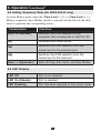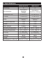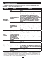
1
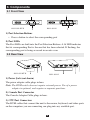
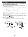
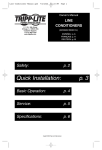
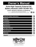
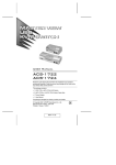
y : a te y
nt n for Li nt
ra tio y ipp rra
ar tra toda E Tr m/wa
W is ne RE co
g nli F e.
Re er o in a ipplit
st w .tr
gi o
re ce t ww
w
an t—
h
c uc
od
r
p
User’s Manual
2- & 4-Port KVM Switches
Model #’s: B022-002-KT-R & B022-004-R
1. Features
2
2. System Requirements
3
3. Components
4
3.1 Front View
4
3.2 Rear View
4
4. Installation
5
5. Operation
6
5.1 Manual Port Selection
6
5.2 Hotkey Port Selection
6
5.3 Auto Scan Mode
7
5.4 Skip Mode (B022-004-R only)
8
5.5 Hotkey Summary Table (for B022-004-R only)
9
5.6 LED Display
9
6. Specifications
10
7. Troubleshooting
11
8. Warranty
12
Español
13
Français
25
Note: F
ollow these installation and operating procedures to ensure correct performance and to
prevent damage to this unit or to its connected devices.
Tripp Lite World Headquarters
1111 W. 35th Street, Chicago, IL 60609 USA
(773) 869-1234, www.tripplite.com
Copyright © 2008 Tripp Lite. All rights reserved. All trademarks are the property of their respective
owners. Technical specifications are subject to change without notice.
1. Features
•
•
•
•
•
•
•
•
•
•
•
•
•
•
•
Compact design
Works with all major operating systems
PS/2 and USB compatible
Easy to install—no software required—simple plug and play operation
Easy to operate—computer selection via push-buttons or Hotkeys
Power on detection—automatically switches to the first powered on port
Auto scan function to monitor computer operation
LED display for easy status monitoring
Hot pluggable—add or remove computers without powering down the
switch
Caps Lock, Num Lock, and Scroll Lock states are saved and restored when
switching
Keyboard and mouse emulation for error-free computer booting
Supports Microsoft® IntelliMouse® and the scrolling wheel on most mice
Superior video quality—up to 2048 x 1536; DDC2B
Self-powered for any location
Saves time, space, power, and equipment costs
2
2. System Requirements
Console
• A VGA, SVGA, or Multisync monitor capable of the highest resolution that
you will be using on any computer in the installation
• A PS/2 style keyboard
• A PS/2 style mouse
Computers
The following equipment must be installed on each computer that is to be
connected to the system:
• A VGA, SVGA, or Multisync port
• A PS/2 or USB keyboard port
• A PS/2 or USB mouse port
Cables
• A Console Connector Cable is provided with this package.
[HD15 (F) and 2 PS/2 (F) connectors]
• P774-series KVM cable kits - PS/2
• P776-series KVM cable kits - USB
• (2) P774-series KVM cable kits are included with the B022-002-KT-R. Use
a B015-000 PS/2 to USB adapter (sold separately) to connect to a USB
computer.
3
3. Components
3.1 Front View
B022-002-KT-R
B022-004-R
1) Port Selection Buttons
• Press a button to select the corresponding port
2) Port LEDs
The Port LEDs are built into the Port Selection Buttons. A lit LED indicates
that its corresponding Port is the one that has been selected. If flashing, the
corresponding port is being accessed in an auto scan.
3.2 Rear View
B022-002-KT-R
B022-004-R
1) Power Jack (not shown)
The power adapter cable plugs in here.
Note: The KVM switch does not require external power. Use of a power
adapter is optional, and requires a separate purchase.
2) Console Port Connector
The Console Adapter Cable plugs in here.
3) CPU Port Connectors
The KVM cables that connect the unit to the mouse, keyboard, and video ports
on the computers you are connecting can plug into any available port.
4
4. Installation
Note: Make sure all PS/2 computers are powered off prior to installation.
1) Refer to the diagrams as you do the following:
2) Plug the Console Adapter Cable into the Console Port Connector on the
rear panel of the KVM switch.
3) Plug your keyboard, monitor and mouse into their respective connectors on
the Console Adapter Cable. The connectors are color-coded and marked
with an appropriate icon for easy identification.
4) Use the Tripp Lite KVM cables (described in the Cables section on p. 3),
to connect the CPU Ports on the KVM switch to the monitor, keyboard
and mouse ports of the computers you are installing.
5) While power is rarely needed, if you choose to use external power, plug a
power adapter into an AC power source, then plug the power adapter cable
into the unit’s Power Jack.
Note: The power adapter should be DC9V with the inside positive and the
outside negative:
6) Turn on the power to the computers.
Note: The KVM’s default is to link to the first computer you turn on.
B022-002-KT-R
B022-004-R
5
5. Operation
5.1 Manual Port Selection
With Manual Port Selection, simply press the appropriate Port Selection button
on the unit’s front panel to select its corresponding port. The Port LED lights
to indicate that its port has been selected.
5.2 Hotkey Port Selection
Hotkey port selection allows you to directly access a computer from the
keyboard, instead of having to manually switch to it with the Port Selection
button.
On the B022-002-KT-R:
1) Press and hold down the [Num Lock] key.
2) Press and release the [Asterisk] key or the [Minus] key.
Note: The [Asterisk] or [Minus] key must be released within one half
second, otherwise Hotkey activation is canceled, and it has no effect.
3) Release the [Num Lock] key.
4) The port will immediately switch.
On the B022-004-R:
1) Press and hold down the [Num Lock] key.
2) Press and release the [Asterisk] key or the [Minus] key.
Note: The [Asterisk] or [Minus] key must be released within one half
second, otherwise Hotkey activation is canceled, and it has no effect.
3) Release the [Num Lock] key.
4) The Caps Lock and Scroll Lock LEDs on the keyboard will flash in
succession. They stop flashing and revert to normal status when you exit
Hotkey Mode. Enter the number for the desired port (1, 2, 3 or 4).
6
5. Operation (continued)
5.3 Auto Scan Mode
The KVM Switch’s Auto Scan feature automatically cycles through the ports
at regular 5 seconds intervals so that you can monitor the computer activity
without having to take the trouble of switching manually.
Note: While Auto Scan Mode is in effect, ordinary keyboard and mouse
functions are suspended. You must exit Auto Scan Mode in order to regain
normal control of their use.
On the B022-002-KT-R:
1) Press and hold down both manual port switches on the front of the KVM
and hold down for 5 seconds. Auto Scan will be initiated.
2) Once scanning begins, it continues until you press one of the manual port
switches on the front of the KVM.
On the B022-004-R:
1) Press and hold down the [Num Lock] key.
2) Press and release the [Asterisk] key or the [Minus] key.
Note: The [Asterisk] or [Minus] key must be released within one half
second, otherwise Hotkey activation is canceled, and it has no effect.
The [Caps Lock] and [Scroll Lock] LEDs on the keyboard will flash in
succession. They stop flashing and revert to normal status when you
exit Hotkey Mode.
3) Release the [Num Lock] key.
4) Press and release [A].
Once scanning begins, it continues until you press [Esc] or [Spacebar]
to exit Auto Scan Mode. The Port that is active at the time scanning
stops remains active.
7
5. Operation (continued)
5.4 Skip Mode (B022-004-R only)
This feature allows you to skip from the currently active Port to the
Previous or Next one with a single keystroke. In contrast to Auto Scan
Mode (which switches Ports at a fixed interval), you can maintain
activation on a particular port for as long or as little as you like.
To activate Skip Mode:
1) Press and hold down the [Num Lock] key.
2) Press and release the [Asterisk] key or the [Minus] key
Note: The [Asterisk] or [Minus] key must be released within one half
second, otherwise Hotkey activation is canceled, and it has no effect.
The Caps Lock and Scroll Lock LEDs on the keyboard will flash in
succession. They stop flashing and revert to normal status when you
exit Hotkey Mode.
3) Release the [Num Lock] key.
4) Press [ ] to skip from the current port to the port that comes before it
(3 to 2; 2 to 1, etc.).
5) Press [ ] to skip from the current port to the port that comes after it (1
to 2; 2 to 3, etc.).
Note: Skip Mode remains in effect until you exit it. You can use [ ]
and [ ] as often as you like. Ordinary keyboard and mouse functions
are suspended— only [ ] and [ ] can be input. You must exit Skip
Mode in order to regain normal control of the console.
6) Pressing [Esc] or [Spacebar] exits both Skip Mode and Hotkey Mode.
8
5. Operation (continued)
5.5 Hotkey Summary Table (for B022-004-R only)
Activate Hotkey mode using the [Num Lock] + [*]; or [Num Lock] + [-]
Hotkey command. Once Hotkey mode is activated, hit the keys in the table
below to perform the corrsponding action.
Combination
Function
[Port ID Number]
Switches the KVM selection to the
computer that corresponds to that Port ID.
[A]
Activates Auto Scan Mode
[ ]
Switches the KVM selection from the
current port to the previous port.
[ ]
Switches the KVM selection from the
current port to the next port.
[Esc] or [Spacebar]
Exits Hot Key, Auto Scan, and Skip Modes.
5.6 LED Display
LED Off
Port is not selected
LED On (Steady)
Port is selected
LED Flashing
Port has been selected in Auto Scan mode
9
6. Specifications
CPU Ports
B022-002-KT-R
B022-004-R
2
4
Port Selection
Push-Button
Switches;
Hotkeys
Push-Button
Switches; Hotkeys
Connectors CPU
2 x HD15 (F)
4 x HD15 (F)
Console
1 x HD15 (F)
1 x HD15 (F)
2 Selected Port
(Green)
4 Selected Port
(Green)
Emulation Keyboard
PS/2
PS/2
Mouse
PS/2
PS/2
LEDs
Scan Interval
5 secs.
5 secs.
Operating Temperature
32° F - 122° F
32° F - 122° F
Storage Temperature
4° F - 140° F
4° F - 140° F
Humidity
0 - 80% RH,
Noncondensing
0 - 80% RH,
Noncondensing
Housing
Metal
Metal
Weight
Dimensions (L x W x H)
0.73 lbs.
1.1 lbs.
4.9 x 3.1 x 1.0 in.
7.9 x 3.1 x 1.0 in.
10
7. Troubleshooting
If you are experiencing problems, first make sure that there are no cable
problems. Check all cable connections.
Problem
Cause
Mouse needs to be
reset
Switch needs to be
reset
Solution
Unplug the mouse from the Switch, then plug it
back in.
Turn off the PCs. Wait 5 seconds; then turn the
PCs on.
The switch will only work with a PS/2 mouse. A
serial mouse cannot be converted to a PS/2
mouse by using a serial to PS/2 adapter. One
Wrong type of mouse exception is a combo-mouse which is specifically
or adapter
designed for both applications. In this case,
Mouse Not
ensure that the mouse is set up for PS/2 mode
Responding*
and is being used with the adapter originally
provided.
Each PC needs to be using the mouse driver
correlating to the mouse connected to the
console port.
Unsupported or
Some newer mice (with extra buttons and wheels)
incorrect mouse
have unique drivers that may not be supported.
driver
Try a regular mouse with a generic mouse driver
(like the one that comes with the operating
system).
Resolution and/or
The Switch supports VGA, SVGA, Multisync,
Bandwidth set too
and XGA (interlaced) monitors with resolutions
high
of up to 2048 x 1536 Hz.
A power source such
Video
as a power panel or
Problems
Move the device that is creating the
poorly insulated
electromagnetic interference, or move the KVM
device is too close
switch and/or its cables.
to the KVM switch or
its cables
Keyboard needs to
Unplug the keyboard from the Switch, then plug
be reset
it back in.
Switch needs to be
Turn off the PCs. Wait 5 seconds; then turn the
reset
PCs on.
Keyboard Not
On 4-port, press the [Spacebar] to exit Auto Scan
Responding* Switch is in Auto Scan mode. On 2-port, press any manual port selection
Mode
awitch on the KVM.
Switched between
Shut down the PC and reboot without switching
PCs during boot-up
between PCs.
procedure
* Some notebook computers, notably the IBM® Thinkpad® and Toshiba® Tecra®, have trouble working with a
switch when their mouse and keyboard ports are used simultaneously. To avoid this problem, only connect
the mouse port or the keyboard port to the switch. If you connect the mouse port, you will need to use the
notebook’s keyboard when the notebook is the active computer. These switches are designed to work with
PS/2 keyboards. Older XT (84 key) and AT keyboards will not work.
11
8. Warranty
FCC Radio / TV Interference Notice
Note: This equipment has been tested and found to comply with the limits for a Class B digital device,
pursuant to Part 15 of the FCC Rules. These limits are designed to provide reasonable protection against
harmful interference in a residential installation. This equipment generates, uses and can radiate radio
frequency energy, and if not installed and used in accordance with the instruction manual, may cause
interference to radio communications. However, there is no guarantee that interference will not occur in a
particular installation. If this equipment does cause harmful interference to radio or television reception,
which can be determined by turning the equipment off and on, the user is encouraged to try to correct the
interference using one or more of the following measures: reorient or relocate the receiving antenna;
increase the separation between the equipment and the receiver; connect the equipment into an outlet on
a circuit different from that which the receiver is connected; consult the dealer or an experienced radio/
television technician for help. The user must use shielded cables and connectors with this product. Any
changes or modifications to this product not expressly approved by the party responsible for compliance
could void the user’s authority to operate the equipment. This device complies with part 15 of the FCC
rules. Operation is subject to the following 2 conditions: (1) This device may not cause harmful
interference, and (2) This device must accept any interference received, including interference that may
cause undesired operation.
5-YEAR LIMITED WARRANTY
Tripp Lite warrants its products to be free from defects in materials and workmanship for a period of five
(5) years from the date of initial purchase. Tripp Lite’s obligation under this warranty is limited to
repairing or replacing (at its sole option) any such defective products. To obtain service under this
warranty, you must obtain a Returned Material Authorization (RMA) number from Tripp Lite or an
authorized Tripp Lite service center. Products must be returned to Tripp Lite or an authorized Tripp Lite
service center with transportation charges prepaid and must be accompanied by a brief description of the
problem encountered and proof of date and place of purchase. This warranty does not apply to
equipment which has been damaged by accident, negligence or misapplication or has been altered or
modified in any way.
EXCEPT AS PROVIDED HEREIN, Tripp Lite MAKES NO WARRANTIES, EXPRESS OR
IMPLIED, INCLUDING WARRANTIES OF MERCHANTABILITY AND FITNESS FOR A
PARTICULAR PURPOSE. Some states do not permit limitation or exclusion of implied warranties;
therefore, the aforesaid limitation(s) or exclusion(s) may not apply to the purchaser.
EXCEPT AS PROVIDED ABOVE, IN NO EVENT WILL Tripp Lite BE LIABLE FOR DIRECT,
INDIRECT, SPECIAL, INCIDENTAL OR CONSEQUENTIAL DAMAGES ARISING OUT OF THE
USE OF THIS PRODUCT, EVEN IF ADVISED OF THE POSSIBILITY OF SUCH DAMAGE.
Specifically, Tripp Lite is not liable for any costs, such as lost profits or revenue, loss of equipment, loss
of use of equipment, loss of software, loss of data, costs of substitutes, claims by third parties, or
otherwise.
Tripp Lite World Headquarters
1111 W. 35th Street, Chicago, IL 60609 USA
(773) 869-1234, www.tripplite.com
English
TRIPP LITE has a policy of continuous improvement. Specifications are subject to change without
notice.
1111 W. 35th Street, Chicago, IL 60609 USA
773.869.1234 (USA) • 773.869.1212 (International)
www.tripplite.com
2009XXXXX 93-2181_EN