1
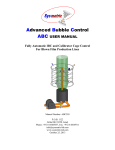
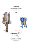
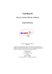
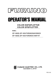
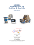
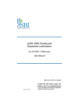
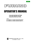
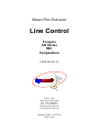
Blown Film Extrusion
Line Control
5 Layers
CD Series
IBC
Temperature
USER MANUAL
P.O.B. 1122
Afula Illit 18550, Israel
Tel: +972-4-6405857
Fax: +972-4-6405911
[email protected]
www.sysmetric-ltd.com
Manual Number: 5CDIT102
January 2010
Line Control – 5 Layers with CD
User Manual
Table of Contents
1.
1.1.
1.2.
1.3.
2.
INTRODUCTION ................................................................................... 3
BLOWN FILM EXTRUSION ........................................................................ 3
LINE CONTROL ........................................................................................ 3
THIS MANUAL ......................................................................................... 4
SYSTEM OVERVIEW............................................................................ 5
2.1.
CONTROL PANEL ..................................................................................... 5
2.2.
CONTROL DISPLAY .................................................................................. 6
2.2.1. Entering Numeric Values ..................................................................... 6
2.3.
CD SERIES GRAVIMETRIC DOSING UNITS................................................. 7
3.
MONITOR AND CONTROL SCREENS............................................... 8
3.1.
LINE SCREEN........................................................................................... 8
3.2.
LINE TEMPERATURE SCREEN ................................................................. 10
3.2.1. Quick Heat ........................................................................................ 10
3.2.2. Extruders and Die Temperature Screens ............................................ 11
3.3.
DOSING SCREEN .................................................................................... 12
3.4.
TOTAL SCREEN...................................................................................... 13
3.5.
LINE SERVICE SCREEN........................................................................... 14
3.5.1. General Screen .................................................................................. 16
3.5.2. IBC Tuning Screen ............................................................................ 18
3.5.3. Model Screen..................................................................................... 19
3.6.
MOTOR STATUS SCREEN........................................................................ 21
3.7.
ALARMS SCREEN ................................................................................... 22
4.
4.1.
4.2.
4.3.
4.4.
4.5.
4.6.
4.7.
PRODUCTION STABILITY AND ACCURACY................................ 23
CD WEIGHING BUCKET LOADCELL ........................................................ 23
CD MIXER INLET PROXIMITY SWITCH ................................................... 23
CD MIXER ROTATION PROXIMITY SWITCH ............................................ 23
ROW MATERIAL SUPPLY........................................................................ 23
BATCH PREPARATION PROCESS TIME ..................................................... 24
BATCH SIZE .......................................................................................... 24
SCREW CAPACITY OUT OF RANGE ......................................................... 24
www.sysmetric-ltd.com
-2-
Line Control – 5 Layers with CD
User Manual
1. Introduction
1.1. Blown Film Extrusion
Blown film extrusion is the process of extruding plastic through a circular die and
blowing the melted plastic into a bubble-like expansion. The bubble is pulled upwards
until it passes through a nip-roll where it is flattened to create what is known as layflat of blown film. At the end of this process the lay-flat is winded on reels.
Extruding the plastic through the die can be done using several extruders in order to
manufacture multi-layer films with each layer being made from different materials
with different properties.
The bubble size, in the blown film extrusion, is dependent on the amount of air
introduced into the bubble and the position of a calibration cage (if exists). The air
inside the bubble can be continuously exchanged by what is known as IBC (Internal
Bubble Cooling) system. Cooling the air inside the bubble helps cooling the plastic
faster and thus enables increasing the production throughput.
Manufacturing film by this process gives the ability to regulate the film’s width and
thickness by controlling the volume of air inside the bubble, the output of the extruder
and the speed of the nip-roll.
1.2. Line Control
Sysmetric’s Line Control systems are designed to control the different sub-systems
involved in the blown film production line in order to manufacture the film with the
desired properties. The different sub-systems and controls are:
• Raw material handling – can be carried out by one of two systems:
ο Graviman – loss-in-weight follow-up on the extruder throughput.
ο CD Series – batch type gravimetric dosing units for preparing defined
mixtures of raw material. The extruder’s throughput is determined and
monitored by the batch preparation rate.
Material handling can also include conveying the raw material to the
Graviman/CD and to the extruder.
• Extruder – controlling the extruder speed (RPM).
• IBC and calibrator cage – controlling the air exchange inside the bubble and
the calibrator position to form the desired width of lay-flat.
• Nip-roll – tuning the nip-roll speed for the desired Meter/Minute.
• Tension and Winder – adjusting the tension rolls and winder speed to tense the
lay-flat and wind it on the reels.
• Temperature – controlling the temperature of the extruder, the die and the
tension rolls.
• Remote control – setting parameters to the production line and data acquisition
from a remote PC (Minuman software).
www.sysmetric-ltd.com
-3-
Line Control – 5 Layers with CD
User Manual
By controlling and monitoring these sub-systems, the Line Control can ensure film
production with specific properties of:
• Width
• Thickness (gram-per-meter)
• Layers Ratio (in multi-layer production lines)
The different models of Sysmetric’s Line Control systems involve different
combinations of the above mentioned sub-systems of the production line and can
control part or all the parameters of the blown film extrusion.
1.3. This Manual
This manual describes Sysmetric’s line control system for blown film production
lines, which involves the following:
• 5 CD Series gravimetric dosing units (the CD model is selected to fit the
production line throughput).
• Control on the speed of the 5 extruders.
• Layers ratio – adjusting the relative speeds of the extruders to receive the
desired layers ratio.
• Thickness – adjusting the extruders speed to receive the desired film’s
thickness.
• Width – control over the calibration cage and the IBC system to produce the
desired lay-flat width (ABC system).
• Temperature – control over the temperature of the extruders and the die.
www.sysmetric-ltd.com
-4-
Line Control – 5 Layers with CD
User Manual
2. System Overview
2.1. Control Panel
IV
CONTROL
VOLTAGE
III
II
OMRON
NS10
I
ALARM
SILENT
0
EXTRUDERS
NIP
NIP ROTATE
AIR RING
BLOWER
IBC
1
1
1
1
1
0
0
0
0
0
OPEN/CLOSE
BUBBLE
CAGE
LINE CONTROL
MANUAL GROUP AUTO
1.
EMERGANCY
STOP
Figure 2.1-1 – Control panel
The control panel of the system consists of the following:
• Control voltage lamp indicates power supply
• Alarm silent push-button for muting the alarm bell
• Extruders on/off switch
• Nip-roll on/off switch and open/close push button
• Nip rotation on/off switch
• Air ring blower on/off switch and speed control potentiometer
• IBC intake blower on/off switch and speed control potentiometer
• Bubble cage open/close and up/down push buttons
• Line control switch to select control mode
• Emergency stop push button
• Auto-pilot stages push buttons 0, I, II, III, IV
• Touch screen display for programming and monitoring
www.sysmetric-ltd.com
-5-
Line Control – 5 Layers with CD
User Manual
2.2. Control Display
Figure 2.2-1 – Control display
The control display is a color touch-screen panel. Every operation on the display is
carried out by pressing gently on the display. Activating a button is carried out by
pressing gently on the display where the button is drawn. Changing numeric values is
carried out by pressing gently on the display where the value is written.
2.2.1. Entering Numeric Values
Several screens (e.g. LINE screen) have one or more editable numeric items (e.g. the
percentage of each layer). To modify the value of an item, carry out the following:
1. Select the item that you want to edit by pressing gently on the display where
that item appears. A pop-up screen with numeric keypad will appear on the
display.
2. Enter the new value using the numeric keypad. If the item has a decimal point,
use the ‘.’ key to move to the fractional part. For example, to enter 12.3, press
‘1’, ‘2’, ‘.’ followed by ‘3’.
3. Press the Enter key to confirm the change. The keypad screen will close and
the item will receive the new value.
Cancel editing by pressing the X button in the keypad screen.
Figure 2.2-2 – Numeric keypad
www.sysmetric-ltd.com
-6-
Line Control – 5 Layers with CD
User Manual
2.3. CD Series Gravimetric Dosing Units
The CD Series gravimetric dosing units are Sysmetric’s solution to raw material
dosing for extrusion and injection molding processes. The CD doser reduces material
cost, utilizing its high accuracy to lower the amount of expensive additives in the
product. The batch weighing nature of the doser offers calibration-free operation and
up-to-the-gram accumulation of raw material flowing through the system. The
mechanical simplicity of the CD series units, and its practical design, ensures easy
maintenance-free operation. The control unit of the CD doser combines automatic
adaptive tuning and noise filtering algorithms with the ruggedness, open architecture,
and extensibility of an industry-standard PLC.
The CD Series dosing units are divided to 5 models for different capacities:
• CD100 for up to 100Kg/h
• CD400 for up to 400Kg/h
• CD800 for up to 800Kg/h
o CD800HD200 for up to 1000Kg/h
o CD800HD400 for up to 1200Kg/h
Note: the stated capacities refer to granulated material with 0.5 Liter/Kg density and
may vary with different materials.
The Line Control operation principles are the same for all CD models and this manual
refers to all models. For detailed information on the CD Series dosing units, operation
and maintenance, please refer to Sysmetric’s CD Series user manual.
www.sysmetric-ltd.com
-7-
Line Control – 5 Layers with CD
User Manual
3. Monitor and Control Screens
3.1. Line Screen
The line screen is the main screen of the system. This screen shows the extruders’
status and the production parameters. Press the LINE button to switch the display to
the line screen.
Figure 3.1-1 – Line screen
The line screen shows the following data:
• For each extruder (Ex A, Ex B, Ex C, Ex D, Ex E):
o SET and ACTUAL output as percentage of the total line throughput
o Kg/hr - The output by Kg/hr
o RPM - The extruder’s RPM
o LOAD - The extruder’s motor LOAD shown in Amps (or in
percentages relatively to the maximum amps of the motor)
o Melt Temperature and Melt Pressure
• Set and actual WEB WIDTH and BUBBLE GAP.
• Set and actual WEB THICKNESS and its calibration Factor.
• Kg/hr and THICKNESS for the Auto-pilot stages I, II, III, IV
• Production parameters:
o Line speed by m/min
o Web’s gram-per-meter by gr/m
o Line’s throughput by Kg/hr
• Scanner On/Off - Web’s thickness scanner control (optional)
www.sysmetric-ltd.com
-8-
Line Control – 5 Layers with CD
User Manual
Control buttons on the line screen when the line control is in manual mode:
• Ex # Start/Stop – start and stop the extruder
• Ex # +/- – increase and decrease the extruder’s speed
Control buttons on the line screen when the line control is in group mode:
• Output +/- – increase and decrease the line’s output
Control buttons on the line screen when the line control is in automatic mode:
• Speed +/- – increase and decrease the line’s speed (nip-roll speed)
www.sysmetric-ltd.com
-9-
Line Control – 5 Layers with CD
User Manual
3.2. Line Temperature Screen
The line temperature screen is used for setting and monitoring the desired and the
actual temperatures of the extruders, the die, the IBC air and the cooling air ring.
Press the LINE °C button to switch the display to the temperature screen.
Figure 3.2-1 – Line temperature screen
3.2.1. Quick Heat
The buttons on the right side of the temperature screen enable quick adjustment of the
temperatures. Pressing these buttons will set all the temperatures to the preset value
(the preset values are determined in the General line service screen). Pressing the
OFF button will turn off all of the heaters. Pressing the Profile button will set each
zone to its working temperature.
www.sysmetric-ltd.com
- 10 -
Line Control – 5 Layers with CD
User Manual
3.2.2. Extruders and Die Temperature Screens
The extruders and the die temperature screens show extra data on the heaters.
SV – the set temperature
PV – the actual temperature
Eff – the working ratio of the heater
Amps – the current that is driven to the heater
A.Amps – the maximum allowed current. A higher current will cause the system to
alarm.
Figure 3.2-2 – Extruder temperature screen
Figure 3.2-3 – Die temperature screen
www.sysmetric-ltd.com
- 11 -
Line Control – 5 Layers with CD
3.3.
User Manual
Dosing Screen
The dosing screen shows the set dosing formula for each extruder and the actual
formula according to the last batch that the system prepared. To enter this screen,
press the DOSING button on the control panel.
Figure 3.3-1 – Dosing screen
To set the dosing formula press the Extruder # label to open the formula screen, enter
the desired dosing formula for the specific extruder, ensure that the Total is 100.0%
and press Replace Formula to activate the new formula.
Figure 3.3-2 – Extruder formula screen
See the CD Series user manual for more details on the dosing formula.
www.sysmetric-ltd.com
- 12 -
Line Control – 5 Layers with CD
User Manual
3.4. Total Screen
The total screen shows the amount of raw material that was dispensed at each channel
of each dosing unit for each extruder. To enter this screen, press the Total button on
the control panel.
Figure 3.4-1 – Total screen
Press the RESET button to reset the accumulators.
www.sysmetric-ltd.com
- 13 -
Line Control – 5 Layers with CD
User Manual
3.5. Line Service Screen
The line service screen is used for setting and monitoring parameters of the line’s
speed and selecting speed calibration mode. Press the LINE SERVICE button on the
control display to switch to the line service screen. The system will request the access
password. The password is 4321.
Figure 3.5-1 – Line service screen
Set Speed Data
1. Ramp rate – defines the time in seconds for ramping the production throughput
from 0 to 100%.
2. Length pulse distance – the circumference in millimeters of the roll where the
digital speed proximity switch is installed.
3. Length pulse per Rev – the number of pulses that the digital speed proximity
switch generates per one revolution of the roll where it is installed.
4. Automatic start speed – the minimum start speed of the nip-roll. This value is used
by the control to start the nip-roll when the production is in automatic mode.
Actual Speed Data
1. Maximum speed – is the calculated maximum line speed. This value is calculated
based on the speed calibration.
2. Analog speed – the current line speed according to the analog input.
3. Digital speed – is the calculated line speed according to the digital pulses. This
value is averaged over 30 seconds and thus it is accurate only when the line speed
has not been changed for at least 30 seconds.
4. S.d. speed – the standard deviation of the line speed in percentage units. This
value is calculated when the line is in automatic calibration.
www.sysmetric-ltd.com
- 14 -
Line Control – 5 Layers with CD
User Manual
Auto Calibration
The control system uses the analog speed for calculating the extruders speed in order
to maintain the desired film’s Kg/M. The analog speed, calculated from the nip-roll’s
motor driver reference voltage, tends to vary with time and does not maintain
stability. When the system is set to automatic calibration mode it uses the digital
speed sensor to continuously calibrate the analog speed thus maintaining the correct
extruder speed and correct Kg/M.
To enable automatic mode press the AUTO CALIBRATE push button in the control
display. The label next to the push button will display ON to indicate automatic mode.
Pressing the button again will disable the automatic mode.
Speed Calibration
1. Auto Cal. Range – defines the allowed range of automatic calibration.
2. Manual Calibrate – manually calibrating the line speed. This calibration can only
be carried out when the automatic calibration is disabled. There are two ways to
manually calibrate the line speed:
a. Measure the actual line speed with a measuring device and enter that value
in the Manual Calibrate field.
b. Copy the Digital speed value to the Manual Calibrate value.
www.sysmetric-ltd.com
- 15 -
Line Control – 5 Layers with CD
User Manual
3.5.1. General Screen
The general screen holds general parameters of the line operation. To enter this screen
press the LINE SRVICE button on the control display and then press General.
Figure 3.5-2 – General screen
Hour Counters
1. Extruder # – the total working hours of each extruder.
2. Line – the total working hours of the line.
3. Vacuum Pump – the total working hours of the vacuum pump.
Oscillating Table
Oscillating Table Rotation Time – defines the time to complete one rotation of the
oscillating table.
Temperature
1. Temperature Range +/- – range of temperature around the set temperature that is
considered normal. When the extruder’s actual temperature exceeds this range the
system will indicate a too low temperature by a blue color on the temperature
label or too high by a red color on the temperature label.
2. Minimum Extruder Temperature – the minimum temperature for activating the
extruder.
3. Minimum Extruder Soak Time – the minimum time that the extruder is at the
Minimum Extruder Temperature (or higher temperature) before allowing
activating the extruder.
4. Minimum Die Temperature – the minimum temperature for activating the die.
5. Minimum Die Soak Time – the minimum time that the die is at the Minimum Die
Temperature (or higher temperature) before allowing activating the line.
6. Maximum Cabinet Extruder Temp – the temperature to alarm on high temperature
at the cabinet of the extruder’s motor drivers.
www.sysmetric-ltd.com
- 16 -
Line Control – 5 Layers with CD
User Manual
7. Temp Profile # – define the temperatures for the quick heat in the temperature
screen.
Extruders
1. Extruder # Max RPM – the maximum RPM of each extruder.
2. Extruder Pressure Alarm – the pressure at which the system will alarm.
3. Extruder Pressure Stop – the pressure at which the system will stop the extruder.
www.sysmetric-ltd.com
- 17 -
Line Control – 5 Layers with CD
User Manual
3.5.2. IBC Tuning Screen
The IBC tuning screen holds parameters for the IBC control. To enter this screen
press the LINE SERVICE button on the control display and then press IBC Control.
Figure 3.5-3 – IBC Tuning screen
See the ABC user manual for details on the IBC parameters.
www.sysmetric-ltd.com
- 18 -
Line Control – 5 Layers with CD
User Manual
3.5.3. Model Screen
The system uses a control technique called “modeling”. The modeling technique is a
special control technique that enables stable and accurate control. It is based on the
actual terms involved in the process, as opposed to the general control techniques
(PID etc.). The idea of the modeling technique is to evaluate the mass per revolution
that the extruder screw pumps. The model evaluation is capable of handling the screw
nonlinearity as well. All calculations are carried out in natural controller numbers
rather than physical terms in order to obtain full accuracy (for this reason some of the
values will use “z” units). To enter the model screen, press the LINE SPEED button
on the control display and then press MODEL.
Figure 3.5-4 – Model screen
Monitor
1. RPM – the R.P.M. of the extruder in percentage.
2. Output – the output of the extruder in Kg/h.
3. Reject – minimum time delay between adjacent batches. If a second batch is
processed before this time has elapsed the system will temporarily disable the
control and will preset the batch Counter to 4u.
4. Counter – batch counter that represents the system stability. The system is
considered stable when the counter is at zero.
5. Last cap – the last estimated extruder’s capacity in gram per revolution. It is
calculated in relative units, denoted by z. The Last cap is compared to the min and
max levels, after every batch, and if exceeds the Counter is preset to 4u. Such an
event occurs usually after interference in the material flow and it stops the values
updating until the line stabilizes again.
6. Average cap – the final filtered value of the extruder’s capacity.
7. S.D. – the standard deviation of the screw capacity values in percentage units.
www.sysmetric-ltd.com
- 19 -
Line Control – 5 Layers with CD
User Manual
Setup
1. Max cap – the maximum allowed value for the Last cap parameter.
2. Min cap – the minimum allowed value for the Last cap parameter.
3. Reject Set – the set value for the Reject timer.
www.sysmetric-ltd.com
- 20 -
Line Control – 5 Layers with CD
User Manual
3.6. Motor Status Screen
The motor status screen shows the line’s motor drivers alarms. The screen shows
active alarms if exists and recent alarms (memory alarms). Press the Motor Status
button on the control display to switch to this screen.
Figure 3.6-1 – Motor Status screen
www.sysmetric-ltd.com
- 21 -
Line Control – 5 Layers with CD
User Manual
3.7. Alarms Screen
The system creates an alarm log. Press the ALARM button on the display to switch to
the alarm log screen.
Figure 3.7-1 – Alarms screen
The alarm log shows which alarms were active and the start and end time of each
alarm.
www.sysmetric-ltd.com
- 22 -
Line Control – 5 Layers with CD
User Manual
4. Production Stability and Accuracy
The control on the extruder throughput relies on the known size batches of raw
material supplied to the extruder continuously by the CD dosing unit. During
operation, every time a batch of raw material is supplied to the extruder the Last cap
is updated. In normal operation, the Last cap parameter should be stable, it should be
approximately twice the Min cap value and approximately half the Max cap value and
it should be close to the Average cap value. In addition, the S.D. should be lower than
4%. Monitoring these values for several consecutive batches will provide all the data
necessary to locate any problem.
If the Last cap value is not stable and/or the S.D. is relatively high (more than 4%)
check the following:
4.1. CD Weighing Bucket Loadcell
1. Clean the weighing bucket loadcell of the CD dosing unit.
2. Check if the loadcell is connected tightly to the housing.
3. Check if the weighing bucket is calibrated. See Calibration chapter in CD Series
user manual for more details.
4.2. CD Mixer Inlet Proximity Switch
1. Stop the CD dosing unit.
2. Open the weighing bucket service door on the CD mixer chamber and check that
the proximity switch is free of dirt.
3. Define the type of proximity switch installed in the system by checking its color
and act accordingly.
• For orange Proximity Switch:
i. Turn the sensitivity screw located at the back of the proximity
switch clockwise until the indicator LED turns off.
ii. Turn the sensitivity screw counterclockwise slowly until the
indicator LED turns on.
iii. Turn the screw counterclockwise half a turn more.
• For yellow Proximity Switch:
i. Turn the sensitivity screw located at the back of the proximity
switch clockwise until the indicator LED turns on.
ii. Turn the sensitivity screw counterclockwise slowly until the
indicator LED turns off.
iii. Turn the screw counterclockwise one more turn.
4.3. CD Mixer Rotation Proximity Switch
Monitor the CD mixer rotation proximity switch to verify it works properly:
1. While the production line and the CD unit are on, verify that when the mixer
rotates the sensor’s indication light is blinking.
2. Verify that the mixer is constantly stopping at the same angle.
4.4. Raw Material Supply
Check if the raw material supply to the CD unit is ok. There should always be
material in the hopper loaders of the CD when batches are prepared, otherwise the
batch preparation process can become too long and the supply continuity can be
www.sysmetric-ltd.com
- 23 -
Line Control – 5 Layers with CD
User Manual
damaged. However, one raw material supply problem in 10 minutes is still acceptable
and will not disturb the stability and the accuracy.
4.5. Batch Preparation Process Time
Batch preparation process in the CD unit should always be shorter than 1 minute. If
the process is longer than 1 minute monitor the CD unit and identify the cause of
delay.
4.6. Batch Size
If the batch size of the CD unit is too small it causes the batches to be supplied, from
the dosing unit to the extruder, in pairs and that can disturb the control process. When
it happens the interruption counter (Counter) of the system is preset to the value 4u,
standard deviation (S.D.) will be relatively high (more than 4%) and the gram per
revolution value (Last cap) will be instable.
4.7. Screw Capacity Out of Range
If the value of Last cap is out of range or close to the minimum or maximum levels
please consult Sysmetric support.
www.sysmetric-ltd.com
- 24 -