1
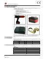
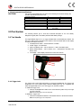
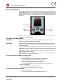
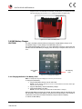
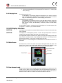
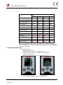
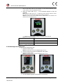
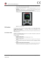
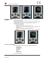
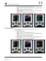
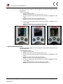
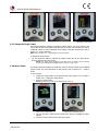
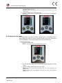
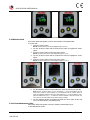
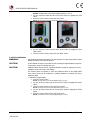
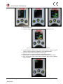
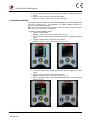
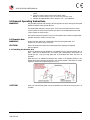
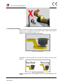
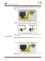
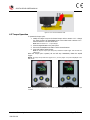
DIGITAL B-RAD USER MANUAL
TABLE OF CONTENTS
TABLE OF CONTENTS ....................................................................... 1
MANUAL REVISION HISTORY ......................................................... 2
IMPORTANT SAFETY NOTICE .......................................................... 3
1.0 General Information .................................................................. 5
1.1 System Components ................................................................... 5
1.2 Specifications ............................................................................. 5
1.2.1 Torque Ranges............................................................................ 5
1.2.2 Battery Specifications ................................................................... 5
1.2.3 Environmental Specifications......................................................... 6
2.0 Tool System ............................................................................... 6
2.1 Tool Handle ............................................................................... 6
2.1.1 Trigger Lock ............................................................................... 6
2.2 Screen Navigation ....................................................................... 7
2.3 RAD Li-Ion Battery Pack .............................................................. 7
2.3.1 Insert/Remove the RAD Li-Ion Battery Pack ................................... 7
2.3.2 Checking RAD Battery Charge ....................................................... 7
2.4 RAD Battery Charger................................................................... 8
2.4.1 Charging the RAD Li-Ion Battery Pack ............................................ 8
2.4.2 Charging Errors ........................................................................... 9
3.0 LCD Display Interface ................................................................ 9
3.1 Main Screen ............................................................................... 9
3.2 User Access Levels...................................................................... 9
3.2.1 Unlocking Access Levels .............................................................. 10
3.2.2 Returning to the Locked Level ...................................................... 11
3.3 Functions ................................................................................. 12
3.3.1 Select a Preset ........................................................................... 12
3.3.2 Hard Joint Mode ......................................................................... 13
3.3.3 View Tool Information................................................................. 13
3.3.4 View Last Result ......................................................................... 14
3.3.5 View Life Cycles ......................................................................... 15
3.3.6 View Maintenance Cycles............................................................. 15
3.3.7 Change the Target Torque........................................................... 16
3.3.8 Save a Preset ............................................................................. 16
3.3.9 Change the Torque Units............................................................. 17
3.3.10 Set the Clock............................................................................ 18
3.3.11 Clear Maintenance Cycles .......................................................... 18
3.3.12 Tool Calibration ........................................................................ 19
3.3.13 Default Calibration .................................................................... 21
4.0 General Operating Instructions .............................................. 22
4.1 Reaction Arm ........................................................................... 22
4.1.1
4.1.2
4.1.3
4.1.4
Installing the Reaction Arm.......................................................... 22
Reaction Arm Height ................................................................... 23
Reaction Arm Foot ...................................................................... 24
Reaction Points .......................................................................... 24
4.2 Torque Operation ..................................................................... 25
5.0 Errors ....................................................................................... 26
6.0 Contact Us ................................................................................ 27
New World Technologies Inc.
V2015.01.28
Page • 1
DIGITAL B-RAD USER MANUAL
MANUAL REVISION HISTORY
Revision 2014.07.03: Initial Manual Release
Revision 2014.12.17:
New World Technologies Inc.
V2015.01.28
-
Updated Hardware – Handle
-
DBRAD22.0312 Firmware Release
Page • 2
DIGITAL B-RAD USER MANUAL
IMPORTANT SAFETY NOTICE
RAD TOOLS ARE SAFE AND RELIABLE. NOT FOLLOWING PRECUATIONS
AND INSTRUCTIONS OUTLINED HERE CAN RESULT IN INJURY TO THE
TOOL, OPERATOR AND FELLOW WORKERS.
NEW WORLD TECHNOLOGIES INCORPRATED IS NOT RESPONSIBLE FOR
ANY SUCH INJURY.
Digital B-RAD Tool System Safety
The intended use of the Digital B-RAD Tool System is for commercial and
industrial bolting applications.
Do not operate the Digital B-RAD Tool System before reading and understanding
this user manual and noting the Safety Notices displayed on the Digital B-RAD
Tool System and throughout this manual.
Only qualified personnel with training in the safe operation of torque tooling and
the Digital B-RAD Tool System should attempt the installation, operation and
diagnosis of the Digital B-RAD Tool System.
The Digital B-RAD Tool System is connected to high voltage power and consists of
external rotating parts. Improper training and use can cause serious or fatal
injury.
Do not disassemble or attempt to repair the Digital B-RAD Tool System; doing so
will void warranty. If breakdown, malfunction or damage occurs and the Digital BRAD Tool System fails to operate correctly, contact New World Technologies Inc.
Technical Support (refer to Section 6.0 – Contact Us).
The Digital B-RAD Tool System should only be used if environmental storage and
operation specifications have been met. Refer to Section 1.2.3 – Environmental
Specifications.
Do not operate the Digital B-RAD Tool System in explosive atmospheres, including,
but not limited to, the presence of flammable liquids, gases or dust. The Digital BRAD Tool System creates sparks which could ignite these substances.
Do not expose the Digital B-RAD Tool System to wet conditions. Water in the
Digital B-RAD Tool System will cause damage to the tool and increase the risk of
electric shock.
After long durations of use, the Digital B-RAD Tool System will become hot. It is
recommended to use the tool in short intervals and allow for cooling between uses
to prevent injury to the operator or damage to the Digital B-RAD Tool System.
While operating the Digital B-RAD Tool System, always wear safety goggles and
keep all body parts clear of moving parts and the reaction arm contact point.
Never exceed the Maximum Torque of the Digital B-RAD Tool System. Failure to
comply will result in void warranty.
The Digital B-RAD Tool System has been calibrated by a qualified Calibration Technician; calibration must be
done by a qualified Calibration Technician. Improper calibration can cause damage to the tool and joint.
New World Technologies Inc.
V2015.01.28
Page • 3
DIGITAL B-RAD USER MANUAL
RAD Li-Ion Battery Pack Safety
Only use the RAD Li-Ion Battery Pack with the Digital B-RAD Tool System. The use
of other batteries with the Digital B-RAD Tool System will cause damage to the
tool.
The RAD Li-Ion Battery Pack should only be charged on the RAD Battery Charger.
If an incompatible charger is used, damage to the RAD Battery will occur.
Keep the RAD Li-Ion Battery Pack away from any metal objects. If the battery
terminals are connected by a metal object, the battery will short and will cause
damage to the battery and injury to the operator.
Do not expose the RAD Li-Ion Battery Pack to wet conditions. This will cause
damage to the RAD Battery and increase the risk of electric shock.
Do not use faulty or deformed RAD Batteries. Do not attempt to open the RAD
Battery. Do not short circuit the RAD Battery. Failure to comply will cause damage
to the RAD Battery and injury to the operator.
If liquid is ejected from the RAD Battery, avoid contact. If contact occurs,
immediately flush with water. If contact with eyes occurs, immediately flush with
water and seek medical aid. Liquid from the RAD Battery may cause irritation
and/or burns.
RAD Li-Ion Battery Packs cannot be disposed of with regular waste. Return RAD
Batteries to your RAD Distributor.
New World Technologies Inc.
V2015.01.28
Page • 4
DIGITAL B-RAD USER MANUAL
1.0 General Information
1.1 System Components
The Digital B-RAD Tool System is shipped from New World Technologies Inc. in a
case with the following parts:
-
Digital B-RAD Tool (Figure 1.1-1)
Two RAD Li-Ion Battery Packs (Figure 1.1-2)
RAD Battery Charger (Figure 1.1-3)
Standard Reaction Arm and Snap Ring (Figure 1.1-4)
Calibration Certificate
User Manual
Figure 1.1-1: Digital B-RAD Tool
Figure 1.1-2: RAD Li-Ion Battery Pack
Figure 1.1-3: RAD Battery Charger
Figure 1.1-4: Standard Reaction Arm
Note: Some distributors may ship additional parts along with the Digital B-RAD Tool System.
1.2 Specifications
1.2.1 Torque Ranges
The following table outlines the torque ranges, in Foot-Pounds and Newton-Meters, of each
Digital B-RAD Tool System:
Imperial
DB-RAD 500
100-500 FtLb
DB-RAD 1000
250-1000 FtLb
DB-RAD 1500
375-1500 FtLb
Table 1.2.1: Torque Ranges
Metric
or
or
or
DB-RAD 675
DB-RAD 1350
DB-RAD 2000
135-675 Nm
340-1350 Nm
510-2000 Nm
1.2.2 Battery Specifications
Ensure that all Battery Specifications are followed when utilizing the Digital B-RAD Tool
System.
Battery Output
Voltage
Current
18 VDC
30 A
60 minutes
Input
Output
115 VAC / 230 VAC
12 – 18 VDC
2.5 A
Charge Time
Charger Voltage
Charger Output Current
New World Technologies Inc.
V2015.01.28
Page • 5
DIGITAL B-RAD USER MANUAL
Table 1.2.2: Battery Specifications
1.2.3 Environmental Specifications
CAUTION!
Only operate the Digital B-RAD Tool System if the following environmental storage and
operation specifications have been met.
Temperature Ranges
Operating Temperature
Charging Temperature
Storage Temperature
Humidity
Shock
Vibration
Required Operating Conditions
̊C
̊F
0 – 35
32 – 95
0 – 50
32 – 122
-25 – 70
-13 – 158
10% to 90% non-condensing
10G according to DIN IEC 68-2-6/29
1G, 10-150Hz according to DIN IEC 68-2-6/29
Non explosive atmosphere
Dry location
Table 1.2.3: Environmental Specifications
2.0 Tool System
2.1 Tool Handle
The following sections give a visual and functional description of the Tool Handle,
Navigation Keypad, RAD Li-Ion Battery Pack and RAD Battery Charger.
The Digital B-RAD (Figure 2.1-1) is trigger activated with a Forward/Reverse Switch. The
RAD Li-Ion Battery Pack is attached to the bottom of the Tool Handle and the LCD Display
is located on the back of the Tool.
1.
2.
3.
4.
5.
Forward/Reverse Switch – controls direction of rotation
On/Off Trigger – tool activation
RAD Li-Ion Battery Pack – refer to Section 2.3 – RAD Li-Ion Battery Pack
Battery Release Button – refer to Section 2.3.1 – Insert/Remove the RAD Li-Ion
Battery Pack
LCD Display – status display with access to menus and controls
5
1
2
4
3
Figure 2.1-1: Digital B-RAD
2.1.1 Trigger Lock
The Trigger Lock is useful while transporting or storing the Digital B-RAD. The Trigger Lock
disables the use of the On/Off Trigger, therefore disabling the tool. It is suggested that
while the Digital B-RAD is not in use, the Trigger Lock should be enabled.
To enable the Trigger Lock:
1. Slide the Forward/Reverse Switch to the Centre Position (neither fully to the right
nor fully to the left).
Note: The On/Off Trigger cannot be depressed.
To disable the Trigger Lock:
1. Slide the Forward/Reverse Switch to the Forward Position or the Reverse Position.
Note: The On/Off Trigger can be depressed.
New World Technologies Inc.
V2015.01.28
Page • 6
DIGITAL B-RAD USER MANUAL
2.2 Screen Navigation
The keypad located below the LCD Display consists of three buttons used to navigate the
Digital B-RAD Interface. The “Up Arrow” button is used to increment through values and
navigate through columns. The “Down Arrow” button is used to decrement through values
and navigate through rows. The “Centre” button is used to select options and enter the
Main Menu.
“Centre” Button
“Down Arrow”
Button
“Up Arrow”
Button
Figure 2.2-1: LCD Display Keypad
Note: When pressing the navigation buttons, press and hold for about a second. This will ensure that
the button press was properly registered.
2.3 RAD Li-Ion Battery Pack
CAUTION!
Only use the RAD Li-Ion Battery Pack with the Digital B-RAD Tool System. Using other
batteries may damage the Digital B-RAD Tool System.
CAUTION!
Keep the RAD Li-Ion Battery Pack away from any metal objects. If the battery terminals are
connected by a metal object, the battery will short and cause damage to the battery and
injury to the operator.
The RAD Li-Ion Battery Pack supplies power to the tool and the LCD Display. For the
Digital B-RAD to preform best, ensure the RAD Battery is fully charged and in good
condition before use. In optimal conditions, the RAD Battery should be capable of
approximately 100 Torque Cycles at 50% of the Maximum Torque on a joint with a
hardness of approximately 10 degrees.
Note: The application torque, joint hardness, battery condition, age and operating temperature will
affect the actual number of Torque Cycles per charge.
2.3.1 Insert/Remove the RAD Li-Ion Battery Pack
To insert the RAD Battery:
1. Ensure the On/Off Trigger is in the Off Position (not depressed).
2. Align the RAD Battery with the bottom of the Tool Handle.
3. Slide the RAD Battery into place until it is full seated.
Note: A click will confirm that the RAD Battery is locked in place.
4.
Test that the RAD Battery is locked in place by trying to slide it out of place.
To remove the RAD Battery:
1. Press and hold the Battery Release Button.
2. Slide the RAD Battery away from the Tool Handle.
2.3.2 Checking RAD Battery Charge
To check the RAD Battery Charge:
1. Press the “Charge” button on the RAD Battery (Figure 2.3.2-1).
New World Technologies Inc.
V2015.01.28
Page • 7
DIGITAL B-RAD USER MANUAL
Result: The Red Bars will light up. If all of the Red Bars are illuminated, the Battery is fully
charged. If none of the Red Bars are illuminated, the RAD Battery is completely discharged
and needs charging (refer to Section 2.4.1 – Charging the RAD Li-Ion Battery Pack).
“Charge” Button
Figure 2.3.2-1: RAD Li-Ion Battery Pack
2.4 RAD Battery Charger
CAUTION!
The RAD Li-Ion Battery Pack should only be charged on the RAD Battery Charger. If an
incompatible charger is used, damage to the RAD Battery will occur.
The Charging Status Display (Figure 2.4-1) on the RAD Battery Charger is used to notify the
operator when the RAD Battery is charging, when the charge is complete and if there is an
error.
Green Status
Light
Red Warning
Light
Figure 2.4-1: Charging Status Display
2.4.1 Charging the RAD Li-Ion Battery Pack
Note: The temperature range for charging is 0˚C to 50˚C (32 ̊ F to 122 ̊ F).
To charge the RAD Battery:
1. Plug the RAD Battery Charger into the wall outlet.
Result: The Red Warning Light will turn on for one second and then the Green Status Light
will turn on for one second.
2.
3.
Align the RAD Battery with the RAD Battery Charger.
Slide the RAD Battery into place.
Result: The Green Status Light will flash while the RAD Battery is charging.
When the RAD Battery has been fully charged, the Green Status Light will stop flashing and
stay illuminated. Until the RAD Battery is removed from the RAD Charger, it will convert to
conservation mode which will maintain the battery charge at maximum capacity.
To remove the RAD Battery:
New World Technologies Inc.
V2015.01.28
Page • 8
DIGITAL B-RAD USER MANUAL
1.
2.
2.4.2 Charging Errors
Slide the RAD Battery away from the RAD Charger.
Check that the RAD Battery is fully charged (refer to Section 2.3.2 – Checking RAD
Battery Charge).
The Red Warning Light is on:
The RAD Battery is not charging because its temperature is not within the required
range for charging. When the RAD Battery’s temperature moves within the required
range, the Red Warning Light will turn off and charging will commence.
The Red Warning Light is flashing:
The RAD Battery may be placed incorrectly on the RAD Battery Charger. Remove the
RAD Battery and replace it correctly on the RAD Battery Charger. If the Red Warning
Light continues to flash, the RAD Battery is defective; remove the RAD Battery
immediately.
If these problems continue, contact New World Technologies Inc. Technical Support (refer
to Section 6.0 – Contact Us) or your RAD Distributor.
3.0 LCD Display Interface
CAUTION!
LCD Displays are susceptible to mechanical shock and any force exerted on the module may
result in damage.
CAUTION!
LCD Displays can be damaged by moisture or water and high temperatures. Avoid such
conditions when storing and gently wipe clean or let dry before usage.
The Digital B-RAD Controller includes an LCD Display. This simple LCD Display interface has
many functions, including Presets, Torque Settings and Calibration. The following sections
describe these functions, as well as how to enable and/or use them.
Refer to Section 2.2 – Screen Navigation to understand the use of the buttons referred to in
this section.
3.1 Main Screen
The Main Screen is used as the central control point of the Digital B-RAD Tool System. The
Target Torque, Torque Units, Digital B-RAD Model and Tool Status are displayed on the
Main Screen. Figure 3.1-1 shows the main screen and indicates important aspects.
Digital B-RAD Model
Tool Status
Target Torque
Torque Units
Figure 3.1-1: Main Screen
3.2 User Access Levels
Access to the functions on the LCD Display has been constricted to four Access Levels: the
Locked Level, the Basic Level, the Intermediate Level and the Advanced Level. Access to
the last three levels requires a password. Each level has a different password and access to
different functions. Table 3.2-1 outlines the functions accessible to each level.
New World Technologies Inc.
V2015.01.28
Page • 9
DIGITAL B-RAD USER MANUAL
Level
Functions
Locked
Basic
Intermediate
Advanced
Selecting a Preset
YES
YES
YES
YES
Hard Joint Mode
YES
YES
YES
YES
View Tool Information
YES
YES
YES
YES
View Last Result
YES
YES
YES
YES
View Life Cycles
YES
YES
YES
YES
View Maintenance Cycles
YES
YES
YES
YES
Change Target Torque
NO
YES
YES
YES
Save a Preset
NO
YES
YES
YES
Change Torque Units
NO
YES
YES
YES
Set the Clock
NO
NO
NO
YES
Clear Maintenance Cycles
NO
NO
NO
YES
Tool Calibration
NO
NO
NO
YES
Default Calibration
NO
NO
NO
YES
Table 3.2-1: User Access Levels and Functions
Note: The Digital B-RAD Tool System is shipped from factory in the Basic Level. After configuration, it
is recommended that the tool be locked for normal bolting operations to avoid inadvertent changes to
tool settings and calibration.
3.2.1 Unlocking Access Levels
To unlock an Access Level:
1. Press the “Centre” button.
Result: The Main Menu screen will be displayed (Figure 3.2.1-1).
2.
3.
Press the “Down Arrow” button to highlight the “Unlock” option.
Press the “Centre” button.
Result: The Password Input screen will be displayed (Figure 3.2.1-2).
Figure 3.2.1-1: Main Menu Screen
4.
New World Technologies Inc.
V2015.01.28
Figure 3.2.1-2: Password Input Screen
Use the navigation keypad to enter the desired password.
Page • 10
DIGITAL B-RAD USER MANUAL
Note: Use the “Up Arrow” button to move horizontally (⟷) across the Password Keyboard.
Use the “Down Arrow” button to move vertically (↕) on the Password Keyboard. Use the
“Centre” button to select the highlighted character.
5.
Select the “Check Mark” key (√ ) on the Password Keyboard to enter the
password.
Note: Select the “Back Arrow” key (⟵) to delete the previous character. Select the “Cancel”
key (∅) to return to the Main Menu screen without entering a password.
Result: The Main screen will be displayed and the Digital B-RAD is now unlocked to the
desired Access Level (Figure 3.2.1-3).
Figure 3.2.1-3: Main Screen in the Basic, Intermediate or Advanced Level
Note: The Lock Icon is not visible.
Access Level
Passcode
Basic
37232
Intermediate
Contact your RAD Distributer
Advanced
Contact your RAD Distributer
Table 3.2.1-1: Access Levels and Passwords
3.2.2 Returning to the Locked Level
To return to the Locked Access Level:
1. Press the “Centre” button.
Result: The Main Menu screen will be displayed (Figure 3.2.2-1).
2.
3.
Press the “Down Arrow” button to highlight the “Lock” option.
Press the “Centre” button.
Result: The Password Input screen will be displayed (Figure 3.2.2-2).
Figure 3.2.2-1: Main Menu Screen
4.
New World Technologies Inc.
V2015.01.28
Figure 3.2.2-2: Password Input Screen
Use the navigation keypad to enter the Basic Level Password.
Page • 11
DIGITAL B-RAD USER MANUAL
Note: Use the “Up Arrow” button to move horizontally (⟷) across the Password Keyboard.
Use the “Down Arrow” button to move vertically (↕) on the Password Keyboard. Use the
“Centre” button to select the highlighted character.
5.
Select the “Check Mark” key (√ ) on the Password Keyboard to enter the
password.
Note: Select the “Back Arrow” key (⟵) to delete the previous character. Select the “Cancel”
key (∅) to return to the Main Menu screen without entering a password.
Result: The Main screen will be displayed and the Digital B-RAD will be in the Locked Access
Level (Figure 3.2.2-3).
Figure 3.2.2-3: Main Screen in Locked Level
Note: The Lock Icon is visible.
3.3 Functions
The following sections describe the functions available on the Digital B-RAD Display
Interface. Refer to Section 3.2 – User Access Levels for more information on the
accessibility of these functions.
Note: Menus will look different depending on the access level. The figures in this section are from the
Advanced Access Level.
3.3.1 Select a Preset
A Preset is a pre-defined Target Torque value. They allow the operator to quickly and
efficiently change the Target Torque.
To select a Preset:
1. Press the “Centre” button.
Result: The Main Menu screen will be displayed (Figure 3.3.1-1).
2.
Press the “Centre” button.
Result: The highlight will move to the list of Presets on the right side of the screen (Figure
3.3.1-1).
3.
4.
Use the “Up Arrow” button and the “Down Arrow” button to highlight the desired
Preset.
Press the “Centre” button to select the Preset.
Result: The LCD Display will return to the Main screen. The Target Torque will be the Preset
Torque and the Preset number will be displayed at the top of the screen (Figure 3.3.1-3).
New World Technologies Inc.
V2015.01.28
Page • 12
DIGITAL B-RAD USER MANUAL
Figure 3.3.1-1: Main Menu Screen
Figure 3.3.1-2: Presets Menu Screen
Figure 3.3.1-3: Main Screen
3.3.2 Hard Joint Mode
CAUTION!
Damage to the Digital B-RAD and the joint may occur if the Joint Rate is less than 10 ̊ and
Hard Joint Mode is not enabled.
The Digital B-RAD is calibrated for a Joint Rate greater than 10 ̊. The Hard Joint Mode
allows the Digital B-RAD to operate on a joint with a Joint Rate of less than 10 ̊.
To enable/disable Hard Joint Mode:
1. Press the “Centre” button.
Result: The Main Menu screen will be displayed (Figure 3.3.2-1).
2.
3.
Use the “Up Arrow” button and the “Down Arrow” button to highlight the “Hard
Joint” option.
Press the “Centre” button to select the “Hard Joint” option.
Result: The LCD Display will return to the Main screen with Hard Joint displayed (Figure
3.3.2-2).
Figure 3.3.2-1: Main Menu Screen
Figure 3.3.2-2: Main Screen – Hard Joint Mode
3.3.3 View Tool Information
This function allows the operator to view the Digital B-RAD information including:
Date and Time
Software Version
Digital B-RAD Model
Serial Number
Current Units
Voltage
Minimum Torque
Maximum Torque
To view the Tool Information:
New World Technologies Inc.
V2015.01.28
Page • 13
DIGITAL B-RAD USER MANUAL
1.
Press the “Centre” button.
Result: The Main Menu screen will be displayed (Figure 3.3.3-1).
2.
3.
Use the “Up Arrow” button and the “Down Arrow” button to highlight the “Info”
option.
Press the “Centre” button to select the “Info” option.
Result: The Info Menu screen will be displayed (Figure 3.3.3-2). The “Tool Info” option will
already be highlighted.
4.
Press the “Centre” button to select the “Tool Info” option.
Result: The Tool Information screen will be displayed (Figure 3.3.3-3).
Figure 3.3.3-1: Main Menu Screen
3.3.4 View Last Result
Figure 3.3.3-2: Info Menu Screen
Figure 3.3.3-3: Tool Info Screen
This function allows the operator to view the result of the last Torque Cycle.
To view the Last Result:
1. Press the “Centre” button.
Result: The Main Menu screen will be displayed (Figure 3.3.4-1).
2.
3.
Use the “Up Arrow” button and the “Down Arrow” button to highlight the “Info”
option.
Press the “Centre” button to select the “Info” option.
Result: The Info Menu screen will be displayed (Figure 3.3.4-2).
4.
5.
Use the “Up Arrow” button and the “Down Arrow” button to highlight the “Last
Result” option.
Press the “Centre” button to select the “Last Result” option.
Result: The Last Result screen will be displayed (Figure 3.3.4-3).
Figure 3.3.4-1: Main Menu Screen
New World Technologies Inc.
V2015.01.28
Figure 3.3.4-2: Info Menu Screen
Figure 3.3.4-3: Example of Last Result
Screen
Page • 14
DIGITAL B-RAD USER MANUAL
3.3.5 View Life Cycles
This function allows the operator to view the statistics of all the Cycles conducted over the
life of the tool.
To view the Life Cycles:
1. Press the “Centre” button.
Result: The Main Menu screen will be displayed (Figure 3.3.5-1).
2.
3.
Use the “Up Arrow” button and the “Down Arrow” button to highlight the “Info”
option.
Press the “Centre” button to select the “Info” option.
Result: The Info Menu screen will be displayed (Figure 3.3.5-2).
4.
5.
Use the “Up Arrow” button and the “Down Arrow” button to highlight the “Life
Cycles” option.
Press the “Centre” button to select the “Life Cycles” option.
Result: The Life Cycles screen will be displayed (Figure 3.3.5-3).
Figure 3.3.5-1: Main Menu Screen
Figure 3.3.5-2: Info Menu Screen
3.3.6 View Maintenance Cycles
Figure 3.3.5-3: Example of Life Cycles
Screen
This function allows the operator to view the statistics of all the Cycles conducted since the
tool’s last maintenance.
To view Maintenance Cycles:
1. Press the “Centre” button.
Result: The Main Menu screen will be displayed (Figure 3.3.6-1).
2.
3.
Use the “Up Arrow” button and the “Down Arrow” button to highlight the “Info”
option.
Press the “Centre” button to select the “Info” option.
Result: The Info Menu screen will be displayed (Figure 3.3.6-2).
4.
5.
Use the “Up Arrow” button and the “Down Arrow” button to highlight the “Maint
Cycles” option.
Press the “Centre” button to select the “Maint Cycles” option.
Result: The Maintenance Cycles screen will be displayed (Figure 3.3.6-3).
New World Technologies Inc.
V2015.01.28
Page • 15
DIGITAL B-RAD USER MANUAL
Figure 3.3.6-1: Main Menu Screen
Figure 3.3.6-2: Info Menu Screen
3.3.7 Change the Target Torque
Figure 3.3.6-3: Example of
Maintenance Cycles Screen
This function allows the operator to change the Target Torque. The Target Torque is the
torque value at which the Digital B-RAD will stop the Torque Cycle and the cycle will be
considered a pass. For more information on the Target Torque and Torque Cycle, refer to
Section 4.2 – Torque Operation.
Note: Refer to Section 1.2.1 – Torque Ranges for more information.
1.
To change the Target Torque:
Use the “Up Arrow” button to increase the Target Torque and use the “Down Arrow”
button to decrease the Target Torque.
Result: The Target Torque displayed on the Main screen will change. Once the desired
Target Torque is displayed, the Digital B-RAD is ready for a Torque Cycle.
3.3.8 Save a Preset
This function allows the operator to modify any of the ten Presets. Presets are pre-defined
Target Torques. For more information on using Presets, refer to Section 3.3.1 – Select a
Preset.
To save a Preset:
1. Change the Target Torque to the desired torque value (Figure 3.3.8-1). Refer to
Section 3.3.7 – Change the Target Torque.
2. Press the “Centre” button.
Result: The Main Menu screen will be displayed (Figure 3.3.8-2).
Figure 3.3.8-1: Main Screen
3.
4.
New World Technologies Inc.
V2015.01.28
Figure 3.3.8-2: Main Menu Screen
Use the “Up Arrow” button and the “Down Arrow” button to highlight the “Save”
options.
Press the “Centre” button to select the “Save” option.
Page • 16
DIGITAL B-RAD USER MANUAL
5.
Use the “Up Arrow” button and the “Down Arrow” button to highlight the Preset to
be modified (Figure 3.3.8-3).
Note: The Target Torque previously saved as this Preset will be overwritten by the new
Target Torque.
6.
Press the “Centre” button to select the Preset.
Result: The Target Torque is now saved as the Preset and is displayed in the Presets Menu
(Figure 3.3.8-4).
Figure 3.3.8-3: Presets Menu
Figure 3.3.8-4: Presets Menu
3.3.9 Change the Torque Units
This function allows the operator to change the torque units to Foot-Pounds (FtLb) or
Newton-Meters (Nm). When the units are changed, the Target Torque value, Preset Torque
Values and Calibration Values are automatically converted to the selected units.
To change the torque units:
1. Press the “Centre” button.
Result: The Main Menu screen will be displayed (Figure 3.3.9-1).
Figure 3.3.9-1: Main Menu Screen
2.
3.
Use the “Up Arrow” button and the “Down Arrow” button to highlight the “Units”
option.
Press the “Centre” button to select the “Units” option.
Result: If the units were FtLb, they will change to Nm. If the units were Nm, they will
change to FtLb.
Result: The Main screen will be displayed. Confirm that the correct units are displayed
(Figure 3.3.9-2).
New World Technologies Inc.
V2015.01.28
Page • 17
DIGITAL B-RAD USER MANUAL
Figure 3.3.9-2: Different Units Displayed on the Main Screen
3.3.10 Set the Clock
This function allows the operator to set the time and date on the Digital B-RAD.
To set the clock:
1. Press the “Centre” button.
Result: The Main Menu screen will be displayed (Figure 3.3.10-1).
2.
3.
Use the “Up Arrow” button and the “Down Arrow” button to highlight the “Setup”
option.
Press the “Centre” button to select the “Setup” option.
Result: The Setup Menu screen will be displayed (Figure 3.3.10-2).
4.
5.
Use the “Up Arrow” button and the “Down Arrow” button to highlight the “Clock”
option.
Press the “Centre” button to select the “Clock” option.
Result: The Clock Setting screen will be displayed (Figure 3.3.10-3).
Figure 3.3.10-1: Main Menu Screen
6.
Figure 3.3.10-2: Setup Menu Screen
Figure 3.3.10-3: Clock Setting Screen
Use the navigation buttons and the keyboard to select and edit the time and date.
Note: Use the “Up Arrow” button to move horizontally (⟷) across the keyboard. Use the
“Down Arrow” button to move vertically (↕) on the keyboard. Use the “Centre” button to
select the highlighted character. Select the “Check Mark” key (√ ) on the keyboard to enter.
Select the “Back Arrow” key (⟵) to delete the previous character. Select the “Cancel” key
(∅) to return to the Clock Setting screen without making a change.
7.
Use the navigation buttons to highlight and select the “Save” option to save and
exit or the “Exit” option to exit without saving.
3.3.11 Clear Maintenance Cycles
This function allows the operator to clear the statistics in Maintenance Cycles.
To clear Maintenance Cycles:
New World Technologies Inc.
V2015.01.28
Page • 18
DIGITAL B-RAD USER MANUAL
1.
2.
3.
Press the “Centre” button.
Result: The Main Menu screen will be displayed (Figure 3.3.11-1).
Use the “Up Arrow” button and the “Down Arrow” button to highlight the “Info”
option.
Press the “Centre” button to select the “Info” option.
Result: The Info Menu screen will be displayed (Figure 3.3.11-2).
Figure 3.3.11-1: Main Menu Screen
4.
5.
Figure 3.3.11-2: Info Menu Screen
Use the “Up Arrow” button and the “Down Arrow” button to highlight the “Zero
Maint” option.
Press the “Centre” button to select the “Zero Maint” option.
3.3.12 Tool Calibration
WARNING!
Only qualified personnel with training in the safe operation of torque tooling and the Digital
B-RAD Tool System should operate this tool.
CAUTION!
Do not calibrate at Target Torques that result in exceeding the Digital B-RAD Tool System’s
Torque Range. Severe tool damage will occur.
CAUTION!
Calibration should only be done by a Qualified Calibration Technician. Improper use of the
calibration function will result in tool damage.
This function allows the operator to access the calibration values for the Digital B-RAD.
These values should only be modified by a Qualified Calibration Technician and using a
Calibration Stand.
To calibrate the Digital B-RAD:
1. Press the “Centre” button.
Result: The Main Menu screen will be displayed (Figure 3.3.12-1).
2.
3.
Use the “Up Arrow” button and the “Down Arrow” button to highlight the “Setup”
option.
Press the “Centre” button to select the “Setup” option.
Result: The Setup Menu screen will be displayed (Figure 3.3.12-2).
4.
5.
Use the “Up Arrow” button and the “Down Arrow” button to highlight the “Calib”
option.
Press the “Centre” button to select the “Calib” option.
Result: The Calibration screen will be displayed (Figure 3.3.12-3).
New World Technologies Inc.
V2015.01.28
Page • 19
DIGITAL B-RAD USER MANUAL
Figure 3.3.12-1: Main Menu Screen
6.
7.
Figure 3.3.12-2: Setup Menu Screen
Figure 3.3.12-3: Calibration Screen
Do one Torque Cycle.
Press the “Centre” button to highlight the Actual Torque (Figure 3.3.12-4).
Figure 3.3.12-4: Calibration Screen – Actual Torque Highlighted
8.
Use the “Up Arrow” button and the “Down Arrow” button to change the Actual
Torque to the value given by the transducer on the Calibration Stand.
9. Press the “Centre” button to deselect the Actual Torque.
10. Press the “Up Arrow” button to display the next Calibration screen.
11. Repeat steps 6 – 10 until a Torque Cycle has been conducted at 18% to 100%.
12. Press and hold the “Centre” button until the Calibration Menu screen is displayed
(Figure 3.3.12-5).
New World Technologies Inc.
V2015.01.28
Page • 20
DIGITAL B-RAD USER MANUAL
Figure 3.3.12-5: Calibration Menu Screen
13. Use the “Up Arrow” button and the “Down Arrow” button to highlight the “Save”
option.
14. Press the “Centre” button to select the “Save” option.
Note: To exit calibration without saving, select the “Exit” option.
3.3.13 Default Calibration
This function allows the operator to use the Default Calibration Values while calibrating the
tool (refer to Section 3.3.12 – Tool Calibration). The Default Calibration Values are a
reference point for efficient calibration.
Note: These values should never be used as Calibration Values. After enabling the Default Calibration
Values, the operator must calibrate the Digital B-RAD.
To enable the Default Calibration Values:
1. Press the “Centre” button.
Result: The Main Menu screen will be displayed (Figure 3.3.13-1).
2.
3.
Use the “Up Arrow” button and the “Down Arrow” button to highlight the “Setup”
option.
Press the “Centre” button to select the “Setup” option.
Result: The Setup Menu screen will be displayed (Figure 3.3.13-2).
Figure 3.3.13-1: Main Menu Screen
4.
5.
Figure 3.3.13-2: Setup Menu Screen
Use the “Up Arrow” button and the “Down Arrow” button to highlight the “Calib”
option.
Press the “Centre” button to select the “Calib” option.
Result: The Calibration screen will be displayed (Figure 3.3.13-3).
6.
Press and hold the “Centre” button until the Calibration Menu screen is displayed
(Figure 3.3.13-4).
Figure 3.3.13-3: Calibration Screen
New World Technologies Inc.
V2015.01.28
Figure 3.3.13-4: Calibration Menu Screen
Page • 21
DIGITAL B-RAD USER MANUAL
7.
8.
Use the “Up Arrow” button and the “Down Arrow” button to highlight the “Default”
option.
Press the “Centre” button to select the “Default” option.
Result: The Default Calibration Values are saved as the Calibration Values.
9.
Calibrate the Digital B-RAD. Refer to Section 3.3.12 – Tool Calibration.
4.0 General Operating Instructions
WARNING!
Only qualified personnel with training in the safe operation of torque tooling and the Digital
B-RAD Tool System should operate this tool.
The Digital B-RAD operates in Torque Cycles. The Torque Cycle passes when the Actual
Torque reaches the Target Torque and the Cycle fails if it is interrupted before the Actual
Torque reaches the Target Torque.
This section instructs the operator in the use of the Reaction Arm needed for Digital B-RAD
operation and how to conduct a Torque Cycle.
4.1 Reaction Arm
WARNING!
Always keep body parts clear of the Reaction Arm when the Digital B-RAD Tool
System is in use. Serious injury could occur.
CAUTION!
Ensure the Reaction Arm has a solid contact point before operating the Digital B
RAD Tool System.
4.1.1 Installing the Reaction Arm
Ensure the Reaction Arm and Snap Ring are installed securely to hold the Reaction Arm in
place. Make sure the Reaction Arm is in contact with a solid Reaction Point before you
operate the tool. Keep your body parts clear of the Reaction Arm when the tool is in
operation.
When the tool is in operation the Reaction Arm rotates in the opposite direction to the
Output Square Drive and must be allowed to rest squarely against a solid object or surface
adjacent to the bolt to be tightened (Figure 4.1.1-1).
Figure 4.1.1-1 – Reaction Arm Rotation
CAUTION!
Keep your hand and body parts clear of the Reaction Arm and barrel when the tool is in
operation.
New World Technologies Inc.
V2015.01.28
Page • 22
DIGITAL B-RAD USER MANUAL
Figure 4.1.1-2: Incorrect Placement of Hand/Body Parts During Operation
4.1.2 Reaction Arm Height
Ensure the height of the socket is even with the height of the Reaction Arm as seen below
in Figure 4.1.2-1. The height of the socket cannot be shorter or higher than the height of
the Reaction Arm as seen below in Figure 4.1.2-2.
CORRECT: The Reaction Arm and socket are even height.
Figure 4.1.2-1: Correct Height
INCORRECT: The leg of the Reaction Arm is too short on the left side, and too long on the
right side.
Figure 4.1.2-2: Incorrect Height
IMPROPER REACTION WILL VOID WARRANTY AND CAN CAUSE PREMATURE TOOL
FAILURE.
New World Technologies Inc.
V2015.01.28
Page • 23
DIGITAL B-RAD USER MANUAL
4.1.3 Reaction Arm Foot
Ensure the foot of the Reaction Arm aligns with the length of the nut as seen in Figure
4.1.3-1. The length of the foot cannot be shorter or longer than the nut as seen in Figure
4.1.3-2.
CORRECT: The foot of the Reaction Arm aligns with the length of the nut.
Figure 4.1.3-1: Correct Length
INCORRECT: The foot of the Reaction Arm is too short on the left side, and too long on
the right side.
Figure 4.1.3-2: Incorrect Length
Please contact New World Technologies Inc or your local RAD Authorized Distributor for
custom Reaction Arms.
4.1.4 Reaction Points
Ensure the Reaction Arm reacts off the middle of the foot as seen in Figure 4.1.4-1. Do not
react off the heel of the reaction foot as seen in Figure 4.1.4-2.
CORRECT: Reaction Arm is reacting off the middle of the Reaction Arm’s foot.
Figure 4.1.4-1: Correct Reaction Point
INCORRECT: Reaction Arm is reacting off the heel of the Reaction Arm. This can cause
premature tool failure.
New World Technologies Inc.
V2015.01.28
Page • 24
DIGITAL B-RAD USER MANUAL
Figure 4.1.4-2: Incorrect Reaction Point
4.2 Torque Operation
To operate the Torque Cycle:
1. Modify the Target Torque to the desired torque. Refer to Section 3.3.7 – Change
the Target Torque if the Digital B-Rad is not in the Locked Level or Section 3.3.1 –
Select a Preset if it is in the Locked Level.
Note: Refer to Section 1.2.1 – Torque Ranges.
2.
3.
4.
Place the Digital B-RAD on the joint system.
Ensure the Forward/Reverse Switch is in the Forward Position.
Press and hold the On/Off Trigger.
Note: To stop the Torque Cycle at any time, release the On/Off Trigger. This will result in a
Failed Cycle.
When the Torque Cycle is passed, the tool will stop. Immediately release the On/Off
Trigger.
Result: The Target Torque and “Pass” (Figure 4.2-1) or “Fail” (Figure 4.2-2) will be displayed on the
Main screen.
Figure 4.2-1: Passed Torque Cycle
Figure 4.2-2: Failed Torque Cycle
Note: The result will be displayed for ten seconds or until the Digital B-RAD is reversed or a new cycle
is started.
New World Technologies Inc.
V2015.01.28
Page • 25
DIGITAL B-RAD USER MANUAL
5.0 Errors
Important!
Disassembling or attempting repair will void warranty.
In case of an error, the following messages may appear:
STALL
– High torque at start up
HI CURR
– High current during wind-up
NO CURR
– No current during wind-up
LO BATT
– Low battery voltage during wind-up
Solution:
1. Ensure RAD Li-Ion Battery Pack is fully charged. If not, charge the RAD Battery
and re-try. If fully charged, continue with solution.
2. Contact New World Technologies Inc. Technical Support (refer to Section 6.0 –
Contact Us) or your RAD Distributor.
New World Technologies Inc.
V2015.01.28
Page • 26
DIGITAL B-RAD USER MANUAL
6.0 Contact Us
New World Technologies Inc.
30580 Progressive Way
Abbotsford, BC, V2T 6Z2
Canada
Toll Free: 1-800-983-0044
Fax: 604-852-0269
Email: [email protected]
Web: www.radtorque.com
New World Technologies Inc. Technical Support: 1-800-983-0044
(Ext. 227)
Email: [email protected]
New World Technologies Inc.
V2015.01.28
Page • 27