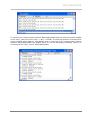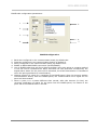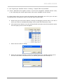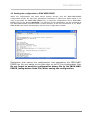
1
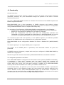
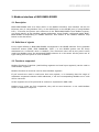
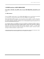
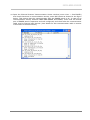
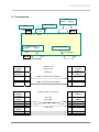
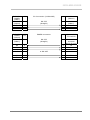
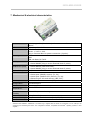
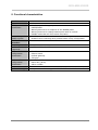
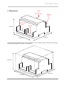
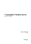
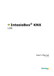
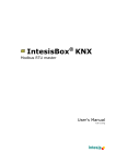
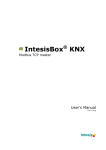
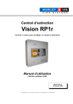
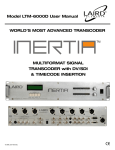
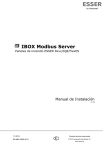
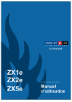
User Manual IBOX-MBS-ESSER Gateway for the integration of ESSER 8007 / 8008 / IQ8 fire panels in Modbus enabled monitoring and control systems. Technical changes reserved May 2012 ES-MN-18001-01-2 IBOX-MBS-ESSER 2 ES-MN-18001-01-2 / May-2012 IBOX-MBS-ESSER INDEX Description .................................................................................................... 4 1.1 Introduction................................................................................................... 4 1.2 Functionality .................................................................................................. 5 1.3 Capacity of IBOX-MBS-ESSER .......................................................................... 6 2. Modbus interface of IBOX-MBS-ESSER............................................................... 7 2.1 Description .................................................................................................... 7 2.2 Definition of signals ........................................................................................ 7 2.3 Functions supported........................................................................................ 7 3. ESSER interface of IBOX-MBS-ESSER ................................................................ 8 3.1 Main features ................................................................................................. 8 4. LinkBoxMB. Configuration & monitoring tool for IBOX-MBS-ESSER Modbus Server series ........................................................................................................... 9 4.1 Introduction .................................................................................................... 9 4.2 Project definition............................................................................................ 10 4.3 Connections configuration ............................................................................... 14 4.4 Signals ......................................................................................................... 16 4.5 Sending the configuration to IBOX-MBS-ESSER .................................................. 18 4.6 Signals viewer ............................................................................................... 19 4.7 System commands ......................................................................................... 20 4.8 Files ............................................................................................................. 21 5. Set-up process and troubleshooting ................................................................ 22 Pre-requisites ..................................................................................................... 22 Set-up procedure ................................................................................................ 22 6. Connections................................................................................................. 25 7. Mechanical & electrical characteristics.............................................................. 27 8. Functional characteristics............................................................................... 28 9. Dimensions.................................................................................................. 29 1. 3 ES-MN-18001-01-2 / May-2012 IBOX-MBS-ESSER 1. Description 1.1 Introduction Integration of ESSER 8007/8008/IQ8 fire panels into a Modbus master device or system, using Box Modbus Server - ESSER gateway. The aim of this integration is to make available points states of ESSER 8007/8008/IQ8 fire panels from a Modbus master device or system. For this IBOX-MBS-ESSER gateway works, from the Modbus system point of view, acting as a Modbus slave device responding to data polls coming from the Modbus master, and from the ESSER system point of view, acting as a serial device connected to its serial port, and serving the data received from ESSER to the Modbus side. IBOX-MBS-ESSER connects to the serial port of the ESSER panel, either through the RS232 port or the RS485 port, software selectable. LAN Master Modbus TCP WAN INTERNET Modbus TCP Master Modbus RTU Ethernet Modbus RTU RS232/RS485 RS232/RS485 ESSER Fire Panel IBOX-MBS- LinkBoxMB configuration software RS232 Only needed for configuration Integration of ESSER 8007/8008/IQ8 fire panels using IBOX-MBS-ESSER 4 ES-MN-18001-01-2 / May-2012 IBOX-MBS-ESSER 1.2 Functionality General overview: The ESSER communication protocol is based on events, the states of the system elements (detectors, modules, etc.) are transmitted through the protocol in the form of events whenever they occur. The role of IBOX-MBS-ESSER consists in associate the elements of the ESSER system with Modbus register addresses. IBOX-MBS-ESSER has a fixed association of ESSER elements with Modbus register addresses. The Modbus value to represent each state of the panel or element is configurable using LinkBoxMB software tool in a simple and friendly way. The procedure of configuration of IBOX-MBS-ESSER consists basically in the following: - Introduction of the communication parameters for Modbus side and for ESSER side. - Assign the values desired in Modbus for each state to integrate. - Once this configuration has been done with the configuration software tool LinkBoxMB, you have to download this configuration to IBOX-MBS-ESSER via a serial connection and IBOX-MBS-ESSER will reboot with the new configuration working. The numerical values that will represent, in the Modbus registers, the different possible states of the ESSER points can be selected in the configuration process. IBOX-MBS-ESSER can be configured as Modbus TCP slave or Modbus RTU (RS232/RS485) slave. The whole capacity of one single ESSER panel is supported. The control of the ESSER panel is permitted, and commands toward the panel are permitted. All ESSER elements (detectors, outputs and zones) are configured in IBOX-MBS-ESSER by default for a single panel. Also all the general events are detected by IBOX-MBS-ESSER and translated to Modbus: The integration operation is as follow: Once IBOX-MBS-ESSER is configured and connected to both systems (ESSER and Modbus), it maintains a "keep alive" message with the panel, being this message the request/response of panel status, also it listens continuously the ESSER serial port for new events. With every event, the new status received is updated in the IBOX-MBS-ESSER memory and become available to be read by the Modbus master device. As mentioned before, the protocol in the serial port of the ESSER is based in spontaneous messages, that is, only changes of status are sent through the protocol whenever they occurs. Because of this, when IBOX-MBS-ESSER starts up, actual status of elements is unknown, but the panel will inform to IBOX-MBS-ESSER about the actual state of the panel and elements when it receives the message requesting the status. 5 ES-MN-18001-01-2 / May-2012 IBOX-MBS-ESSER 1.3 Capacity of IBOX-MBS-ESSER Element Max.* Notes Panel states number 3 General states of the panel in independent Modbus registers. Number of Points 3000 Modbus registers * These maximum values can be extended on demand Ref.: IBOX-MBS-ESSER 6 ES-MN-18001-01-2 / May-2012 IBOX-MBS-ESSER 2. Modbus interface of IBOX-MBS-ESSER 2.1 Description IBOX-MBS-ESSER acts as a slave device in its Modbus interface, this interface can be the Ethernet port (if using Modbus TCP), or the RS232 port or the RS485 port (if using Modbus RTU). To access the points and resources of the IBOX-MBS-ESSER from Modbus system, you must specify as the Modbus register addresses, those fixedly configured inside IBOXMBS-ESSER corresponding to ESSER elements. See details of the Modbus address map below in this document. 2.2 Definition of signals Every signal defined in IBOX-MBS-ESSER corresponds to an ESSER element. Every possible element's status (FIRE, FIRE DISABLED, TEST…) in the ESSER system can be freely associated to a numerical value in Modbus. This numerical value will be the point’s value read from Modbus when the associated ESSER element is in this state. All the points are of type analog from the point of view of Modbus. 2.3 Functions supported Modbus functions 03 and 04 (read holding registers and read input registers) can be used to read Modbus registers. Modbus function 06 must be used to write Modbus registers. If poll records are used to read more than one register, it is necessary that the range of addresses requested contains valid addresses, if not the corresponding Modbus error code will be returned. All the registers are of 2 bytes and its content is expressed in MSB..LSB. Modbus error codes are fully supported, they will be sent whenever a non valid Modbus action or address is required. 7 ES-MN-18001-01-2 / May-2012 IBOX-MBS-ESSER 3. ESSER interface of IBOX-MBS-ESSER This section describes the ESSER part of the IBOX-MBS-ESSER configuration and functionality. This section assumes the user is familiar with ESSER technology and technical terms. 3.1 Main features From the ESSER system point of view, IBOX-MBS-ESSER acts as a serial device connected to its serial port, and serving the data received from ESSER to the Modbus side. IBOX-MBS-ESSER ESSER interface use IDT protocol through RS485 or RS232 connection (TTY board required). The ESSER communication protocol is based on events, the states of the system elements (detectors, modules, etc.) are transmitted through the protocol in the form of events whenever they occur. The 3 general states of the ESSER fire panel are available as independent Modbus registers. Each Modbus register corresponds to a single element of the panel: detector, output or zone. The value offered per each Modbus register reflects the state of the element associated in the panel, the possible values are from 0-Normal, 1-Alarm… to 7-TEST. Each element to detect is defined in a table indicating zone number, output or detector number, and type of element (detector, output or zone). Commands toward the panel are allowed for reset, disconnect and test the elements. When a communication error with the panel occurs it is indicate in the panel. 8 ES-MN-18001-01-2 / May-2012 IBOX-MBS-ESSER 4. LinkBoxMB. Configuration & monitoring tool for IBOX-MBS-ESSER Modbus Server series 4.1 Introduction LinkBoxMB is a Windows® compatible software developed specifically to monitor and configure IBOX-MBS-ESSER Modbus Server series. It is possible to configure all external protocols available for IBOX-MBS-ESSER Modbus Server and to maintain different customer’s configurations based on a LinkBoxMB project for every different installation. Maintaining always on hard disk a copy of the last configuration files for every external protocol and customer, that is to say for every project. From LinkBoxMB, as well as configure the integration signals list and connection parameters for every external protocol, it is permitted to select the serial port to use to connect to IBOX-MBS-ESSER Modbus Server and the use of some tools for monitoring and debugging de device. Some of these tools will be explained in this document but only some of them, the rest of available debugging tools and commands will not be explained here because they are for exclusive use under the recommendations of our technical support. LinkBoxMB allows configuring all IBOX-MBS-ESSER Modbus Server series independently of the external system used. For every external system, LinkBoxMB has a specific configuration window. Periodically, new free versions of LinkBoxMB are released incorporating the latest developed integrations for external systems. 9 ES-MN-18001-01-2 / May-2012 IBOX-MBS-ESSER 4.2 Project definition The first step to do in LinkBoxMB for a new installation is to create the installation’s project giving a descriptive name to it. When you create a project, a new folder is created with the name of the project containing the configuration files needed depending on the external protocol selected for the project. It is strongly recommended that you create a new project for every installation, if not, overwriting of configuration files of previous installations using the same external protocol may occur, loosing the configuration data for those previous installations. The projects folder is located in AppFolder\ProjectsMB, where AppFolder is the installation folder of LinkBoxMB (by default C:\Program Files\Intesis\LinkBoxMB). Inside the projects folder, a new folder will be created for every project defined in LinkBoxMB with the files needed for the project. When you open LinkBoxMB, the project selection window will appear inviting you to select a project or create a new one. A demo project for every external protocol supported is provided with the standard installation of LinkBoxMB. You can create a new project or select a demo project based on the external protocol desired, and create a new one from the demo one selected. Project selection window To create a new project, select a project using the same external protocol you want to use in the new project and click on New button. You will be prompted to create a copy of the selected project (useful for similar installations) or create a brand new one. 10 ES-MN-18001-01-2 / May-2012 IBOX-MBS-ESSER If you select Yes you will be prompted to specify a name and a description for the new project that will be based on the same external protocol than the selected one. If you select No you can specify a name, a description and an external protocol to use from the list of available external protocols. On Accept, a new folder will be created inside the projects folder with the name given to the project, this folder will contain the template configuration files if the project is a brand new one, or a copy of the configuration files if it is a copy of a selected one. A description of the files created for an ESSER protocol based project can be found in section Files in this document. From all the possibilities of LinkBoxMB, only changes in configuration for the integration and configuration file generation can be performed while disconnected from IBOX-MBS-ESSER (working off-line), allowing you to do these tasks in the office more comfortably. Before any monitoring or downloading action to IBOX-MBS-ESSER can be performed, the connection between IBOX-MBS-ESSER and the PC running LinkBoxMB must be established (working online). To do so follow these steps: 1. Make sure IBOX-MBS-ESSER is powered-up a correctly connected to the Modbus system via the Ethernet connection (Modbus TCP) or serial connection (Modbus RTU) and to ESSER panel via the RS232 connection (consult details for connection and pin assignments in section Connections of this document). 2. Connect a free PC serial port to the IBOX-MBS-ESSER serial port marked as PC Console. (Use the standard serial cable supplied with the device or a customer’s cable following the pin assignments specified in section Connections in this document). 11 ES-MN-18001-01-2 / May-2012 IBOX-MBS-ESSER 3. Select in LinkBoxMB the PC serial port used for the connection to IBOX-MBS-ESSER. Use menu Configuration -> Connection. 4. Check the checkbox off-line under the menu bar (it will change automatically to on-line) and LinkBoxMB will ask for INFO about the IBOX-MBS-ESSER connected to it via the serial connection, if the connection is ok then IBOX-MBS-ESSER will respond with its identification (this can be monitored in the IBOX-MBS-ESSER Communication Console window, as showed below). Once connected to IBOX-MBS-ESSER, all the options of LinkBoxMB are fully operative. To monitor the communication between IBOX-MBS-ESSER and the Modbus master device, select the menu View -> Bus -> Modbus. The Modbus communication Viewer window will be opened. This window show in real time all the communication frames between IBOX-MBSESSER and the Modbus master device as well as debugging messages referent to internal protocol (Modbus) sent by IBOX-MBS-ESSER. 12 ES-MN-18001-01-2 / May-2012 IBOX-MBS-ESSER To monitor the communication between IBOX-MBS-ESSER and the external system (ESSER in this case), select the menu View -> Bus -> ESSER. The External protocol communication viewer window will be opened. This window show in real time all the communication frames between IBOX-MBS-ESSER and ESSER panel as well as debugging messages referent to external protocol (IDT) sent by IBOX-MBS-ESSER. 13 ES-MN-18001-01-2 / May-2012 IBOX-MBS-ESSER 4.3 Connections configuration To configure the IBOX-MBS-ESSER connection parameters and the Modbus values for each possible state, select menu Configuration -> IBOX-MBS-ESSER. The ESSER Configuration window will be opened. Select the Connection tab to configure the connection parameters. Two kinds of information are configured using this window, the referent to the Modbus side and the referent to the ESSER side. Modbus side configuration parameters: 2 3 1 4 5 6 7 8 9 Modbus Interface Configuration 1. Select the type of connection desired (TCP or RTU). If Modbus TCP is selected, then: 2. Enter the IP address for IBOX-MBS-ESSER. 3. Enter the IP netmask for IBOX-MBS-ESSER. 4. Enter the default router address to use by IBOX-MBS-ESSER, leave blank if there is no need of router address. 5. Enter the TCP port to use, by default 502. If Modbus RTU is selected, then: 6. 7. 8. 9. 14 Select the type of port to use (RS232 or RS485). Select the baud rate to use. Select the parity (none, even or odd). Enter the Modbus slave number for IBOX-MBS-ESSER. ES-MN-18001-01-2 / May-2012 IBOX-MBS-ESSER ESSER side configuration parameters: 1 5 2 3 6 7 4 ESSER Configuration 1. 2. 3. 4. 5. Baud rate configured in the communication board, by default 600. Data bits configured in the communication board, by default 8. Parity configured in the communication board, by default none. ESSER to IBOX-MBS-ESSER connection (RS232/RS485). List of ESSER codes that will force alarm activation (any point going to a status marked in this list will be considered as alarm activation for the point and consequently the digital alarm status for the point will be activated, the alarm deactivation is considered when the point goes back to normal status). 6. Waiting timeout (8..120s) for a response of the ESSER panel. After this timeout without communication activity from the ESSER panel, the communication error signal for the panel will be activated. 7. When a point is in a status different than normal, after this timeout (8..120s) not receiving notification of status for the point from the ESSER panel, the status of the point will be considered back to normal. 15 ES-MN-18001-01-2 / May-2012 IBOX-MBS-ESSER 4.4 Signals Select the Points tab for a description of the IBOX-MBS-ESSER datapoints. 1 2 3 4 5 6 7 8 9 10 Points list This window is just for information purposes about the datapoints existing into the IBOXMBS-ESSER and its functionality. 1. #. Signal’s number (edit not permitted). Every line in the grid corresponds to a signal (group of ESSER points). Signals (lines in the grid) can be added or deleted selecting the desired line and clicking Add or Delete buttons. Special signals (see below) are fixed (deletion not permitted). This column is used only to enumerate the lines in the grid (signals). 2. Data type. Indicates de type of data. 3. Zone/Control. Zone number or Control group number (0..9999) of this ESSER point. 4. Detector. Detector number (1..32) inside the zone of this ESSER point. 5. DZC. Type of ESSER point: 0-Detector, 1-Zone, 2-Control group, just type 0, 1 or 2 to change this value to the desired one. 6. Description. Point’s descriptive name (optional). Only used to describe the point at user level. 7. Point. Modbus address (1..3000). 8. I/O. Data direction. (0-Input, 1-Ouput, 2-In/Out). Edit not permitted. 16 ES-MN-18001-01-2 / May-2012 IBOX-MBS-ESSER 9. A/D. Signal type. Possible values: 0-Analog, 1-Digital. Edit not permitted. 10. Active. Indicates if the signal is active or not for the integration. Possible values: 0-No, 1-Yes. Edit using the mouse right-button-click menu available on the column. In column Point value you can enter the desired value individually per cell or you can auto enumerate some consecutive cells, for this last follow these steps: 5. Select using the left mouse button (clicking and dragging) all the rows in the list to which you want to automatically assign values (must be consecutive rows). 6. Click right mouse button over the selected fields and select Auto Enumeration option from the pop-up menu that will appear. 7. Enter the first value to assign. 8. Enter the increment between consecutive assignments. For example selecting 2 for the first value and an increment of 0, the values generated will be always 2. 17 ES-MN-18001-01-2 / May-2012 IBOX-MBS-ESSER 4.5 Sending the configuration to IBOX-MBS-ESSER When the configuration has been saved (button Accept) and the IBOX-MBS-ESSER configuration binary file has been generated (remember to select yes when asked if you want to generate the IBOX-MBS-ESSER file), to send the configuration file to IBOX-MBSESSER click on the button Send File. The process of file transmission can be monitored in the IBOX-MBS-ESSER Communication Console window. If the file transmission is ok, IBOXMBS-ESSER will reboot automatically with the new configuration loaded. Remember that saving the configuration and generating the IBOX-MBSESSER bin file only saves to the hard disk on the PC the configuration files. Do not forget to send the configuration binary file to the IBOX-MBSESSER (using button Send File) after saving the configuration. 18 ES-MN-18001-01-2 / May-2012 IBOX-MBS-ESSER 4.6 Signals viewer Once IBOX-MBS-ESSER is running with the correct configuration, to supervise the status of the configured signals, select menu View -> Signals. The Signals Viewer window will be opened. This window shows all the active IBOX-MBS-ESSER signals with its main configuration parameters and its real time value in the column Value. After a reset of IBOXMBS-ESSER or after sending a configuration file to the IBOX-MBS-ESSER, all the signal's values will be updated automatically in the signals viewer, in case you connect to the IBOXMBS-ESSER when it is already running, you should press the Update button to get updated values, press just once the button to update all the signal values, from this moment the signal values will be maintained updated until the connection is closed. The signals viewer can be used although only one system is connected to the IBOX-MBSESSER, ESSER or Modbus, and is very useful for supervision and test. It is possible to force a specific value to any signal for test purposes, to do so just double click on the row and select the desired value and Accept in the Data Test window. The new value entered will be available through the Modbus interface, the same way as if it has been received from the ESSER panel. This tool is very useful to test the communication in the Modbus side from the Modbus master device for example, without the need to have the ESSER panel connected and running. The signals viewer window has a button to copy to the Windows Clipboard all the contents of the window (in tab separated text format). 19 ES-MN-18001-01-2 / May-2012 IBOX-MBS-ESSER 4.7 System commands LinkBoxMB includes an option to send to IBOX-MBS-ESSER a set of system commands for debugging and control purposes; this list is available in the commands list as shown in the figure below. To send a command to IBOX-MBS-ESSER just select it from the list, or type it with the correct format, and press Enter or click on button Send. IBOX-MBS-ESSER will act accordingly with the command received; the process can be monitored in the IBOX-MBSESSER Communication Console window. The use of some of these commands can be critical for IBOX-MBS-ESSER normal functioning, having this in mind use only these commands following the recommendations of our technical support. A list of the more commonly used commands and the way to use them will be returned by IBOX-MBS-ESSER after sending the HELP command. 20 ES-MN-18001-01-2 / May-2012 IBOX-MBS-ESSER 4.8 Files LinkBoxMB saves the integration configuration in the following files inside the project folder: PROJECT.INI ESSER.INI ESSER.DAT ESSER.LBOX It is strongly media, once configuration the hard disk .ini file containing general information referent to the project .ini file containing the information referent to the connection parameters and other special adjustments Text file (tab separated values) with the signals information (groups list). This file can be edited (with Excel for example) to change the configuration quicker and easier. Later on, when selecting Configuration -> IBOX-MBS-ESSER in LinkBoxMB, if the changes have been made respecting the correct format, all the changes in the configuration done from Excel can be seen in the groups list. Binary file created from the information in the four files described above. This is the file really downloaded to IBOX-MBSESSER. recommended to back up the project folder containing these files in external the installation process is finished. This way you will be able to do future changes in case of reinstallation of LinkBoxMB due, for example, to a failure of in the PC where LinkBoxMB was installed. The configuration cannot be uploaded from IBOX-MBS-ESSER to LinkBoxMB, only can be downloaded, the download file ESSER.LBOX does not contain all the integration information, as for example the signals description. 21 ES-MN-18001-01-2 / May-2012 IBOX-MBS-ESSER 5. Set-up process and troubleshooting Pre-requisites It is necessary to have the Modbus master device operative and well connected to the Modbus port of IBOX-MBS-ESSER, remember to respect the maximum of 15 meters cable distance if using RS232 communication. It is necessary to have the ESSER panel with an RS232 port operative and at a distance of IBOX-MBS-ESSER installation site of 15 meters maximum (due to RS232 communication). Connectors, connection cables, PC for LinkBoxMB, and other auxiliary material, if needed, are not supplied for this standard integration. The items supplied for this integration are: IBOX-MBS-ESSER Modbus Server device with ESSER IDT external protocol firmware loaded. LinkBoxMB software to configure IBOX-MBS-ESSER. Console cable needed to download the configuration to IBOX-MBS-ESSER. Product documentation. Set-up procedure 1. Install LinkBoxMB on your laptop, use the setup program supplied for this and follow the instructions given by the Installation wizard. 2. Install IBOX-MBS-ESSER in the desired installation site. The mounting can be on DIN rail or on a stable not vibrating surface (DIN rail mounted inside a metallic industrial cabinet connected to ground beside the Panel is recommended). 3. Connect the communication cable coming from the Modbus master device to the port marked as Modbus of IBOX-MBS-ESSER (used RS232, RS485 or Ethernet port depending on the type of Modbus communication to use). (See details for this communication cable in section Connections of this document). 4. Connect the communication cable coming from the RS232 or RS485 port of the ESSER to the port marked as ESSER of IBOX-MBS-ESSER. (See details for this communication cable in section Connections of this document). 5. Power up IBOX-MBS-ESSER. The supply voltage can be 9 to 30 Vdc or just 24 Vac. Take care of the polarity of the supply voltage applied. WARNING! In order to avoid earth loops that can damage IBOX-MBS-ESSER and/or any other equipment connected to it, we strongly recommend: 22 The use of DC power supplies, floating or with the negative terminal connected to earth. Never use a DC power supply with the positive terminal connected to earth. The use of AC power supplies only if they are floating and not powering any other device. ES-MN-18001-01-2 / May-2012 IBOX-MBS-ESSER 6. Connect the communication cable coming from the serial port of your laptop PC to the port marked as PC Console of IBOX-MBS-ESSER. (See details for this communication cable in section Connections of this document). 7. Open LinkBoxMB, create a new project selecting a copy of the one named DEMO ESSER and give it the name desired, select the serial port used to connect to IBOX-MBS-ESSER (menu Configuration -> Connection) and switch working mode to on-line (checkbox offline/on-line). The IBOX-MBS-ESSER identification must appear in the IBOX-MBS-ESSER communication console window as showed below. 8. Modify the configuration as desired, save it and download the configuration file to IBOXMBS-ESSER as explained before. 9. Open the Modbus Communication Viewer window (menu View -> Bus -> Modbus) and check that there is communication activity, some TX frames and some other rx frames. This means that the communication with the Modbus master device is ok. In case there is no communication activity between IBOX-MBS-ESSER and the Modbus master device check that it is operative, check the baud rate, and check also the communication cable used to connect both devices. (See details for this communication cable in section Connections of this document). 23 ES-MN-18001-01-2 / May-2012 IBOX-MBS-ESSER 10. Open the External Protocol Communication Viewer window (menu View -> Bus ESSER) and check that there is communication activity, some RX frames as showed in the figure below. This means that the communication with the ESSER panel is ok. In case of no communication activity between IBOX-MBS-ESSER and ESSER, check that the RS232 port of ESSER panel is operative and well configured, and check also the communication cable used to connect both devices. (See details for this communication cable in section Connections of this document). 24 ES-MN-18001-01-2 / May-2012 IBOX-MBS-ESSER 6. Connections ESSER RS232 RS485 Power Modbus TCP C1 C4 Ethernet RJ45 - + CMN 24Vac + ETH Modbus RTU RS485 RS232 - PC (LinkBoxMB) PC Console + C2 IBOX-MBSESSER (RJ45 F) Cable (RJ45 M) C1 C3 Modbus TCP Connection Master TCP Device (RJ45 F) Cable (RJ45 M) 1 device Ethernet Cable UTP/FTP Cat5 Crossed Cable UTP/FTP Cat5 Straight IBOX-MBSESSER (DB9 M) Cable (DB9 F) RX TX GND Cable (DB9 F) TX/RX+ TX/RX- 25 C2 - Hub N devices Modbus RTU Connection Master RTU (DB9 M) RS-232 (Crossed) Cable (DB9 F) RX TX GND 2 3 5 2 3 5 or RS-485 + - TX/RX+ TX/RX- ES-MN-18001-01-2 / May-2012 IBOX-MBS-ESSER IBOX-MBSESSER (DB9 F) Cable (DB9 M) TX RX GND IBOX-MBSESSER (DB9 M) Cable (DB9 F) 26 C3 PC Connection (LinkBoxMB) PC (DB9 M) RS-232 (Straight) Cable (DB9 F) RX TX GND 2 3 5 C4 RX TX GND Cable 2 3 5 RX TX 2 3 2 3 5 ESSER connection Micro module TTY-RS232 RS-232 (Straight) Connection terminal block (8 pins) TX RX GND Cable 2 3 7 or RS-485 2 3 TX RX ES-MN-18001-01-2 / May-2012 IBOX-MBS-ESSER 7. Mechanical & electrical characteristics Enclosure Colour Power Mounting ESSER ports Modbus RTU ports Modbus TCP port LED indicators Console port Configuration Firmware Operational temperature Operational humidity Protection RoHS conformity Certifications 1 27 Plastic, type PC (UL 94 V-0). Dimensions: 107mm x 105mm x 58mm. Light Grey. RAL 7035. 9 to 30Vdc +/-10% 1.4W. 24Vac +/-10% 1.4VA. Plug-in terminal bloc for power connection (2 poles). Surface. Wall. DIN rail EN60715 TH35. 1 x Serial RS232 (DB9 male DTE). 1 x Serial RS485 (Plug-in screw terminal block 2 poles). 1 x Serial RS232 (DB9 male DTE). 1 x Serial RS485 (Plug-in screw terminal block 2 poles). 1 x Ethernet 10BT RJ45. 1 x Power. 2 x Serial port (ESSER) activity (Tx, Rx). 2 x Serial port (Modbus RTU) activity (Tx, Rx). 2 x Ethernet port link and activity (LNK, ACT). RS232. DB9 female connector (DCE). Via console port.1 Allows upgrades via console port. -40°C to +70°C 5% to 95%, non condensing IP20 (IEC60529). Compliant with RoHS directive (2002/95/CE). CE Standard cable DB9male - DB9female 1,8 meters long is supplied with the device for connection to a PC COM port for ® configuring and monitoring the device. The configuration software, compatible with Windows operating systems, is also supplied. ES-MN-18001-01-2 / May-2012 IBOX-MBS-ESSER 8. Functional characteristics ESSER interface Type Configuration parameters Interactivity with ESSER system Modbus interface Device type Modbus modes supported Modbus TCP configuration parameters Modbus RTU configuration parameters Serial connection. Baud rate, data bits, parity. RS232/R485. Waiting timeout for a response of the ESSER panel. Waiting timeout for change status point back to normal. ESSER codes that will force alarm activation. ESSER points can be read and write from the gateway. Modbus value reflecting each possible state is fully configurable. Slave. TCP, RTU RS232 or RS485. IP address. Subnet mask. Default gateway. TCP port. RS232/RS485. Baud rate, parity. Slave number. Points Modbus data types All the points are of data type UNSIGNED INT in the Modbus interface. 28 ES-MN-18001-01-2 / May-2012 IBOX-MBS-ESSER 9. Dimensions Power + Ethernet port ESSER ports Modbus RTU ports Console port 58 mm 107 mm 105 mm Recommended available space for its installation into a cabinet (wall or DIN rail mounting), with space enough for external connections: 100 mm 130 mm 115 mm 29 ES-MN-18001-01-2 / May-2012 IBOX-MBS-ESSER Esser by Honeywell Pau Vila 15-19, 30 08911 Badalona (Barcelona) Tel.: 934 273 960 Internet: www.esser.es Fax: 934 658 635 Info: [email protected] ES-MN-18001-01-2 / May-2012