1
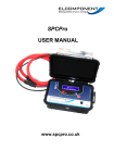
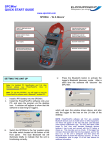
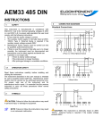
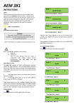
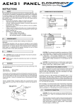
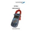
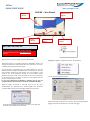
SPCPro QUICK START GUIDE www.spcloggers.com SPCPRO – ‘At a Glance’ Logging Indicator Sleep Button Power Indicator Reset/Start Button Multi-function Display USB Connection Socket SETTING THE UNIT UP Note:For Fordetailed the detailed PC Specification and User Full User Note: PC Specification and Full Manual ease see PowerPackPro Disk or Disk or www.spcloggers.com please see PowerPackPro cloggers.com download download. Install the PowerPackPro software onto your PC. Plug the unit into a mains supply using the cable provided. Example of typical tree diagram Highlight the Logger and right click to select ‘Set Up Survey’ Switch the SPC Pro on by briefly pressing the ‘Reset/Start’ button. The display will illuminate to indicate that the unit is powered up. The unit is switched off by pressing the ‘sleep’ button. Connect the SPC Pro (powered up) to an unused USB port on your PC. Windows will then configure the USB interface for first time use. A ‘found new hardware’ dialogue box will confirm your new hardware is now ready for use. If the hardware interface is not successfully loaded, windows may ask for a disk, or for permission to carry out a web search or the relevant driver. The driver is present on CD supplied with the product under the ‘Drivers’ Folder. In rare cases, particularly on Windows 7 machines, the PC may not recognise that the SPC Pro has been connected. See Additional Notes. The set-up window will then appear With the logger connected to the USB port of your PC, open PowerPackPro. If a ‘Bluetooth Scan’ window appears, this should be cancelled. Within a few seconds the logger will be found by the PC. Press OK and the logger will be added to the tree on the upper left hand side of the desktop as shown below. Select the desired survey duration, “interval” will show the appropriate logging interval for the duration set, and click ‘Set Logger’. NOTE: It is not necessary to have a wall socket voltage connection available to carry out a survey. The SPCPro will continue to operate on battery power for up to two weeks on a fully charged battery. In this case, power and energy values are based on user-defined references. The logger is now set, and can be switched off at this point. The PC Software can be closed down. CONNECTING UP WARNING: Refer to connection information in the User Manual before using the logger to make electrical measurements. Voltage Connection: Simply plug your SPC Pro into a convenient wall socket. Current Connection: The SPCPRO is suitable for use on both single phase and three phase supplies. Current measurement connections are made by clipping the flex-type CTs around conductors as shown in the following diagrams and pictures. NOTE: It is important to be able to identify cables correctly when carrying out electrical surveys. Failure to do so may compromise the accuracy of results obtained. Please refer to Appendix 2 of the Manual for information on UK wiring connections. If you are working outside the UK, additional information may be required. Once connected, start your survey by pressing and holding the ‘start/reset’ button for 5 seconds. Note that the display will ‘count down’ to the survey start. Logging is confirmed by the ‘logging’ led flashing every few seconds. To end your survey, press and hold the sleep button for five seconds. Note that the display will ‘count down’ to the survey close. Surveys will end automatically if the programmed survey duration is reached, or if the power is removed and the battery life exceeded. DOWNLOADING SPC Pro is downloaded as follows: Open PowerPackPro on the PC and establish communication with the logger as detailed above. Click ‘download data’ and follow the on screen instructions to download and display your survey. Full details of the software can be found in the user manual on the CD. . NOTES ADDITIONAL If this happens, ensure that the CD is present in your CD drive and the SPC Pro is connected to your PC. Then proceed as follows: Open “Control Panel” from the Windows ‘Start’ button. In XP, select ‘System’ and click the ‘Hardware’ tab, and then ‘Device Manager’. In Vista & W7 select ‘Device Manager’ directly. From the Device Manager list, select ‘Other Devices’. Note: There will be a yellow warning triangle showing, which may be identified as ‘SPC Pro’. Click on the yellow triangle, and click ‘Update Driver’ Select the option which allows the driver to be installed from a location on the PC (not the automatic search). Browse to the CD location [DRIVE]:\V.2.**.**\SPC----Drivers\ and click ‘next’. Click install, and exit when complete. Note: It may be necessary to load a second driver for the COM port. If the Device Manager list shows a second yellow triangle, click on this and repeat the above procedure NOTE: It is desirable to orientate the CTs with the arrow pointing towards the load as shown, but in most cases not essential as the instrument software will automatically compensate for a reversed connection. NOTE: It is essential that the phase cables are correctly identified when connecting the flex CTs. (See Appendix 2 for more information on phase identification). Unit 5 Southmill Trading Centre, Southmill Road, Bishop’s Stortford, Herts. CM23 3DY 01279 503173 www.spcloggers.com / www.elcomponent.co.uk