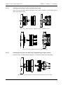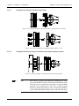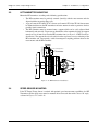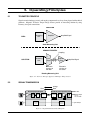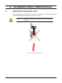
1
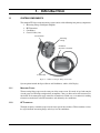
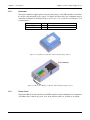
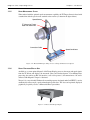
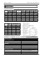
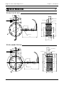
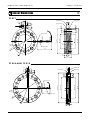
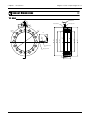
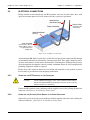
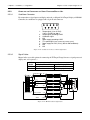
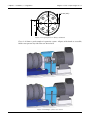
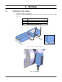
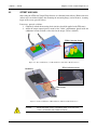
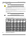
TF Series
Torque Flange Sensors
User’s Manual
Purchase Record
Please record all model numbers and serial numbers of your
Magtrol equipment, along with the general purchase information.
The model number and serial number can be found on either
a silver identification plate or white label affixed to each unit.
Refer to these numbers whenever you communicate with a
Magtrol representative about this equipment.
Model Number:
_____________________________
Serial Number:
_____________________________
Purchase Date:
_____________________________
Purchased From:
_____________________________
While every precaution has been exercised in the compilation of this document to ensure
the accuracy of its contents, Magtrol assumes no responsibility for errors or omissions.
Additionally, no liability is assumed for any damages that may result from the use of the
information contained within this publication.
Copyright
Copyright ©2009 Magtrol, Inc. All rights reserved.
Copying or reproduction of all or any part of the contents of this manual without the express
permission of Magtrol is strictly prohibited.
Second English Edition, revision F – July 2011
Safety Precautions
Warning! In order to minimize risks, it is of utmost
importance to respect the current safety
standards when planning, configuring and
operating the Torque measurement drive
train.
Caution:
Operate the TF Series Torque Flange Sensor with great caution!
The sensor may be irreversibly damaged if impacted mechanically
(fall), chemically (acids) or thermally (hot air, vapor).
1. Make sure that all Magtrol electronic products are earth-grounded, to guarantee personal
safety and proper operation.
2. Check line voltage before operating electronic equipment.
3. Make sure that all rotating parts are equipped with appropriate safety guards.
Note:
4.
5.
6.
7.
Detailed information regarding safety guards can be found in Section
2.6 – Protective Systems.
Periodically check all connections and attachments.
Always wear protective glasses when working close to rotating elements.
Never wear a necktie or baggy clothes when standing close to rotating elements.
Never stand too close or bend over the rotating drive chain.
Qualified Personnel
Persons in charge of installing and operating the TF Series Torque Flange Sensor must have read
and understood this User’s Manual, paying extra close attention to all safety-related information.
The TF Sensor is a high-precision product integrating the most recent measurement techniques.
The sensor can give rise to residual dangers if used and manipulated in a non-compliant way by
unqualified personnel.
This sensor must be handled by qualified personnel according to the technical requirements and the
above-mentioned safety instructions. This is also true when using torque flange accessories.
i
Table of Contents
Magtrol TF Series Torque Flange Sensors
Residual Hazards
Sensor performance is only one element in torque measurement. Safety is of equal importance.
There are possible residual hazards when operating rotating test equipment and it is the responsibility
of the designer, the manufacturer and the user to minimize these hazards.
In addition to general safety precautions, residual hazards are highlighted in this manual by using
the following symbols:
Please read the Preface for a more detailed description of each symbol.
Proper Use
The use of TF Series Torque Flange Sensors is exclusively restricted to torque and rotational speed
measuring tasks and directly-related control and regulating tasks. Any further use shall be deemed
to be improper.
For safe operation, the TF Sensor and its accessories may only be used according to the data and
specifications given in this User’s Manual. Safe operation can be guaranteed only when the sensor
is correctly transported, stored, installed, mounted and used.
Modifications
The TF Torque Flange Sensor and its accessories may not be modified without the express consent
of Magtrol. Magtrol is not be liable for any consequential damages resulting from unauthorized
modifications.
ii
Revisions to This Manual
The contents of this manual are subject to change without prior notice. Should revisions be necessary, updates to all
Magtrol User’s Manuals can be found at Magtrol’s website at www.magtrol.com/support/manuals.htm.
Please compare the date of this manual with the revision date on the website, and then refer to the manual’s Table
of Revisions for any changes/updates that have been made since this edition.
Revision Date
Second English Edition, revision F – July 2011
Table of Revisions
Date
Edition
07/04/11 2nd edition, rev. F
11/12/09 2nd edition, rev. E
06/18/09
03/31/09
03/27/09
06/03/08
2nd edition, rev. D
2nd edition, rev. C
2nd edition, rev. B
2nd edition, rev. A
Change
Section(s)
text concerning parasitic forces updated
4.4
New information about the cardan shaft was added in section 2.2.4.5.
New information about radial forces, axial forces and dynamic limit
was added to section 4.4.
Changed values for TF 220
Added (N/C for 5W conditioner) to pin 7
0.5 mm distance changed to 1.5 mm distance
New design for standard speed sensor
iii
2.2.4.5, 4.4
2.2.4.1
2.5.3.1
2.4.1
1.2, 2.41
Table of Contents
Safety Precautions..........................................................................................................................i
Qualified Personnel............................................................................................................................................i
Residual Hazards.................................................................................................................................................ii
Proper Use.................................................................................................................................................................ii
Modifications.........................................................................................................................................................ii
Revisions to This Manual...............................................................................................................iii
Revision Date................................................................................................................................................................ iii
Table of Revisions..................................................................................................................................................... iii
Table of Contents.......................................................................................................................... iv
Table of Figures......................................................................................................................................................... vi
Preface............................................................................................................................................... vii
Purpose of This Manual........................................................................................................................................vii
Who Should Use This Manual.............................................................................................................................vii
Manual Organization............................................................................................................................................vii
1. Introduction..................................................................................................................................1
1.1 System Components............................................................................................................................................ 1
1.1.1 Measuring Flange................................................................................................................................. 1
1.1.2 HF Transmitter........................................................................................................................................ 1
1.1.3 Conditioner.............................................................................................................................................. 2
1.1.4 Coaxial Cable.......................................................................................................................................... 2
1.1.5 Speed Measurement Option.............................................................................................................. 3
1.1.6 Signal Processor/Display Unit....................................................................................................... 3
1.2 Data Sheet................................................................................................................................................................. 4
2. Installation / Configuration.................................................................................................15
2.1 Initial Cleaning.................................................................................................................................................. 15
2.2 Measuring Flange Mounting....................................................................................................................... 16
2.2.1 Alignment................................................................................................................................................ 16
2.2.2 Coupling Selection............................................................................................................................. 16
2.2.3 Mounting Considerations............................................................................................................... 18
2.2.4 Mounting Procedure......................................................................................................................... 20
2.3 HF Transmitter Mounting............................................................................................................................. 23
2.4 Speed Sensor Mounting................................................................................................................................... 23
2.4.1 Standard Sensors................................................................................................................................ 24
2.4.2 High-temperature Sensors............................................................................................................. 24
2.5 Electrical Connections................................................................................................................................ 25
2.5.1 Connecting the HF Transmitter to the Conditioner . .................................................... 25
2.5.2 Connecting the (Optional) Speed Sensor to the Speed Conditioner....................... 25
2.5.3 Connecting the Conditioner to a Signal Processor/Display Unit........................... 26
2.6 Protective Systems........................................................................................................................................... 27
3. Startup...........................................................................................................................................29
3.1 Powering Up the System.................................................................................................................................. 29
iv
Magtrol TF Series Torque Flange Sensors
Table of Contents
3.2Offset and Gain................................................................................................................................................... 30
4. Measurement Considerations..............................................................................................31
4.1 Dynamic Torque.................................................................................................................................................. 31
4.2 Determining the Natural Frequency of a Drive Train................................................................. 31
4.3 Maximum Dynamic Amplitude...................................................................................................................... 33
4.4 Parasitic Forces.................................................................................................................................................. 34
4.5 Temperature Compensation.......................................................................................................................... 35
5. Operating Principles................................................................................................................36
5.1 Telemetry Principle......................................................................................................................................... 36
5.2 Signal Transmission......................................................................................................................................... 36
5.2.1 Measuring Flange to Conditioner............................................................................................. 37
5.2.2 Conditioner to Measuring Flange............................................................................................. 37
5.2.3 Speed Sensor to Speed Conditioner........................................................................................... 37
6. Troubleshooting / Maintenance..........................................................................................38
6.1 Dismounting the Measuring Flange........................................................................................................ 38
6.2LED Indicators...................................................................................................................................................... 39
6.3 Troubleshooting................................................................................................................................................ 39
6.3.1Output Signal Remains Between -10 V and -12 V.................................................................... 40
6.3.2 No Output Signal / No Reaction.................................................................................................... 41
6.3.3 Signal at ¾ of its Nominal Value When Unloaded............................................................. 42
6.3.4 Unstable Signal.................................................................................................................................... 43
6.3.5 "0" Offset with Normal Signal...................................................................................................... 44
6.4 Repair........................................................................................................................................................................ 45
6.4.1 Defect Report........................................................................................................................................ 45
6.4.2 Returning to Magtrol...................................................................................................................... 45
Magtrol Limited Warranty..........................................................................................................46
Claims.............................................................................................................................................................................. 46
Service Information.......................................................................................................................47
Returning Magtrol equipment for Repair and/or Calibration...................................................... 47
Returning Equipment to Magtrol, Inc. (United States)................................................................. 47
Returning Equipment to Magtrol SA (Switzerland)...................................................................... 47
v
Table of Contents
Magtrol TF Series Torque Flange Sensors
Table of Figures
1. Introduction
Figure 1–1
Figure 1–2
Figure 1–3
Figure 1–4
Figure 1–5
TF Series Torque Flange Sensor Kit..........................................................................................................1
Conditioner for TF 209 – TF 217 Torque Flange Sensors........................................................................2
Electronics Module for TF 218 – TF 220 Torque Flange Sensors............................................................2
Mounted TF Torque Flange Sensor with Speed Measurement Option......................................................3
Model 3410 Torque Display......................................................................................................................3
2. Installation / Configuration
Figure 2–1 Installation Overview..............................................................................................................................15
Figure 2–2 Angular and Radial Misalignment..........................................................................................................16
Figure 2–3 Incorrect Mounting..................................................................................................................................16
Figure 2–4 Coupling Options for Angular Misalignment Correction.......................................................................17
Figure 2–5 Coupling Options for Radial Misalignment Correction..........................................................................17
Figure 2–6 Mounting Flange and Coupling Specifications.......................................................................................18
Figure 2–7 Measuring Flange Spacing.....................................................................................................................19
Figure 2–8 Mounted TF.............................................................................................................................................19
Figure 2–9 Screw Tightening Order...........................................................................................................................20
Figure 2–10 Flange Mounting of TF 209 to TF 212 and TF 220 Sensors.................................................................21
Figure 2–11 Flange Mounting of TF 213 to TF 219 Sensors....................................................................................21
Figure 2–12 Coupling Mounting to Measuring Flange/Mounting Flange Assembly................................................21
Figure 2–13 Coupling Mounting to Measuring Flange (TF 209, 210, 211 and 220)...............................................22
Figure 2–14 Coupling Mounting to Measuring Flange (TF 213 – 219)...................................................................22
Figure 2–15 Mounting Flange to Measuring Flange/Coupling Assembly................................................................22
Figure 2–16 HF Transmitter Installation...................................................................................................................23
Figure 2–17 Standard Speed Sensor Installation.......................................................................................................24
Figure 2–18 High-temperature Speed Sensor Installation........................................................................................24
Figure 2–19 Conditioner Connections.......................................................................................................................25
Figure 2–20 Conditioner Connector Pin Configuration............................................................................................26
Figure 2–21 ER 116 Cable Configuration.................................................................................................................26
Figure 2–22 ER 117 Cable Configuration.................................................................................................................27
Figure 2–23 Spacing Between Flange and Guard.....................................................................................................28
Figure 2–24 Example of Protective System...............................................................................................................28
3. Startup
Figure 3–1
Figure 3–2
Figure 3–3
Figure 3–4
Green and Yellow LEDs...........................................................................................................................29
Red LED..................................................................................................................................................29
Zero Calibration of 1.5 W Conditioner (TF 209 to TF 217 Sensors)......................................................30
Zero Calibration 5 W Conditioner (TF 218 to TF 220 Sensors).............................................................30
4. Measurement Considerations
Figure 4–1 Simplified Physical Drive Train Model...................................................................................................32
Figure 4–2 Drive Train Transfer Curve.....................................................................................................................32
Figure 4–3 Admissible Dynamic Load.......................................................................................................................33
5. Operating Principles
Figure 5–1 Telemetry Principle Applied to TF Torque Flange Sensors.....................................................................36
Figure 5–2 Signal Transmission Block Diagram.......................................................................................................36
6. Troubleshooting / Maintenance
Figure 6–1 Improper Dismounting............................................................................................................................38
vi
Preface
Purpose of This Manual
This manual contains all the information required for the setup, connection and general use of
Magtrol’s Torque Flange Sensors of TF200 series. Please read this manual in its entirety before
operating. Keep the manual in a safe place for quick reference whenever a question should arise.
Who Should Use This Manual
This manual is intended for those who install Torque Flange Sensors on a bench test or to use it
to determine the couple on a transmission chain. The operator is assumed to have the necessary
technical training in mechanical engineering and electronics to enable him to install these Torque
Flange Sensors.
Manual Organization
This section gives an overview of the structure of the manual and the information contained within it.
Some information has been deliberately repeated in different sections of the document to minimize
cross-referencing and to facilitate understanding through reiteration.
The structure of the manual is as follows:
Chapter 1:
Introduction – Contains the technical data sheets for the Torque Flange Sensors
of TF200 series, which describe the units and provide an overview of their possible
applications.
Chapter 2:
Installation/Configuration – Provides the information needed for the
setup and connection of the Torque Flange Sensors.
Chapter 3:
STARTUP – Give the instructions to start the system and adjust the zero of the
measuring chain.
Chapter 4:
MEASUREMENT CONSIDERATIONS – Describes the limits of measures.
Chapter 5:
OPERATING PRINCIPLES – Contains information on lubrication procedures and
provides recommendations for the calibration and checking of the measuring current
and voltage.
Chapter 6:
TROUBLESHOOTING/MAINTENANCE – Give the procedure to follow in case
of breakdown of a Torque Flange Sensors TF.
vii
Preface
Magtrol TF Series Torque Flange Sensors
Conventions Used in This Manual
The following symbols and type styles may be used in this manual to highlight certain parts of the text:
Note:
Caution:
This is intended to draw the operator’s attention to complementary
information or advice relating to the subject being treated. It
introduces information enabling the correct and optimal function
of the product.
This is used to draw the operator’s attention to information,
directives, procedures, etc. which, if ignored, may result in
damage to the material being used. The associated text describes
the necessary precautions to take and the consequences that
may arise if these precautions are ignored.
WARNING! This Introduces Directives, procedures,
precautionary measures, etc. which must be
executed or followed with the utmost care
and attention, otherwise the personal safety
of the operator or third party may be at risk.
The reader must absolutely take note of the
accompanying text, an d act upon it , before
proceeding further.
viii
1. Introduction
1.1
System Components
The complete TF Series torque measuring system consists of the following four primary components:
1. Measuring Flange with Signal Amplifier
2. HF Transmitter
3. Conditioner
4. Coaxial Cable (4 m)
HF Transmitter
Measuring
Flange
Conditioner
(mounted on heatsink)
Coaxial Cable
Figure 1–1 TF Series Torque Flange Sensor Kit
System options include the Speed Sensor and Conditioner, and the 3410 Display
1.1.1
Measuring Flange
The measuring flange represents the rotor part of the torque sensor. It is made of steel and contains
4 strain gauges in full-bridge configuration, an amplifier, a low-pass filter and an A/D converter. It is
fitted with an electromagnetic track around its circumference which acts as an antenna for sending
telemetric transmissions to the HF transmitter and, ultimately, the conditioner.
1.1.2
HF Transmitter
The high-frequency transmitter represents the stator part of the transducer. This transmitter receives
the signal from the measuring flange and relays it to the conditioner.
1
Chapter 1 – Introduction
1.1.3
Magtrol TF Series Torque Flange Sensors
Conditioner
The torque conditioner supplies power to the measuring flange, via the HF transmitter, and collects
the torque signal measured by the system. To display measured values, the conditioner must be
connected to a Magtrol 3410 Torque Display (see Section 1.1.6 – Signal Processor/Display Unit)
or similar device.
TF Model
TF 209 – TF 217
TF 218 – TF 220
Power
1.5 W
5W
Mounting
Mounted on heatsink (for heat dissipation)
Mounted inside electronics module
Figure 1–2 Conditioner for TF 209 – TF 217 Torque Flange Sensors
5 W Conditioner
Figure 1–3 Electronics Module for TF 218 – TF 220 Torque Flange Sensors
1.1.4
Coaxial Cable
The shielded RG-58 coaxial cable between the HF transmitter and the conditioner has an impedance
of 50 Ohms and is 4 meters long (8 m, 12 m, 16 m and 20 m cables are available as an option).
2
Chapter 1 – Introduction
Magtrol TF Series Torque Flange Sensors
1.1.5
Speed Measurement Option
When ordered with the optional speed measurement capability, the TF Torque Sensor is fitted with
a toothed rim with the speed sensor attached to the exterior (as shown in the figure below).
Speed Sensor
TF Measuring Flange
fitted with toothed rim
Connection Cable
Speed Conditioner
Figure 1–4 Mounted TF Torque Flange Sensor with Speed Measurement Option
1.1.6
Signal Processor/Display Unit
Available as a system option, Magtrol's 3410 Torque Display processes the torque and speed signals
from the TF Sensor and displays the measured values and calculated power. For additional data
processing, the unit has an RS-232 interface (cable sold separately) for connection to a PC and is
delivered with Magtrol's Torque 1.0 Software.
Torque 1.0 is a user-friendly Windows® executable program, developed under LabVIEW™, used to
automatically collect torque, speed and mechanical power data. The data can be printed, displayed
graphically or quickly saved as a Microsoft® Excel spreadsheet.
Figure 1–5 Model 3410 Torque Display
3
Chapter 1 – Introduction
1.2
Magtrol TF Series Torque Flange Sensors
Data Sheet
M
AGTROL
TF
Data Sheet
TF Series
Torque Flange Sensor
Features
•
•
•
•
•
•
•
•
•
•
•
•
•
•
•
HF Transmitter
Measuring
Flange
Completetorquemeasuringsystemconsistingof:
• Measuringflangewithsignalamplifier
• HFtransmitter
• Conditioner
• 4mcoaxialcable
Contactlesssignaltransmission:viatelemetry
Torquerange:50N·mto150,000N·m
Highaccuracy:0.1%to0.25%
Overloadcapacity:upto200%(limitofadhesion)
Measuringrange:200%
Brakingtorque:400%
Compact,easy-to-mountdesign
Hightorsionalstiffness
Bearingless:maintenanceandwear-free
Excellentnoiseimmunityandshockresistance
Protectionclass:IP42(IP54optional)
24VDCstandardpowersupply
Integratedspeedsensorandconditioner(option):for
rotationalspeedmeasurement
Hightemperaturecapability:upto125°C(optional)
Coaxial Cable
DesCrIPtION
ThecontactlessdesignoftheTorqueFlangeSensorpermitsagap
ofupto5mm(typically1to3mm)betweentherotorantenna
andHFtransmitter,whichmakesthesignalacquisitioninsensitive
toanyaxialorradialmisalignment.Anotheradvantageofthis
torque measurement system is its insusceptibility to signal
interference—due to the fact that, unlike other designs, the
antennadoesnotneedtobeloopedaroundthemeasuringflange.
Additionally,aprotectivecovercanbemountedclosetotheTF
Sensorwithnoeffectonthesignal.
Withitscompact,bearingless,maintenance-freedesign,thenew
TFTorqueFlangeSensorfromMagtrolbringsmanyappealing
advantagestotorquemeasurementapplications.TheTF’shigh
torsionalrigiditysupportsdirectmountingonthemachineshaft
orflange,avoidingtheuseofcouplingsononeside.Thisallows
easyintegrationintoatestsystem,shortenstheoveralllength
ofthetestbenchandreducescosts.
Based on strain-gauge technology, theTF Sensor’s precise
telemetrysystemenableshighlyaccuratesignaltransmission.
Asignalamplifiermountedinthemeasuringflangeamplifies
the measuring signal, modulates it to high frequency and
transmits it inductively (via the HF transmitter) to the
conditioner. In the conditioner, the digitized torque signal
is transformed into an analog output signal of ±5VDC.
RotationalspeedcanbemeasuredandconvertedtoaTTL
outputsignalwiththeoptionalspeedsensor.
1
Model TF Torque Flange Sensor
aPPLICatIONs
TFTorqueFlangeSensorsmeasurebothstaticanddynamic
torque on stationary and rotating shafts. They are used in
generalcombustionengine,electricmotorandgearboxtest
benches; and can also be mounted inline for active torque
monitoring of transmissions, powertrains, wind generators,
gasturbines,boatengines,etc.
4
www.magtrol.com
Chapter 1 – Introduction
Magtrol TF Series Torque Flange Sensors
Diagrams
TF
BLOCK DIaGraM
HF TRANSMITTER
Switch
4 m Coaxial Cable
RG-58 (50 Ohms)
CONDITIONER
option
Torque
±5 VDC
Torque
Speed sensor
Z pulses/
revolution
Signal
amplifier
Power supply
24 VDC ±10%
350 mA
Rotational
Speed
SPEED CONDITIONER
Rotational speed
TTL
(Option)
Strain Gauge Bridge
for torque measurement
Torque sensor
sYsteM CONFIGuratION
Brake
Frein
TF
Torque Flange
Sensor
Couplemètre
TF
HF
Transmitter
Transmetteur
HF
Motor
under
HF
Transmitter
Moteur
à testertest
Model 3410
Afficheur
couple 3410
Torque de
display
Conditioner
Conditionneur
2
5
M AGTROL
Chapter 1 – Introduction
Magtrol TF Series Torque Flange Sensors
Specifications
TF
MODeL ratINGs
Model
TF 210
TF 211
TF 212
TF 213
TF 214
TF 215
TF 216
TF 217
TF 218
TF 219
TF 220
Model
TF 210
TF 211
TF 212
TF 213
TF 214
TF 215
TF 216
TF 217
TF 218
TF 219
TF 220
rated
Torque
N·m
50
100
200
500
1,000
2,000
5,000
10,000
20,000
50,000
100,000
Sensor
Weight ***
kg
2.1
2.2
2.2
3.3
3.3
5.2
9.3
9.3
42.7
43.3
36.0
overload
accuracy
Capacity
Class
% of R.T.
200%
0.1%
200%
0.1%
200%
0.1%
200%
0.1% *
200%
0.1% *
200%
0.1% *
200%
0.1%
‡ 150%
0.1%
200% 0.20% – 0.25%
‡ 180% 0.20% – 0.25%
‡180% 0.25% – 0.30%
Maximum
Speed
rpm
17,000
17,000
17,000
13,000
13,000
10,000
8,000
8,000
3,000
3,000
3,000
Moment of inertia
kg·m²
2.996 × 10⁻³
3.172 × 10⁻³
3.138 × 10⁻³
7.803 × 10⁻³
7.818 × 10⁻³
1.868 × 10⁻²
4.747 × 10⁻²
4.706 × 10⁻²
9.635 × 10⁻¹
9.724 × 10⁻¹
1.070 × 10 0
lb·ft·s²
2.211 × 10⁻³
2.341 × 10⁻³
2.316 × 10⁻³
5.758 × 10⁻³
5.769 × 10⁻³
1.378 × 10⁻²
3.503 × 10⁻²
3.472 × 10⁻²
7.109 × 10⁻¹
7.175 × 10⁻¹
7.895 × 10⁻¹
*
**
***
‡
number of
Teeth **
Z
70
70
70
91
91
113
133
133
283
283
270
Torsional
Deformation
Stiffness
angle
N·m/rad
°
0.040
7.16 × 10⁴
1.25 × 10⁵
0.046
2.05 × 10⁵
0.056
7.16 × 10⁵
0.040
9.55 × 10⁵
0.060
2.86 × 10⁶
0.040
7.16 × 10⁶
0.040
1.25 × 10⁷
0.046
0.040
2.86 × 10⁷
6.82 × 10⁷
0.042
3.37 × 10⁸
0.017
Available upon request:
• Torque up to 150,000 N·m
• High speed versions
Linearity-hysterese error 0.05% on request
Inductive speed detection available on request.
Add 0.8 kg to 2.8 kg to weight,
depending on configuration,
for electronic devices
attached to the sensor
(transmitter, receiver,
speed conditioner).
Dynamic torque peak
values for Models
TF 217, TF 219 and
TF 220 are due to force
transmission limit of
mounting screws.
Moment of Inertia (X axis)
ratINGs COMMON tO aLL tF seNsOrs
Torque MeaSureMenT
Maximum Dynamic Torque Without Damage (Overload Limit)
SpeeD MeaSureMenT (option)
Number of Teeth
Speed Pick-up Transducer
Minimum Speed Detection
environMenT
Rated Temperature Range
Storage Temperature Range
Extended Temperature Range (option)
Temperature Influence on Zero
Protection Class
inpuT anD ouTpuT SignalS
Power Supply
Torque Output Signal (rated / max)
Passband Frequency
Speed Output (option)
3
400% of Rated Torque
Depending on the size; Refer to Z under Model Ratings
Magnetoresistive
0.5 rpm
+10 °C to +85 °C
-25 °C to +85 °C
-30 °C to +125 °C
0.01% / °C
IP 42 (optional IP 54)
TF 209 – TF 217: 24 V DC ±10%, max 350 mA
TF 218 – TF 220: 100–240 V AC
±5 V DC / ±10 V DC
0 to 1 kHz (-3 dB)
TTL (pulses per revolution corresponds with number of teeth)
6
M AGTROL
Chapter 1 – Introduction
Magtrol TF Series Torque Flange Sensors
Sensor Dimensions
TF
tF 210 tO tF 212
50
20
4.5
Transmitter HF
30
2x
10
30
Rotor antenna
5
Air gap 2 mm
.05
±0
100
39 H7
2.5
Speed sensor
115
18
45.5
4
8x M6x10
8x M6
86
2.5
39 H7
105
M 12x1
Air gap 1.5 mm
0
- 0.2
tF 213 aND tF 214
Rotor antenna
Air gap 2 mm
8x
18
5
M1
0
8x
10.1
30
8x
Transmitter HF
4.5
30
2x
20
10
50
75 H7
.05
3
75 H7
±0
132
1.5
3
M 12x1
10
136.5
Air gap 1.5 mm
Speed sensor
115
2.5
18
0
46 - 0.2
4
7
M AGTROL
Chapter 1 – Introduction
Magtrol TF Series Torque Flange Sensors
Sensor Dimensions
TF
tF 215
10
20
12.2
30
5
8x
30
Air gap 2 mm
Rotor antenna
4.5
8x
2x
Transmitter HF
20
50
3
169.4
90 H7
90 H7
164
M 12x1
Air gap 1.5 mm
3
8x M12
Speed sensor
.05
0 ±0
13
115
6.5
18
0
47 - 0.2
tF 216
Transmitter HF
4.5
Air gap 2mm
8x
14.2
8x
5
30
21.5
Rotor antenna
30
2x
20
10
50
11
8x M14
5.5
15
199.5
110 H7
110 H7
194
M 12x1
Air gap 1.5mm
3
Speed sensor
.05
±0
115
19
16
0
55 - 0.2
5
8
M AGTROL
Chapter 1 – Introduction
Magtrol TF Series Torque Flange Sensors
Sensor Dimensions
TF
tF 217
Transmitter HF
10
50
Air gap 2 mm
20
8x
8x
5
30
24.5
Rotor antenna
16.2
4.5
30
2x
11
199.4
110 H7
194
110 H7
M 12x1
Air gap 1.5 mm
3
8x M16
Speed sensor
5.5
15
.05
±0
115
19
16
0
56.5 - 0.2
tF 218 aND tF 219
Rotor antenna
30
Air gap 3 mm
8x
8x 30.5
47
5
40
Transmitter HF
25
10
60
3
420
290 H7
290 H7
424.5
M12x1
Air gap 1.5 mm
7
16x M30
115
Speed sensor
0
35
.05
±0
24
4
0
55 - 0.2
6
9
M AGTROL
Chapter 1 – Introduction
Magtrol TF Series Torque Flange Sensors
Sensor Dimensions
TF
tF 220
25
40
2x
Transmitter HF
Air gap 3 mm
Rotor antenna
4.5
5
30
10
60
16x M
30
0.1
5±
32
275H7
6
268
275H7
400
6
405
M12x1
115
Speed sensor
Air gap 1.5 mm
2.5
7
10
24
0
104- 0.3
M AGTROL
Chapter 1 – Introduction
Magtrol TF Series Torque Flange Sensors
Speed Sensor Dimensions
TF
staNDarD sPeeD seNsOr
ThestandardspeedsensorisdeliveredwithTFTorqueFlangeSensorsorderedwiththespeedmeasurementoption.
HF
Transmitter
Connection
Cable
(to speed
conditioner)
90
Speed
Sensor
°
115
44
19
M 12x1
10
1.5 mm
44
SW17
2.5
50
17
HIGH-teMPerature sPeeD seNsOr
Thehigh-temperaturespeedsensorisdeliveredwithTFTorqueFlangeSensorsorderedwithboththespeedmeasurementand
extendedtemperaturerangeoptions.
Ø
HF
Transmitter
10°
15
5
.
R5
.5
0
R1
High-temperature
Speed Sensor
6.4
°
90
0.5 mm – 2 mm
20
45
5
O-Ring
4.5
2.4
9
45
Ø15
Ø12
8
11
M AGTROL
Chapter 1 – Introduction
Magtrol TF Series Torque Flange Sensors
Conditioner Dimensions
TF
8.5
60
4.5
83
78
4x
25
A
4x
0
5
95
tF 210 tO tF 217 - staNDarD
5
0
A
47
100
86
14
0
Heatsink
Conditioner
Conditioner - standard version (1.5 W)
mounted on heatsink for heat dissipation
60
8.5
8x
83
78
4.5
25
A
8x
211
121
0
5
95
tF 210 tO tF 217 - wItH sPeeD OPtION
5
0
Torque Conditioner
47
216
202
130
86
14
0
A
Speed Conditioner
Heatsink
Conditioner - speed version (1.5 W)
mounted on heatsink for heat dissipation
9
12
M AGTROL
Chapter 1 – Introduction
Magtrol TF Series Torque Flange Sensors
Conditioner Dimensions
TF
tF 218, tF 219 aND tF 220
A
6
160
6.6
4x
4x
11
135
25
0
350
360
90
0
10
A
Conditioner (5 W)
mounted inside electronics module
10
13
M AGTROL
Chapter 1 – Introduction
Magtrol TF Series Torque Flange Sensors
Ordering Information
TF
OPtIONs aND OrDerING INFOrMatION
MoDel nuMBer:
TF 2
/0
1
MODEL TF 2 1 0 – 2 2 0
SPEED MEAUSUREMENT
• without (standard)
• with (option)
1
2
sYsteM OPtIONs
Model 3410 Torque Transducer Display
MagtroloffersthenewModel3410Displaywhichsupplies
power to any TF Sensor and displays torque, speed and
mechanicalpower.Featuresinclude:
AdjustableEnglish,metricandSItorqueunits
Large,easy-to-readvacuumfluorescentdisplay
Built-inself-diagnostictests
Overloadindication
Tarefunction
RS-232interface
Torqueandspeedoutputs
Closed-boxcalibration
IncludesMagtrolTorque1.0Software
Torque 1.0 Software
Magtrol’sTorque1.0Softwareisaneasy-to-useWindows®
executable program, used to automatically collect torque,
speedandmechanicalpowerdata.Thedatacanbeprinted,
displayed graphically or quickly saved as a Microsoft®
Excelspreadsheet.StandardfeaturesofMagtrol’sTorque1.0
Softwareinclude:peaktorquecapture,multi-axesgraphing,
measuredparametervs.time,adjustablesamplingratesand
polynomialcurvefitting.
MoDel nuMBer:
er 1
-0
CABLE END
• 14-Pin Connector
16
• Pigtail Wires
17
(For use with 3410 Display or DSP6001 Controller)
CABLE LENGTH
• 5m
• 10 m
• 20 m
1
2
3
Couplings
For theTF 210 –TF 219Torque Flange Sensors, Magtrol
offers double-element high-speed couplings to provide
compensation for axial, angular and radial misalignments.
Engagedbyfriction,theyaretorsionally-stiffandminimize
reaction forces. BSD 9200 Series couplings are wear and
maintenance-freeandfeatureacompactdesign.
TF Torque Sensor
TF 210 to TF 211
TF 212
TF 213 and TF 214
TF 215
TF 216
TF 217
TF 218 and TF 219
BSD Moduflex® 9200 Couping
BSD 9200-2.8-200
BSD 9200-4.5-200
BSD 9200-17-200
BSD 9200-28-200
BSD 9200-64-200
BSD 9200-110-200
BSD 9200-640-200
Due to the continual development of our products, we reserve the right to modify specifications without forewarning.
www.magtrol.com
MaGtrOL INC
70 Gardenville Parkway
Buffalo, New York 14224 USA
Phone: +1 716 668 5555
Fax: +1 716 668 8705
E-mail: [email protected]
MaGtrOL sa
Route de Montena 77
1728 Rossens / Fribourg, Switzerland
Phone: +41 (0)26 407 3000
Fax: +41 (0)26 407 3001
14
E-mail: [email protected]
Subsidiaries in:
Germany • France
China • India
Worldwide Network
of Sales Agents
TF-US 02/11
•
•
•
•
•
•
•
•
•
Connection Cables
2. Installation / Configuration
Caution:
before completing the assembly and mounting, it is advised to
first power up the system (see Section 3.1) in order to check the
signal transmission.
rotor antenna
mounting
flange
coupling
TF Measuring
Flange
HF Transmitter
Coaxial Cable
Conditioner
Figure 2–1 Installation Overview
2.1
Initial Cleaning
Prior to installing the TF Series Torque Flange Sensor, all contact surfaces including the measuring
flange, coupling element and mounting flange must be carefully cleaned and degreased. This will
guarantee optimal transmission of the measured torque signal.
Use a soft cloth lightly dampened with alcohol to avoid any abrasion. Be careful to prevent any
alcohol from entering the flange or coming in contact with the rotor antenna during cleaning.
Caution:
Avoid any use of overly aggressive solvents. These can damage
the rotor antenna while cleaning. If necessary, acetone may be
used (instead of alcohol) to remove encrusted deposits.
It is advised to clean all flange and coupling contact surfaces each time the drive train is reconfigured.
15
Chapter 2 – Installation / Configuration
Magtrol TF Series Torque Flange Sensors
2.2
Measuring Flange Mounting
2.2.1
Alignment
The TF Series Torque Flange Sensors are easy to install by design. However, it is important to
achieve the best possible alignment of the various components of the measurement drive train.
Angular and radial misalignments (as illustrated below) must be avoided.
ANGULAR
MISALIGNMENT
RADIAL MISALIGNMENT
Figure 2–2 Angular and Radial Misalignment
The admissible angular and radial misalignment is 0.3° and 0.04 mm, respectively. By using
proper couplings, modest misalignments can be compensated.
Coupling Selection
Driven Element
To avoid excessive extraneous loads, do not couple the driving elements directly to the driven part
of the measuring chain by means of the measuring flange. A coupling is necessary.
Mounting Flange
2.2.2
TF
Measuring
Flange
Figure 2–3 Incorrect Mounting
16
Chapter 2 – Installation / Configuration
Magtrol TF Series Torque Flange Sensors
2.2.2.1
Couplings for Angular Misalignment
In case of a slight angular error, a one-piece lamella coupling, cardan shaft or bellows coupling
may be used.
One-piece Lamella
Cardan Shaft
Bellows
Figure 2–4 Coupling Options for Angular Misalignment Correction
2.2.2.2
Couplings for Radial Misalignment
If the shaft mounting shows a slight radial misalignment, a two-piece lamella coupling, double
cardan shaft or bellows coupling may be used. These elements provide the system with two degrees
of freedom in order to compensate for a slight radial misalignment.
Two-piece Lamella
Double
Cardan Shaft
Bellows
Figure 2–5 Coupling Options for Radial Misalignment Correction
17
Chapter 2 – Installation / Configuration
Mounting Considerations
Mounting Flange and Coupling Specifications
Minimum Tensile Strength
700 N/mm²
Minimum Hardness
25 HRC
Roughness
Ra 1.6
Minimum Face Flatness
0.03 mm
Centering Tolerance Ø
g6
TF
Measuring
Flange
1.6
Coupling
Ø g6
0.03
Rotor Antenna
1.6
Ø g6
0.03
Mounting Flange
2.2.3
Magtrol TF Series Torque Flange Sensors
Figure 2–6 Mounting Flange and Coupling Specifications
•
•
The mounting flange or coupling mounted on the same side as the rotor antenna must have
a diameter equal to or smaller than the rotor antenna diameter.
To achieve the best possible centering of the measuring flange, the mounting flanges and
couplings should use a centering device with a g6 tolerance on the outside diameter as
illustrated in Figure 2–6 Mounting Flange and Coupling Specifications.
The measuring flange is fitted with a centering bore (tolerance H7) on each face.
Note:
•
If the mounting flange is also fitted with a centering bore,
an intermediate centering washer may be used (see Figure
2–8 Mounted TF).
A minimum distance of 10 mm between the main body of the mounting flange and its center
piece (as illustrated in Figure 2–7 Measuring Flange Spacing) is necessary to avoid any
disturbance when transmitting the HF telemetry signal.
18
Chapter 2 – Installation / Configuration
Magtrol TF Series Torque Flange Sensors
TF
Measuring
Flange
Mounting Flange
Rotor Antenna
10 mm (min.)
Figure 2–7 Measuring Flange Spacing
•
•
Check the lengths of the screws and be sure to avoid any contact between the screws and
the opposite part of the measuring flange (see Figure 2–8 Mounted TF).
Ensure a 0.1 to 0.2 mm clearance between the centering hole of the measuring flange and
the mounting flange centering washer.
Exemple de centrage
Mounting
Flange
avec
une rondelle
Centering Washer
min.
clearance
jeu min.
de
0.1-0.2 mm
0.1 mm– 0.2 mm
Measuring Flange
Centering Hole
Figure 2–8 Mounted TF
19
Chapter 2 – Installation / Configuration
2.2.4
Magtrol TF Series Torque Flange Sensors
Mounting Procedure
Since all TF Sensors are reversible, the component that is to be mounted on the same side as the
measuring flange's rotor antenna must be mounted first. The options/mounting orders are as follows:
Option First Step
A
Mounting Flange to Measuring Flange
(see Section 2.2.4.2)
B
Coupling to Measuring Flange
(see Section 2.2.4.4)
2.2.4.1
Second Step
Coupling to Measuring Flange/Mounting
Flange Assembly (see Section 2.2.4.3)
Mounting Flange to Measuring Flange/
Coupling Assembly to (see Section 2.2.4.5)
Mounting Screws
The measuring flange must be mounted with 8.8/10.9/12.9 quality screws applying the specific
fastening torque listed in the following table.
TF Sensor
Model
TF 209
TF 210
TF 211
TF 212
TF 213
TF 214
TF 215
TF 216
TF 217
TF 218
TF 219
TF 220
Fastening Torque [N·m]
Friction
Friction
Coefficient
Coefficient
μ = 0.10
μ = 0.14
Fastening
Screw
Size
Screw
Class
M6
8.8
9.0
11.3
M6
10.9
13.2
16.5
M10
10.9
63
79
M12
M14
M16
10.9
12.9
12.9
108
201
309
137
255
395
M30
10.9
1 775
2 274
M30
10.9
1775
2 274
The mounting screws must be tightened in the following order.
8
1
2
7
6
3
6
5
1
3
4
11
4
5
1 12
7
16
7
8
6
2
TF 209 – TF 219
2
5
13
10
8
15
4
9 14
3
TF 220
Figure 2–9 Screw Tightening Order
Note:
When faced with alternating loads, secure the screws in their threads
with thread locker in order to avoid any loss of preload. Be sure to
prevent the thread locker from spilling over.
20
Chapter 2 – Installation / Configuration
Magtrol TF Series Torque Flange Sensors
2.2.4.2
Attaching the Mounting Flange to the Measuring Flange
Screw the measuring flange onto the mounting flange, firmly attaching it to the driving shaft, as
shown in the figures below.
Figure 2–10 Flange Mounting of TF 209 to TF 212 and TF 220 Sensors
Figure 2–11 Flange Mounting of TF 213 to TF 219 Sensors
2.2.4.3
Attaching the Coupling to the Measuring Flange/Mounting Flange Assembly
Screw the single- or double-element coupling, or cardan shaft, onto the measuring flange.
Figure 2–12 Coupling Mounting to Measuring Flange/Mounting Flange Assembly
21
Chapter 2 – Installation / Configuration
2.2.4.4
Magtrol TF Series Torque Flange Sensors
Attaching the Coupling to the Measuring Flange
Figure 2–13 Coupling Mounting to Measuring Flange (TF 209, 210, 211 and 220)
Figure 2–14 Coupling Mounting to Measuring Flange (TF 213 – 219)
2.2.4.5
Attaching the Mounting Flange to the Measuring Flange/Coupling Assembly
Figure 2–15 Mounting Flange to Measuring Flange/Coupling Assembly
Note:
When using a cardan shaft, Magtrol recommends the latest
generation of GKN series 687 cardan shafts with limited weight.
Do not use the over weighted old cardan shafts. Proper mounting
position of the cardan shaft is neccessary to ensure proper
balancing. Standard applications using a cardan shaft should not
exceed 1500-2000 rpm, depending on size and deflection angle.
22
Chapter 2 – Installation / Configuration
Magtrol TF Series Torque Flange Sensors
2.3
HF Transmitter Mounting
Mount the HF transmitter according to the following specifications:
• The HF transmitter must be perfectly centered (laterally) with the rotor antenna and also
aligned with the measuring flange axis.
• A gap of 2 mm for TF 209 to TF 217 Sensors and 3 mm for TF 218 to TF 220 Sensors must
be maintained between the HF transmitter and rotor antenna in order to guarantee the best
possible signal transmission.
• The HF transmitter must be mounted onto a support which can be easily adjusted both
horizontally and vertically. To prevent any disturbance of the transmitted signal, the support
must be at least 10 mm away from the HF transmitter rim (see Figure 2–16 HF Transmitter
Installation). The support must also be stable in order to prevent excessive vibrating of the
HF transmitter and, consequently, avoid electromagnetic coupling problems between the
rotor antenna and the HF transmitter.
±2 mm Centering Tolerance
10 mm
(min.)
HF Transmitter
Rotor Antenna
2 mm (TF 209–217)
3 mm (TF 218–220)
Support
Figure 2–16 HF Transmitter Installation
2.4
Speed Sensor Mounting
If the TF Torque Flange Sensor is ordered with optional speed measurement capabilities, the HF
Transmitter and the speed sensor must be mounted offset from each other with at least a 90° angle,
as shown in Figures 2–17 and 2–18.
23
Chapter 2 – Installation / Configuration
2.4.1
Magtrol TF Series Torque Flange Sensors
Standard Sensors
The speed sensor must be placed at a 1.5 mm distance from the measuring flange in order to optimize
detection.
HF
Transmitter
Connection
Cable
(to speed
conditioner)
90
°
1.5 mm
Speed
Sensor
Figure 2–17 Standard Speed Sensor Installation
High-temperature Sensors
The high-temperature speed sensor, delivered with TF Torque Flange Sensors ordered with extended
temperature range, must be placed at a 0.5 mm to 2 mm distance from the teeth with a 10° angle to
optimize detection.
HF
Transmitter
10°
°
90
direction
2.4.2
0.5 mm – 2 mm
High-temperature
Speed Sensor
Figure 2–18 High-temperature Speed Sensor Installation
24
Chapter 2 – Installation / Configuration
Magtrol TF Series Torque Flange Sensors
2.5
Electrical Connections
Having installed the measuring flange and HF transmitter, only two electrical cables (three, with
speed measurement option) need to be connected for the system to be operational.
Speed Sensor
Connection Cable
Torque Conditioner
Coaxial Cable
(connects to HF
transmitter)
Speed Conditioner
(optional)
9-pin Connector
(use ER 116 or ER 117
signal cable to connect
to signal processor/
display unit)
Figure 2–19 Conditioner Connections
Avoid running the ER-116/117 signal cable, coaxial cable and speed sensor connection cable through
an environment which may be perturbed by electromagnetic fields. These cables should also not be
run close to transformers, electric motors or motor drives. If running these TF Torque Flange Sensor
cables through such environments cannot be avoided, a minimum distance of 2 feet from potentially
perturbing components should be respected.
Ideally, these cables should be housed in steel conduit and connected to earth ground, to protect
them as much as possible from electromagnetic perturbations.
2.5.1
Connecting the HF Transmitter to the Conditioner
Caution:
Never shorten the coaxial cable. The system has been tuned in
order to optimize the HF transmission using the coaxial cable's
original length (as delivered).
Connect the HF transmitter to the conditioner with the supplied coaxial cable, utilizing the dedicated
connectors. (See Figure 2–19 Conditioner Connections.)
2.5.2
Connecting the (Optional) Speed Sensor to the Speed Conditioner
Connect the speed sensor to the speed conditioner with the supplied connection cable, utilizing the
dedicated connectors. (See Figure 2–19 Conditioner Connections.)
25
Chapter 2 – Installation / Configuration
Magtrol TF Series Torque Flange Sensors
2.5.3
Connecting the Conditioner to a Signal Processor/Display Unit
2.5.3.1
Conditioner Connector
For connection to a signal processor/display unit such as a Magtrol 3410 Torque Display or DSP6001
Controller, the conditioner is equipped with a 9-pin D-sub connector.
1
2
6
1.
2.
3.
4.
5.
6.
7.
8.
9.
3
7
4
8
5
9
Torque signal (-5 to +5 V DC)
(-10 to +10 V DC for 200%)
Torque signal grounding 0 V DC
Calibration signal
N/C
Power supply grounding 0 V DC
TTL speed signal (with speed measurement option)
Power supply 24 V DC (±10%) (N/C for 5W conditioner)
N/C
N/C
Figure 2–20 Conditioner Connector Pin Configuration
Signal Cables
Magtrol offers two cable options for connecting the TF Torque Flange Sensor to a signal processor/
display unit (sold separately).
Cable
Model
ER 116
ER 117
Connectors
On Conditioner Side
On Display Side
9-pin D-sub connector
14-pin Centronics connector
9-pin D-sub connector
none (only pigtail wires)
14
7
Tor que O/P 0.. 5V : wh
0V
: gr n
U
: r ed
0V
: blu
BITE
: br n
8
blk
1
2.5.3.2
Tacho TTL O/P
: yel
gy
Shield
: yel/ blk
Figure 2–21 ER 116 Cable Configuration
26
1
2
3
4
5
6
7
8
9
Chapter 2 – Installation / Configuration
Magtrol TF Series Torque Flange Sensors
gy
Tacho TTL O/P
: yel
U
: r ed
0V
: blu
1
2
3
Tor que O/P 0.. 5V
: wh
4
0V
: gr n
5
BITE
: br n
Tor que O/P
: blk
Shield
: yel/ blk
6
7
8
9
Figure 2–22 ER 117 Cable Configuration
2.6
Protective Systems
Warning!
ALL ROTATING PARTS MUST BE FITTED WITH A PROTECTIVE SYSTEM TO ENSURE THAT THE USER,
AS WELL AS ALL OTHER SURROUNDING people
and OBJECTS, WILL NOT BE INJURED OR DAMAGED AS A RESULT OF THE Drive element BECOMING BLOCKED, A TORQUE OVERLOAD, OR ANY OTHER potential PROBLEM.
The following precautions concerning protective equipment of the drive train must be observed:
• Protective elements must prevent access to moving parts (during test).
• Protective elements must cover all parts which can cause crushing or cutting, and protect
against projections of parts having become loose.
• Avoid attaching protective elements to rotating parts.
• A minimum space of at least 12 mm should be maintained between rotating parts and
protective elements.
27
Chapter 2 – Installation / Configuration
Magtrol TF Series Torque Flange Sensors
12 mm (min.)
Figure 2–23 Spacing Between Flange and Guard
Figure 2–24 shows a good example of a protective system. All parts of the bench are accessible,
but the cover prevents any risk to the user when closed.
Figure 2–24 Example of Protective System
28
3. Startup
3.1
Powering Up the System
1. Switch the system on (power up).
2. Check that all LEDs are illuminated. (If this is not the case, refer to Section 6.2 – LED
Indicators).
LED
Yellow
Green
Red
Indicates
Conditioner is powered up.
Conditioner receives a (return) signal.
Data transmission is OK.
HF transmitter is powered up.
Figure 3–1 Green and Yellow LEDs
Figure 3–2 Red LED
29
Chapter 3 – Startup
3.2
Magtrol TF Series Torque Flange Sensors
Offset and Gain
Offset and gain of TF Series Torque Flange Sensors are calibrated before delivery. However the zero
(offset) may have drifted slightly after mounting the measuring flange (surface flatness, fastening
torque of the screws, parasitic forces).
If necessary, proceed as follows:
1. Completely unload the measuring chain (no force should be applied to the TF Sensor).
2. Adjust the torque output signal by means of the "Offset" potentiometer placed inside the
conditioner in order to obtain a zero value for the torque (0 N·m = 0.000 V).
ZERO Calibration Screw
Figure 3–3 Zero Calibration of 1.5 W Conditioner (TF 209 to TF 217 Sensors)
ZERO Calibration Screw
Conditioner
Power Supply
Unit
Figure 3–4 Zero Calibration 5 W Conditioner (TF 218 to TF 220 Sensors)
Caution:
Never touch the "Gain" adjustment screw. It is only used
after a conditioner replacement or repair.
30
4. Measurement Considerations
Caution:
When performing static measurements, it is possible to go beyond
nominal torque and toward the torque limit which causes
plastic deformation. When exceeding the nominal torque, any
extraneous loads such as axial, shearing and bending forces
must be avoided.
4.1
Dynamic Torque
Static and dynamic measurements differ from one another by the evolution of torque over time. A
constant torque produces static measurements, whereas varying torques can only be determined by
dynamic measurement. TF Torque Flange Sensors have been designed to measure both static and
dynamic torque.
4.2
Determining the Natural Frequency of a Drive Train
Caution:
Critical rotational speeds as well as natural frequencies have
to be taken into consideration in order to avoid resonances and
possible overloading of the TF torque flange sensor.
In order to determine the dynamic torque and frequency response, and to prevent any damage to the
system, it is necessary to calculate the natural frequency of the drive train's torsional oscillations.
The drive train is considered a combination of torsion springs with intermediate flywheel masses.
In the TF Sensor, the deformation area of the measuring flange is the weakest link in the rotating
measuring chain and is subject to torsional vibrations. A good approximation of the dominant
torsional resonant frequency is given in the following formula:
f0 =
1
2π
Ct
J1 + J 2
J1 ⋅ J 2
f0 System natural frequency [Hz]
Ct Torsional stiffness of the flange [N·m/rad]
J1 Moment of inertia (driving element + mounting flange + ½ measuring flange) [kg·m²]
J2 Moment of inertia (driven element + cardan shaft + ½ measuring flange) [kg·m²]
A more detailed analysis of the dynamic system response may require the study of publications on
structural mechanics. However, the following simplified model of a drive train can often be used.
31
Chapter 4 – Measurement Considerations
Magtrol TF Series Torque Flange Sensors
J2
Ct
J1
Figure 4–1 Simplified Physical Drive Train Model
Note:
The natural torsional frequency of the drive train is lower due to the
presence of the TF Torque Flange Sensor. The system’s own natural
frequency must then be recalculated to determine the influence of
the TF Sensor.
The torsion spring describes the behavior of the measuring flange deformation zone. The torsional
stiffness values (Ct) are indicated in the data sheet in Section 1.2. Both moments of inertia (J1 and J2)
are generated by the two deformation areas and can be calculated by adding the moment of inertia
of each individual element. The moment of inertia of the flange is also indicated in the data sheet.
Consult with the suppliers of the couplings, driving element(s) and driven element(s) in order to
obtain details on moment of inertia of the other drive train components.
The natural torsional frequency (f0) determines the response of the torque measuring system and
helps to determine whether rapid variations may influence the measuring system or whether the
torque is amplified or damped by the drive train dynamics. The transfer curve is shown in Figure
4–2 for various quality factor values (Q), depending on the torsional system damping factor. The
graph charts the factor by which the torque will be amplified, depending on the frequency of the
torsional oscillations.
A(f)
A0
22
20
Q = 30
18
16
14
12
Q = 10
10
8
6
Q=3
4
2
0
Q=1
f
f
0,2 0,4 0,6 0,8 1,0 1,2 1,4 1,6 1,8 2,0 0
Figure 4–2 Drive Train Transfer Curve
32
Chapter 4 – Measurement Considerations
Magtrol TF Series Torque Flange Sensors
Example:
Let us assume a natural frequency f0 of 1000 Hz and a quality factor Q=10. A dynamic torque
around 900 Hz (close to the natural frequency) would be read by the TF torque flange sensor
and amplified by a factor of approximately 6. It is important to note that this amplification
is not electrical but mechanical. The risk of overloading the TF Sensor is therefore real.
In practice, the system will be configured and used so as never to get
close to the natural frequency of the measuring chain. The Q value
must, if possible, be "1". For this reason, the drive train torsional
oscillation frequency must be below ~0.5 f0.
Maximum Dynamic Amplitude
The dynamic peak-to-peak amplitude must not exceed 400% of the nominal torque of the TF
Torque Flange Sensor. This is even true with alternating loads. This amplitude must remain within
‑200% Mnominal and +200% Mnominal as shown in the graph below.
200% Mnominal
Dynamic Amplitude
Amplitude
dynamique
= 400% Mnominal
4.3
Note:
0
-200% Mnominal
Figure 4–3 Admissible Dynamic Load
33
Chapter 4 – Measurement Considerations
4.4
Magtrol TF Series Torque Flange Sensors
Parasitic Forces
Caution:
Never exceed admissible limits of torsional momentum, axial or
radial forces. The parasitic forces are to be avoided at most
If the TF Torque Flange Sensor is improperly installed, parasitic forces can act in both radial and
axial directions on the sensor.
Radial forces generate torsional momentum on the TF Sensor which alters its center of gravity. The
resulting imbalance will periodically load the TF sensor proportional to the rotational speed The
influence of this load increases with rotational speed.
Axial or radial forces, misalignment or unbalance will distort the measuring precision of the sensor.
Modulation of axial or radial forces under rotation may cause an anticipated fatigue of the sensor
and shorten its life time.
Note: The values provided in the table are dynamic limits. The dynamic
limit could be much lower depending on the speed of application,
balancing quality, alignment and vibrations.
The following table lists the admissible forces and torque which can be applied to the TF Series
Torque Flange Sensors without damage.
Nominal
Torque
Limit Torque
Rupture Torque
Bending
Torque
N·m
N·m
(150%–200%
Mnominal )
N·m
(400% Mnominal )
N·m
Model
4.5
Admissible Admissible
Axial
Radial
Force
Force
N
N
TF 209
20
40
80
10
150
150
TF 210
50
100
200
25
375
375
TF 211
100
200
400
50
750
750
TF 212
200
400
800
100
1 500
1 500
TF 213
500
1 000
2 000
125
3 750
3 750
TF 214
1 000
2 000
4 000
300
7 500
7 500
TF 215
2 000
4 000
8 000
600
15 000
15 000
TF 216
5 000
10 000
20 000
1 500
37 500
37 500
TF 217
10 000
15 000
40 000
3 000
75 000
75 000
TF 218
20 000
40 000
80 000
6 000
140 000
140 000
TF 219
50 000
90 000
200 000
17 000
200 000
200 000
TF 220
100 000
200 000
400 000
35 000
400 000
400 000
Temperature Compensation
34
Chapter 4 – Measurement Considerations
Magtrol TF Series Torque Flange Sensors
TF Series Torque Flange Sensors are temperature-compensated in their operating range of 20° C and
85° C in a balanced-temperature environment where the temperature on each face of the measuring
flange is the same. When mounted between a warm and a cold element, the TF Sensor displays
variations of measuring accuracy. Mounting the TF Sensor in an environment with a thermal gradient
between the flange faces must be avoided.
35
5. Operating Principles
5.1
Telemetry Principle
Signal transmission between static and rotating components has always been plagued with technical
problems. Magtrol's TF Series Torque Flange Sensors provide an interesting solution by using
telemetry for signal transmission.
AMPLIFIER
+
Measuring
Unit
IDEA:
Amplifier
Amplified Signal
Static Measuring Unit
SENSOR TELEMTRY
Coupling
+
Input
Stage
Measuring
Unit
SOLUTION:
Output
Stage
Amplified Signal
Electronic
circuitry on
the rotor
Electronic
circuitry on
the stator
Rotating Measuring Unit
Figure 5–1 Telemetry Principle Applied to TF Torque Flange Sensors
5.2
Signal Transmission
Energy
Data
Data
Measuring Signal Amplifier
+
Torque
Sensor
N
S
-
~
~
16-bit
A/D
Converter
Conditioner (measurement & power)
Modulator/
Demodulator
Low-pass
Filter
Modulator/
Demodulator
HF
Generator
Signal
Processing
Unit
16-bit
D/A
Converter
-
Gain
(±20%)
Data
Transmission
Connections
Speed
Sensor
Figure 5–2 Signal Transmission Block Diagram
36
~
~
+
Low-pass
Filter
Zero
(±20%)
24 V DC
Output Signal
(UOUT):
0 to ±5 V DC
TTL Output
Chapter 5 – Operating Principles
Magtrol TF Series Torque Flange Sensors
5.2.1
Measuring Flange to Conditioner
The torque signal is generated by strain gauges in a full-bridge configuration that are glued onto the
inside of the measuring flange. This system has proven its efficiency and reliability over many decades
with high measurement accuracy.
The signal delivered by the measuring flange is first amplified, and then sent to a low-pass filter before
being digitalized with 16-bit resolution. Afterwards, the signal is modulated for transmission on an HF
carrier wave (13.56 MHz). All this is carried out in the electronic module located inside the rotor. The
measured signal is then transmitted by induction to the HF transmitter and finally demodulated by the
conditioner.
5.2.2
Conditioner to Measuring Flange
A similar procedure is also used on the conditioner side which transmits the supply voltage (24 V) as
well as the remote calibration signal to the rotor.
5.2.3
Speed Sensor to Speed Conditioner
Using the magnetoresistor principle, the (optional) speed sensor delivers a signal to the speed
conditioner with a frequency proportional to the rotational speed.
37
6. Troubleshooting / Maintenance
6.1
Dismounting the Measuring Flange
When dismounting the measuring flange from the drive train, make sure that all mounting screws
are removed including those which are not visible from outside.
Caution:
Never use the measuring flange for leverage when dismounting
the sensor.
19.421
Figure 6–1 Improper Dismounting
38
Chapter 6 – Troubleshooting / Maintenance
Magtrol TF Series Torque Flange Sensors
6.2
LED Indicators
LED Color
Yellow
Red
If NOT illuminated
Recommendation
Power supply problem.
Check conditioner power supply:
TF 210 – TF 217: 24 V DC (stabilized)
350 mA min.
TF 218 –TF 220: 220 V AC
The conditioner is defect.
Return conditioner to Magtrol.
HF transmitter power supply
problem.
Check conditioner power supply,
HF transmitter connectors and cable.
HF transmitter is defect.
Return HF transmitter to Magtrol.
Signal transmission problem.
Check HF transmitter (see Section 2.3 – HF
Transmitter Mounting).
Measuring flange is defect.
Return entire torque flange sensor (with its
conditioner and HF transmitter) to Magtrol.
Green
6.3
Troubleshooting
The following problems may occur with TF Series Torque Flange Sensors:
1.Output signal (Uout) remains between -10 V and -12 V
2. No output signal / no reaction
3. Signal is at ¾ of its nominal value (calibration value) when the measuring flange is unloaded,
or the signal varies according to the load.
4. Unstable signal
5. "0" offset (signal behaves normally)
The possible causes of these problems are shown in the following flowcharts.
39
Chapter 6 – Troubleshooting / Maintenance
6.3.1
Magtrol TF Series Torque Flange Sensors
Output Signal Remains Between -10 V and -12 V
1
Output signal (UOUT) at ≈ -10 V to -12 V
Check LEDs
on conditioner
Possible causes:
- Conditioner power supply
- Conditioner
Yellow LED
(power supply)
illuminated?
NO
YES
Possible causes:
- Conditioner
- Measuring flange
Green LED
(synchro)
illuminated?
YES
NO
Check
HF transmitter
LED
Possible causes:
- Rotor antenna not correctly
positioned (distance or alignment)
with the rotor
- Measuring flange
- HF transmitter
- Conditioner
YES
LED illuminated?
40
NO
Possible causes:
- HF transmitter
- Conditioner
- Cable
Chapter 6 – Troubleshooting / Maintenance
Magtrol TF Series Torque Flange Sensors
6.3.2
No Output Signal / No Reaction
2
No output signal,
no reaction
Check LEDs
on conditioner
Possible causes:
- Conditioner power supply
- Conditioner
Yellow LED
(power supply)
illuminated?
NO
YES
Possible cause:
- Conditioner
Green LED
(synchro)
illuminated?
NO
41
YES
Possible causes:
- Measuring flange
- Conditioner
Chapter 6 – Troubleshooting / Maintenance
6.3.3
Magtrol TF Series Torque Flange Sensors
Signal at ¾ of its Nominal Value When Unloaded
3
Signal is at ¾ of its nominal value (calibration value)
when the measuring flange is unloaded.
The signal varies according to the load.
Check if system is in
calibration mode
YES
Disable calibration mode
Calibration mode?
NO
Disabling
possible?
YES
END
NO
Possible causes:
- Measuring flange
- Conditioner
Possible causes:
- Wiring between the conditioner
and the display unit
- Display unit
- Conditioner
42
Chapter 6 – Troubleshooting / Maintenance
Magtrol TF Series Torque Flange Sensors
6.3.4
Unstable Signal
4
Unstable signal
Check LEDs on
conditioner
Possible causes:
- Conditioner power supply
- Conditioner
NO
Yellow LED
(power supply on)
illuminated?
YES
Possible causes:
- Measuring flange
- Conditioner
YES
Green LED
(synchro)
illuminated?
NO
Possible causes:
- Rotor antenna not correctly
positioned (distance or alignment)
with the rotor
- Measuring flange
- HF transmitter
- Conditioner
43
Chapter 6 – Troubleshooting / Maintenance
6.3.5
Magtrol TF Series Torque Flange Sensors
"0" Offset with Normal Signal
“0” Offset
(signal reacts normally)
5
- Check if conditioner and measuring
flange are compatible (see S/N)
- Completely unload the measuring
flange
- Adjust the “0” on the conditioner
Possible causes:
- Loaded measuring flange
- Measuring flange
- Conditioner
NO
Adjustable “0”?
YES
END
Note:
If you require additional assistance, please contact Magtrol Customer
Service.
44
Chapter 6 – Troubleshooting / Maintenance
Magtrol TF Series Torque Flange Sensors
6.4
Repair
In case of a defect, please refer to both the Warranty and Service Information located in the back
of this manual.
Caution:
Maintenance must be performed by Magtrol in order to guarantee
future measuring accuracy.
6.4.1
Defect Report
To allow Magtrol to complete the work in the best possible time, it is imperative that the following
information be documented and included with your return shipment:
• Model number, part number (P/N), serial number (S/N), order number and date of
purchase
• Description of the defect and the conditions in which it appeared
• Description of the test bench (drawing, photographs, sketches, etc.)
• Description of the tested object (drawing, photographs, sketches, etc.)
• Description of the test cycle
6.4.2
Returning to Magtrol
1. Carefully pack the complete TF Torque Flange Sensor kit (including HF transmitter,
conditioner and cable).
2. Include the defect report, as described in Section 6.4.1.
3. Follow the procedure outlined in the back of this manual under Service Information
– Returning Equipment to Magtrol SA (Switzerland).
45
Magtrol Limited Warranty
Magtrol, Inc. warrants its products to be free from defects in material and workmanship under normal use and service
for a period of twenty-four (24) months from the date of shipment. Software is warranted to operate in accordance
with its programmed instructions on appropriate Magtrol instruments. This warranty extends only to the original
purchaser and shall not apply to fuses, computer media, or any other product which, in Magtrol’s sole opinion, has
been subject to misuse, alteration, abuse or abnormal conditions of operation or shipping.
Magtrol’s obligation under this warranty is limited to repair or replacement of a product which is returned to the
factory within the warranty period and is determined, upon examination by Magtrol, to be defective. If Magtrol
determines that the defect or malfunction has been caused by misuse, alteration, abuse or abnormal conditions of
operation or shipping, Magtrol will repair the product and bill the purchaser for the reasonable cost of repair. If the
product is not covered by this warranty, Magtrol will, if requested by purchaser, submit an estimate of the repair
costs before work is started.
To obtain repair service under this warranty, purchaser must forward the product (transportation prepaid) and a
description of the malfunction to the factory. The instrument shall be repaired at the factory and returned to purchaser,
transportation prepaid. MAGTROL ASSUMES NO RISK FOR IN-TRANSIT DAMAGE.
THE FOREGOING WARRANTY IS PURCHASER’S SOLE AND EXCLUSIVE REMEDY AND IS IN LIEU
OF ALL OTHER WARRANTIES, EXPRESSED OR IMPLIED, INCLUDING BUT NOT LIMITED TO ANY
IMPLIED WARRANTY OF MERCHANTABILITY, OR FITNESS FOR ANY PARTICULAR PURPOSE OR USE.
MAGTROL SHALL NOT BE LIABLE FOR ANY SPECIAL, INDIRECT, INCIDENTAL, OR CONSEQUENTIAL
DAMAGES OR LOSS WHETHER IN CONTRACT, TORT, OR OTHERWISE.
Claims
Immediately upon arrival, purchaser shall check the packing container against the enclosed packing list and shall,
within thirty (30) days of arrival, give Magtrol notice of shortages or any nonconformity with the terms of the order.
If purchaser fails to give notice, the delivery shall be deemed to conform with the terms of the order.
The purchaser assumes all risk of loss or damage to products upon delivery by Magtrol to the carrier. If a product is
damaged in transit, PURCHASER MUST FILE ALL CLAIMS FOR DAMAGE WITH THE CARRIER to obtain
compensation. Upon request by purchaser, Magtrol will submit an estimate of the cost to repair shipment damage.
46
Service Information
Returning Magtrol equipment for Repair and/or Calibration
Before returning equipment to Magtrol for repair and/or calibration, please visit Magtrol’s Web site at
http://www.magtrol.com/support/rma.htm to begin the Return Material Authorization (RMA) process. Depending on
where the equipment is located and which unit(s) will be returned, you will be directed to either ship your equipment
back to Magtrol, Inc. in the United States or Magtrol SA in Switzerland.
Returning Equipment to Magtrol, Inc. (United States)
When returning equipment to Magtrol, Inc.’s factory in the United States for repair and/or calibration, a completed
Return Material Authorization (RMA) form is required.
1.Visit Magtrol’s Web site at http://www.magtrol.com/support/rma.htm to begin the RMA process.
2.
Complete the RMA form online and submit.
3.
An RMA number will be issued to you via e-mail. Include this number on all return documentation.
4.
Ship your equipment to:
Magtrol, Inc.
70 Gardenville Parkway
Buffalo, NY 14224
Attn: Repair Department
5.
After Magtrol’s Repair Department receives and analyzes your equipment, a quotation listing all the necessary
parts and labor costs, if any, will be faxed or e-mailed to you.
6.
After receiving your repair estimate, provide Magtrol with a P.O. number as soon as possible. A purchase
order confirming the cost quoted is required before your equipment can be returned.
Returning Equipment to Magtrol SA (Switzerland)
If you are directed to ship your equipment to Switzerland, no RMA form/number is required. Just send your equipment
directly to Magtrol SA in Switzerland and follow these shipment instructions:
1.
Ship your equipment to:
Magtrol SA
After Sales Service
Route de Montena 77
1728 Rossens / Fribourg
Switzerland
VAT No: 485 572
2.
Please use our forwarder : TNT • 1-800-558-5555 • Account No 154033
Only ship ECONOMIC way (3 days max. within Europe)
3.
Include the following documents with your equipment:
• Delivery note with Magtrol SA’s address (as listed above)
• Three pro forma invoices with:
•Your VAT number
•Value - for customs purposes only
• Description of returned goods •Origin of the goods (in general, Switzerland)
• Noticed failures
4.
A cost estimate for repair will be sent to you as soon as the goods have been analyzed. If the repair charges
do not exceed 25% the price of a new unit, the repair or calibration will be completed without requiring prior
customer authorization.
47
Testing, Measurement and Control of Torque-Speed-Power • Load-Force-Weight • Tension • Displacement
Magtrol Inc
70 Gardenville Parkway
Buffalo, New York 14224 USA
Phone: +1 716 668 5555
Fax: +1 716 668 8705
E-mail: [email protected]
Magtrol SA
Route de Montena 77
1728 Rossens / Fribourg, Switzerland
Phone: +41 (0)26 407 3000
Fax: +41 (0)26 407 3001
E-mail: [email protected]
www.magtrol.com
Subsidiaries in:
Germany • France
China • India
Worldwide Network
of Sales Agents