1
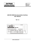
User’s Manual
ND 522/523
English (en)
7/2014
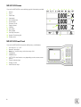
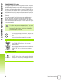
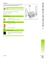
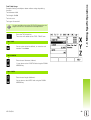
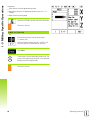
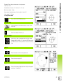
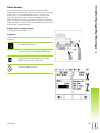
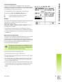
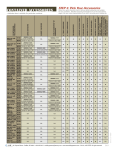
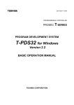
ND 522/523 Screen
View of the ND 522/523 screen defining typical information provided.
1
2
3
4
5
6
7
8
9
10
11
12
13
14
Datum
Tools
Feed Rate
Stopwatch
Unit of Measure
Actual Value
Distance-To-Go
Page Indicator
Set/Zero
Axis Label
Ref Symbol
Soft Key Functions
Graphic Positioning Aid
Display Area
1
2
3
5
4
6
7
8
11
10
14
13
12
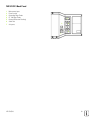
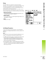
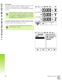
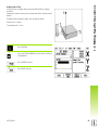
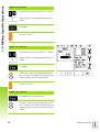
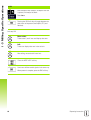
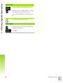
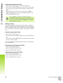
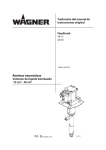
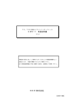
ND 522/523 Front Panel
View of the ND 522/523 front panel defining keys, and features.
1
2
3
4
5
6
7
8
9
2
Axis keys (3) - X, Y, & Z
Numeric input keys
Enter key, confirm entry, and select entry field
CLEAR key
ARROW keys
SOFT KEYS that functions vary depending on the current screen
shown
Power indicatior light
Display screen
Hard Function Keys
9
2
1
8
3
5
7
6
8
4
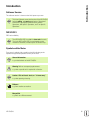
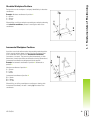
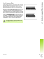
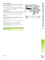
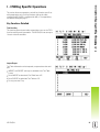
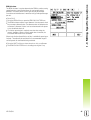
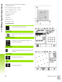
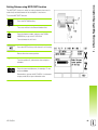
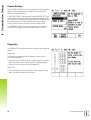
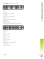
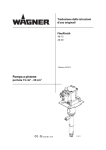
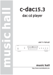
ND 522/523 Back Panel
1
2
3
4
5
6
7
Main power input
Power switch
Grounding Edge Finder
KT 130 Edge Finder
Ground (Protective Earthing)
Serial Port
Axis ports
4
2
1
ND 522/523
5
3
3
4
Introduction
Introduction
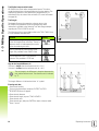
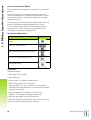
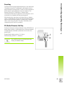
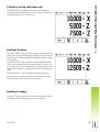
Software Version
The software version is shown on the initial power up screen.
This User's Manual covers the functions of the ND 522/523
for both milling, and turning applications. Operational
information is arranged in three sections: General
Operations, Mill Specific Operations, and Turn Specific
Operations.
ND 522/523
DRO axis availability.
The ND 522/523 DRO is available in three axis form only.
The 3 axis ND 522/523 DRO is used through out this
manual for illustration, and description of function keys.
Symbols within Notes
Every note is marked with a symbol on the left indicating to the
operator the type and/or potential severity of the note.
General Information
e.g. on the behavior of the ND 522/523.
Warning Refer to accompanying documents
e.g. when a special tool is required for a function.
Caution - Risk of electric shock, or “in harms way”
e.g. when opening a housing.
Different
e.g. from machine to machine.
Manual Ref.
e.g. Refer to a different manual.
ND 522/523
5
Introduction
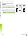
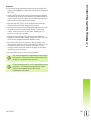
ND 522/523 Fonts
The chart below shows how the different variables (soft keys, hard
keys) are represented within the text of this manual:
Soft keys - SETUP soft key
Hard keys - Enter hard key
6
I Operating Instructions ..... 11
I - 1 Fundamentals of Positioning ..... 12
Datums ..... 12
Actual Position, Nominal Position, and Distance-To-Go ..... 12
Absolute Workpiece Positions ..... 13
Incremental Workpiece Positions ..... 13
Zero Angle Reference Axis ..... 14
Position Encoders ..... 14
Encoder Reference Marks ..... 15
I - 2 General Operations for ND 522/523 ..... 16
Screen Layout ..... 16
General Operation Hard Key Function Overview ..... 17
General Navigation ..... 18
Operating Modes ..... 18
Graphic Positioning Aid ..... 19
Help Screen ..... 19
Data Input Forms ..... 20
Instruction Box messages ..... 20
Error Messages ..... 20
Power Up ..... 21
Reference Mark Evaluation ..... 21
Working without reference mark evaluation ..... 21
ENABLE/DISABLE REF function ..... 22
Setup ..... 23
Job Setup Parameters ..... 23
Units ..... 23
Scale Factor ..... 24
Mirror ..... 24
Diameter Axes ..... 24
Graphic Positioning Aid ..... 25
Status Bar Settings ..... 25
Stopwatch ..... 25
Console Adjustment ..... 26
Language ..... 26
Import/Export ..... 26
DRO Operating Screen Soft Key Function Overview ..... 27
General Operation Key Functions Detailed ..... 28
Set Zero Soft Key ..... 28
1/2 Hard key ..... 29
Calc Hard key ..... 30
ND 522/523
7
I - 3 Milling Specific Operations ..... 31
Key Functions Detailed ..... 31
Tool Hard Key ..... 31
Import/Export ..... 31
Tool Radius Compensation feature ..... 32
Tool Length ..... 32
Sign for the length difference ΔL ..... 32
Entering tool data ..... 32
Tool Table Usage ..... 33
Calling the Tool Table ..... 35
Datum Hard key ..... 35
Probing with a Tool ..... 37
Presetting ..... 39
Absolute Distance Preset ..... 39
Incremental Distance Preset ..... 43
RPM Calculator ..... 45
Circle, and linear Patterns (Milling) ..... 46
Functions for milling patterns ..... 46
Circle Pattern ..... 46
Linear Pattern ..... 49
2nd step: Drill ..... 51
Incline & Arc Milling ..... 52
Incline Milling ..... 52
Arc Milling ..... 55
I - 4 Turning Specific Operations ..... 58
Keys Functions Detailed ..... 58
Turning Specific Display Icons ..... 58
Tool Hard key ..... 58
To access the Tool Table menu: ..... 58
Tool Table Usage ..... 59
Setting tool offsets using TOOL/SET ..... 59
Setting Tool Offset using NOTE/SET Function ..... 60
Datum Hard key ..... 61
Example: Setting a workpiece datum. ..... 61
Preparation: ..... 61
Setting Datums using NOTE/SET Function ..... 63
Taper Calculator Hard Key ..... 64
Presetting ..... 65
RX (Radius/Diameter) Soft Key ..... 65
Vectoring Hard Key ..... 66
Z Coupling (turning applications only) ..... 67
Enabling Z Coupling ..... 67
Disabling Z Coupling ..... 67
8
II Technical Information ..... 69
II - 1 Installation, and Electrical Connection ..... 70
Items Supplied ..... 70
Accessories ..... 70
ND 522/523 Display Unit ..... 70
Mounting Location ..... 70
Installation ..... 70
Electrical connection ..... 70
Electrical requirements ..... 71
Environmental ..... 71
Wiring the power connector ..... 71
Protective earthing (grounding) ..... 71
Preventative maintenance ..... 71
Connecting the Encoders ..... 72
II - 2 Installation Setup ..... 73
Installation Setup Parameters ..... 73
Encoder Setup ..... 73
Display Configuration ..... 74
Coupling ..... 74
Error Compensation ..... 74
Linear Error Compensation ..... 75
Non-Linear Error Compensation ..... 75
Configuring the Compensation Table ..... 76
Reading the Graph ..... 76
Viewing the Compensation Table ..... 76
Exporting the Current Compensation Table ..... 76
Importing a New Compensation Table ..... 76
Backlash Compensation ..... 77
Counter Settings ..... 78
Diagnostics ..... 78
ND 522/523
9
II - 3 Encoder Parameters ..... 79
Example settings for HEIDENHAIN linear encoders ..... 79
Example settings for HEIDENHAIN Rotary encoders ..... 79
Example settings for HEIDENHAIN Angle encoders ..... 79
II - 4 Data Interface ..... 80
USB Port (type “B”) ..... 81
External Operations via USB port ..... 81
II - 5 Measured Value Output ..... 84
Examples of character output at the data interface ..... 84
II - 6 Specifications for Milling ..... 86
II - 7 Specifications for Turning ..... 87
II - 8 Dimensions ..... 88
II - 9 Accessories ..... 89
Accessory ID Numbers ..... 89
ND 522/523 Handle
ID 618025-01 ..... 89
10
Operating Instructions
ND 522/523
11
I - 1 Fundamentals of Positioning
I - 1 Fundamentals of Positioning
Datums
The workpiece drawing identifies a certain point on the workpiece
(usually a corner) as the absolute datum, and perhaps one, or more
other points as relative datums.
The datum setting procedure establishes these points as the origin of
the absolute, or relative coordinate systems. The workpiece, which is
aligned with the machine axes, is moved to a certain position relative
to the tool, and the display is set either to zero, or to another
appropriate value (e.g., to compensate for tool radius).
Actual Position, Nominal Position, and DistanceTo-Go
The position of the tool at any given moment is called the actual
position, 1 while the position that the tool is to move to S is called the
nominal position. The distance from the nominal position to the
actual position R, is called the distance-to-go (Incremental).
12
I Operating Instructions
I - 1 Fundamentals of Positioning
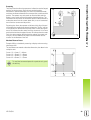
Absolute Workpiece Positions
Each position on the workpiece is uniquely identified by its absolute
coordinates.
Example: Absolute coordinates of position 1:
X = 20 mm
Y = 10 mm
Z = 15 mm
When drilling, or milling a workpiece according to a workpiece drawing
with absolute coordinates, the tool is moving the value of the
coordinates.
Incremental Workpiece Positions
A position can also be referenced to the preceding nominal position.
In this case the relative datum is always the last nominal position.
Such coordinates are referred to as incremental coordinates
(increment = increase). They are also called incremental, or chain
dimensions (since the positions are defined as a chain of dimensions).
Incremental coordinates are designated with the prefix I.
Example: Incremental coordinates of position 3 referenced to
position 2.
Absolute coordinates of position 2:
X = 10 mm
Y = 5 mm
Z = 20 mm
Incremental coordinates of position 3:
IX = 10 mm
IY = 10 mm
IZ = –15 mm
When drilling, or milling a workpiece according to a drawing with
incremental coordinates, the tool is moving by the value of the
coordinates.
ND 522/523
13
I - 1 Fundamentals of Positioning
Zero Angle Reference Axis
The Zero Angle Reference Axis is the 0 degree position. It is defined
as one of the two axes in the plane of rotation. The following table
defines the Zero Angle where the position of the angle is zero for the
three possible planes of rotation.
For angular positions, the following reference axes are defined:
Plane
Zero Angle Reference Axis
XY
+X
YZ
+Y
ZX
+Z
Positive direction of rotation is counterclockwise if the working plane
is viewed in the negative tool axis direction. .
Example: Angle in the working plane X / Y
Angle
Corresponds to the...
+ 45°
... bisecting line between +X, and +Y
+/– 180°
... negative X axis
- 270°
... positive Y axis
Position Encoders
The position feedback encoders convert the movement of the
machine axes into electrical signals. The ND 522/523 constantly
evaluates these signals, and calculates the actual positions of the
machine axes, which it displays as a numerical value on the screen. .
If there is an interruption in power, the calculated position will no
longer correspond to the actual position. When power is restored,this
relationship can be re-establish with the aid of the reference marks on
the position encoders, and the ND 522/523's reference mark
evaluation feature (REF).
14
I Operating Instructions
I - 1 Fundamentals of Positioning
Encoder Reference Marks
Encoders normally contain one, or more reference marks which the
ND 522/523’s Reference Mark Evaluation feature uses to re-establish
datum positions after a power interruption. There are two main
options available for reference marks; fixed, and distance-coded.
Encoders with distance-coded reference marks have marks
separated by a specific encryption pattern that allows the ND 522/523
to use any two pair of marks along the length of the encoder to reestablish the prior datums. This configuration means that the operator
only has to travel a very short distance, any where along the encoder,
to re-establish the datums when the ND 522/523 is turned back on.
Encoders with fixed reference marks have one, or more marks on
fixed intervals. To re-establish the datums correctly, it is necessary to
use the same exact reference mark, during the Reference Mark
Evaluation routine, that was used when the datum was first
established.
The established datums’ cannot be restored from one
power cycle to the next if the reference marks were not
crossed before the datums were set.
ND 522/523
15
I - 2 General Operations for ND 522/523
I - 2 General Operations for
ND 522/523
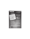
Screen Layout
Status Bar Symbols
1
2
3
4
5
6
7
8
9
10
11
12
13
Datum
Tool
Feed Rate
Job Clock
Unit of Measure
Operating Modes
Page Indicator
Set/Zero
Axis Labels
Ref Symbol
Soft key Labels
Display Area
Near Zero Warning (In Distance-To-Go mode only)
1
2
3
4
5
6
1
7
8
10
12
9
13
11
The ND 522/523 readout provides application-specific features that
allows the most productivity be obtained from manual machine tools.
Status Bar - This displays the current datum, tool, feed rate, job
clock time, unit of measure, operating mode status, page indicator,
and set/zero. See Job Setup for details on setting up the Status
Bar parameters.
Display Area - Indicates the current position of each axis. Also
shows forms, fields, instruction boxes, error messages, and
help topics.
Axis Labels - Indicates axis for corresponding axis key.
Ref Symbols - Indicates current reference mark status.
Soft key Labels - Indicates the various milling, or turning functions.
16
I Operating Instructions
I - 2 General Operations for ND 522/523
General Operation Hard Key Function Overview
The following is a list of Hard keys, and a description of their function
which are located on the front panel of the readout.
Hard Key
Page 1
Hard Key function
Hard key
Symbol
INCREMENTAL Switches display between
/ABSOLUTE
Distance-To-Go (Incremental)
Actual Value (Absolute). (page 18)
1/2 (Mill
Function Only)
Used to divide the current position
by two. (page 29)
CALC
Opens the Calculator functions.
(page 30)
DATUM
Opens the Datum form to set the
datum for each axis. (page 35)
TOOL
Opens the Tool Table. (page 31 for
Milling. page 58 for Turning)
CIRCLE
PATTERN
Opens the Circle Pattern form. This
calculates the hole positions (page
46) for Milling
LINEAR
PATTERN
Opens the Linear Pattern form. This
calculates the hole positions (page
49) for Milling
INCLINE
MILLING, or
VECTORING
Opens the Incline milling form (page
52) for Milling, or the Vectoring
form (page 66) for Turning
ARC MILLING, Opens the Arc milling forms (page
or TAPER CALC 55) for Milling, or the Taper Calc
form (page 64) for Turning
ND 522/523
17
I - 2 General Operations for ND 522/523
General Navigation
Use keypad to enter numeric values within each field.
The Enter key will confirm the entry within a field, and return to the
previous screen.
Press the C key to clear entries, and error messages, or return back
to the previous screen.
SOFT KEY labels show the various milling, or turning functions.
These functions are selected by pressing the corresponding soft key
directly below each soft key label. There are 2 pages of selectable
soft key functions. These are accessed using the LEFT/RIGHT
ARROW keys.
The LEFT/RIGHT ARROW keys move through pages 1, and 2 of the
soft key selectable functions. The current page will be highlighted in
the Status bar at the top of screen.
Use the UP/DOWN ARROW keys to move between fields within a
form, and list boxes within a menu. The orientation of the cursor is
such that it will return to the top once it has reached the bottom of
the menu.
Operating Modes
The ND 522/523 has two operating modes: Distance-To-Go
(incremental), and Actual Value (absolute). The Distance-To-Go
feature (which will be referred to as incremental in this manual)
enables approach to nominal positions by traversing to display value
zero. When working within the incremental mode either enter nominal
coordinates as either incremental, or absolute dimensions. The Actual
Value feature (which will be referred to as absolute in this manual)
always displays the current actual position of the tool, relative to the
active datum. In this mode, all moves are done by traveling until the
display matches the nominal position that is required.
While in the Absolute Mode, if the ND 522/523 is configured for
Milling applications, only the tool length offsets are active. Both the
radius, and length offsets are used in the Distance-To-Go mode to
calculate the amount of “distance-to-go” required to get to the desired
nominal position relative to the edge of the tool that will be doing the
cutting.
If the ND 522/523 is configured for a lathe, all tool offsets are used in
both the Incremental, and Absolute modes.
Press the INCREMENTAL / ABSOLUTE hard key to toggle between
these two modes. To view soft key functions in either Incremental, or
Absolute mode, use the LEFT / RIGHT ARROW keys.
The turning application provides a quick method for coupling the
Z axes position on a 3 axis system. See "Enabling Z Coupling" on page
67.
18
I Operating Instructions
I - 2 General Operations for ND 522/523
Graphic Positioning Aid
When traversing to display value zero (in the incremental mode),
ND 522/523 displays a graphic positioning aid.
ND 522/523 displays the graphic positioning aid in a narrow rectangle
underneath the currently active axis. Two triangular marks in the
center of the rectangle symbolize the nominal position to be reached.
A small square symbolizes the axis slide. An arrow indicating the
direction appears in the square while the axis is moving. This indicates
if the axis is moving towards, or away from the nominal position. Note
that the square does not begin to move until the axis slide is near the
nominal position. For setting up the graphic positioning aid. See
"Graphic Positioning Aid" on page 25 under Job Setup.
Help Screen
The integrated operating instructions provide information, and
assistance in any situation.
To call the operating instructions:
Press the HELP soft key.
Information relevant to the current operation will be displayed.
Use the UP/DOWN ARROW keys if the explanation is spread over
more than one screen page.
To view information on another topic:
Press the LIST OF TOPICS soft key.
Press the UP/DOWN ARROW keys to scroll through the index.
Press the Enter key to select an item.
To leave the operating instructions:
Press the C key.
ND 522/523
19
I - 2 General Operations for ND 522/523
Data Input Forms
Information required for various operational functions, and setup
parameters are entered through a data input form. These forms will
appear after selecting features that require any additional information.
Each form provides specific fields for entering the required
information.
Confirm changes by pressing the Enter key, and for them to become
effective. If changes are not to be saved, press the C key to return to
the previous screen without saving changes.
Instruction Box messages
Whenever a Menu, or Form is open an instruction box will also open
immediately to the right of it. This message box will provide
information to the operator on what the chosen function does, and
present instructions on the available options.
Error Messages
If an error occurs when working with ND 522/523, the message will
appear on the display, and provide an explanation of what caused the
error.
To clear the error message:
Press the C key.
20
I Operating Instructions
I - 2 General Operations for ND 522/523
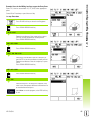
Power Up
Switch on the power (located on the back). The initial
screen will appear. This screen will only appear the
very first time the unit is powered up. The following
steps may have already been completed by the
installer.
Select the proper language by pressing the
LANGUAGE soft key.
Choose the application of either MILL, or TURN.
The APPLIC. [MILL/TURN] soft key toggles
between these two settings.
Next select the number of axes required. When
complete press the Enter hard key.
If necessary, the application can be changed later in
“Installation Setup” under “Counter Settings”.
The ND 522/523 is now ready for operation, and is in the operating
mode Absolute. Each active axis will have a flashing “REF” sign next
to it. At this point the reference mark evaluation should be completed.
Reference Mark Evaluation
The ND 522/523's reference mark evaluation feature automatically reestablishes the relationship between axis slide positions, and display
values that were last defined by setting the datum.
If the axis encoder has reference marks, the “REF” indicator will flash.
. After crossing over the reference marks, the indicator will stop
flashing, and change to non-flashing REF.
Working without reference mark evaluation
The ND 522/523 can be used without crossing over the reference
marks. Press the NO REF soft key to exit the reference mark
evaluation routine, and continue.
Reference marks can be crossed over at a later time, if it becomes
necessary to define datums that can be re-established after a power
interruption. Press the ENABLE REF soft key to activate the reference
mark evaluation routine.
If an encoder is setup without reference marks, then the
REF indicator will not be displayed, and datums will be lost
once power is turned off.
ND 522/523
21
I - 2 General Operations for ND 522/523
ENABLE/DISABLE REF function
The toggling ENABLE/DISABLE soft key, that is present during the
Reference Mark Evaluation routine, allows the operator to select a
specific Reference Mark on an encoder. This is important when using
encoders with Fixed Reference Marks. When the DISABLE REF soft
key is pressed, the evaluation routine is paused, and any reference
marks that are crossed during encoder movement are ignored. When
the ENABLE REF soft key is then pressed, the evaluation routine once
again becomes active, and the next crossed reference mark will be
selected.
Once reference marks for all desired axes are established, press
NO REF soft key to cancel out of routine. Only the axes that are
needed require crossing over the reference marks. If all reference
marks have been found the ND 522/523 will return to the DRO display
screen automatically.
If the reference marks are not crossed over, the
ND 522/523 does not store the datum points. This means
that it is not possible to re-establish the relationship
between axis slide positions, and display values after a
power interruption (switch-off).
For everyday power up; turn on power, and press any
key.
Cross over the reference marks (in any order).
- ALTERNATIVE METHOD Press DISABLE REF soft key, and cross over
reference marks.
Move encoder to desired fixed reference mark. Press
ENABLE REF soft key, and cross over reference
mark.
- ALTERNATIVE METHOD Do not cross over the reference marks, and press the
NO REF soft key. Note: In this case the relationship
between axis slide position, and display value will be
lost after a power interruption.
22
I Operating Instructions
I - 2 General Operations for ND 522/523
Setup
ND 522/523 offers two categories for setting up operating
parameters. These categories are: Job Setup, and Installation Setup.
The Job Setup parameters are used to accommodate specific
machining requirements for each job. Installation Setup is used to
establish encoder, and display parameters.
The Job Setup menu is accessed by pressing the SETUP soft key.
When in the Job Setup menu, the following soft keys will be available:
INSTALLATION SETUP
Press to begin accessing the Installation Setup parameters. See
"Installation Setup Parameters" on page 73.
IMPORT/EXPORT
Press to begin importing, or exporting operating parameters. See
"Import/Export" on page 26.
HELP
Will open on-line help.
Job Setup Parameters
To view, and change Job Setup parameters use the UP/DOWN
ARROW keys to highlight the parameters of interest, and press the
Enter key.
Units
The UNITS form is used to specify the preferred display units, and
format. The system powers up with these settings in effect.
Inch/MM - Measurement values are displayed, and entered in the
units selected in the LINEAR field. Choose between inch, or
millimeter by pressing the INCH/MM soft key. Also the unit of
measure can be selected by pressing the INCH/MM soft key in
either Incremental mode, or Absolute.
Decimal Degrees, Radians, or Degrees/Minutes/Seconds (DMS) The ANGULAR field affects how angles are displayed, and entered
into forms. Choose between DECIMAL DEGREES, RADIANS, or
DMS using the soft key.
ND 522/523
23
I - 2 General Operations for ND 522/523
Scale Factor
The scale factor may be used to scale the part up, or down. All encoder
movements are multiplied by the scale factor. A scale factor of 1.0
creates a part with the exact size as dimensioned on the print.
The numeric keys are used to enter a number greater than zero. The
number range is 0.1000 to 10.000. A negative value may also be
entered.
The scale factor settings will be retained on a power cycle.
When the scale factor is a value other than 1, the scaling symbol
is shown on the axis display.
The ON/OFF soft key is used to disable the current scale factors
Mirror
A scale factor of -1.00 will produce a mirror image of the
part. A part can be both mirrored, and scaled at the same
time.
Diameter Axes
Select Diameter Axes to set which axes can be displayed in either
radius, or diameter values. ON indicates that the axis position will be
displayed as a diameter value. When OFF, the Radius/Diameter
feature does not apply. For turning applications see page 65 for the
Radius/Diameter feature.
Cursor to DIAMETER AXES, and press Enter.
The cursor will be in the X field. Depending on the parameter used
for that axis press the ON/OFF soft key to turn feature on, or off.
Press Enter.
24
I Operating Instructions
I - 2 General Operations for ND 522/523
Graphic Positioning Aid
The GRAPHIC POSITIONING AID form is used to configure the bar
graph that is shown below the axes’ display in Incremental mode.
Each axis has its own range.
Press the ON/OFF soft key to enable, or simply begin entering
values using the numeric keys. The current position box will begin
moving when the position is within range.
Status Bar Settings
The Status Bar is the segmented bar at the top of the screen which
displays current datum, tool, feed rate, stop watch, and page indicator.
Press the ON/OFF soft key for each setting to be displayed.
Stopwatch
The stopwatch shows the hours (h), minutes (m), seconds (s). It
operates like a stop watch showing elapsed time. (The watch starts
timing from 0:00:00).
The elapsed time field shows the total accumulated time from each
interval.
Press the START/STOP soft key. The status field will read
RUNNING. Press it again to stop time from elapsing.
Press RESET to reset the elapsed time. Resetting will stop the
watch if it is running.
Pressing the DECIMAL KEY while in operating mode, will
also stop, and start the clock. Pressing the ZERO key will
reset the clock.
ND 522/523
25
I - 2 General Operations for ND 522/523
Console Adjustment
The LCD’s contrast can be adjusted either by using the soft keys in
this form, or by using the Up/Down arrow keys on the keypad in either
operating mode. The contrast may need to be adjusted due to
variations in ambient lighting, and operator preference. This form is
also used to set the display saver’s idle time-out. The display saver
setting is the amount of time the system is idle before the LCD
switches to screen saver mode. The idle time may be set from 30 to
120 minutes. The display saver can be disabled during the current
power cycle.
Language
The ND 522/523 supports multiple languages. To change the language
selection:
Press the LANGUAGE soft key until the desired language selection
appears on the soft key, and the form.
Press Enter to confirm the selection.
Import/Export
Operating parameter information can be imported, or exported over
the USB port (See "USB Port (type “B”)" on page 81).
Press the IMPORT/EXPORT soft key in the Setup screen.
Press IMPORT to download operating parameters from a PC.
Press EXPORT to upload the current operating parameters to a PC.
To exit, press the C key.
26
I Operating Instructions
I - 2 General Operations for ND 522/523
DRO Operating Screen Soft Key Function
Overview
There are two pages of soft key functions in the operating screen to
select from. Use the LEFT/RIGHT ARROW keys to cursor through
each page. The page indicator in the Status bar will show the page
orientation. The darkened page indicates the page currently being
viewed.
Soft Key
Page 1
Soft Key function
HELP
Opens on-screen help
instructions. (page 19)
INCH/MM
Toggles between inch, and
millimeter units. (page 23)
RADIUS/
DIAMETER
Toggles between radius, and
diameter displays This function is
for Turning applications only. (page
65)
SET/ZERO
Toggles between Set Zero
functions. Used with individual
axis keys. (page 28)
Soft Key
Page 2
Soft Key function
SETUP
Opens the Job Setup menu, and
provides access to the installation
Setup soft key. (page 23)
ENABLE REF
Press when ready to identify a
reference mark. (page 21)
ND 522/523
Soft key
Symbol
Page Indicator
Soft key
Symbol
27
I - 2 General Operations for ND 522/523
General Operation Key Functions Detailed
This section details the soft key functions that are the same, whether
the ND 522/523 is configured for Mill, or Turn applications.
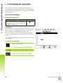
Set Zero Soft Key
The SET/ZERO soft key is a key that determines the effect of pressing
an Axis key. This key is a toggle key, switching the functionality
between Set, and Zero. The current state is indicated in the Status Bar.
When the state is Set, and the ND 522/523 is in Absolute mode,
selecting an Axis key opens the DATUM form for the selected axis. If
the ND 522/523 is in Incremental mode, a PRESET form opens.
Set/Zero Indicator
When the state is zero, and the ND 522/523 is in Absolute mode,
selecting an Axis key sets the datum for that axis to zero at the current
position. If it is in Incremental mode, the current incremental value is
set to zero.
If the ND 522/523 is in Absolute mode, and the state of
SET/ZERO is zero, pressing any Axis key resets the current
datum to zero at the current location for that axis.
28
I Operating Instructions
I - 2 General Operations for ND 522/523
1/2 Hard key
The 1/2 hard key is used to find the half-way (or midpoint) between
two locations along a selected axis of a workpiece. This can be
performed in either Incremental, or Absolute mode.
This feature will change datum locations when in Absolute
mode.
Example: Finding the midpoint along a selected axis
X dimension: X = 100 mm
Midpoint: 50 mm
MOVE TO 1ST POINT
Move tool to first point.
SET ZERO soft key must be set to Zero.
ZERO AXIS, AND MOVE TO 2ND POINT
Select the X axis key and
move to second point.
PRESS 1/2, AND MOVE TO ZERO
Press 1/2 hard key, then press the X axis key, and
move until zero is reached. This is the midpoint
location.
ND 522/523
29
I - 2 General Operations for ND 522/523
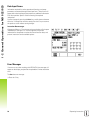
Calc Hard key
ND 522/523’s calculator is capable of handling everything from simple
arithmetic to complex trigonometry, and RPM calculations.
Press the CALC hard key to access the STANDARD/TRIG, and RPM
soft keys.
When more than one calculation is entered into a numeric
field, the calculator will perform multiplication, and division
before it performs addition, and subtraction. If this were to
be entered: 3 + 1 ÷ 8, ND 522/523 will divide one by eight,
then add three for an answer of 3.125.
Trig functions contain all trig operators as well as, square, and square
root. When calculating the SIN, COS, or TAN of an angle, enter the
angle first, and then press the appropriate soft key.
Angle values use the current angle format selection of
decimal degrees, or radians.
30
I Operating Instructions
I - 3 Milling Specific Operations
I - 3 Milling Specific Operations
This section discusses operations, and soft key functions specific to
milling applications only. Soft key functions that are the same,
whether the ND 522/523 is configured for Mill, or Turn applications,
are detailed starting on page 17.
Key Functions Detailed
Tool Hard Key
This hard key opens the tool table, and provides access to the TOOL
form for entering a tool’s parameters. The ND 522/523 can store up to
16 tools within the tool table.
Import/Export
Tool Table information can be imported, or exported over the serial
port.
IMPORT, and EXPORT soft keys are available in the Tool Table
screen.
Press IMPORT to download a Tool Table from a PC.
Press EXPORT to upload the Tool Table to a PC.
To exit, press the C key.
ND 522/523
31
I - 3 Milling Specific Operations
Tool Radius Compensation feature
ND 522/523 has a tool radius compensation feature. This allows
workpiece dimensions to be entered directly from the drawing. The
displayed Incremental is then automatically lengthened (R+), or
shortened (R–) by the value of the tool radius. (For more information
see page 39).
Tool Length
The length offset may be entered as a known value, or the
ND 522/523 may determine the offset automatically. More
information is available in the following Tool Table Usage example
regarding the TEACH LENGTH soft key.
The following soft keys are available while in the TOOL TABLE form,
or in the individual tool data form:
Function
Soft key
This key allows the operator to select which axis
all the tool length offsets will effect. The tool’s
diameter values will subsequently be used to
offset the remaining two axes.
Press to automatically enter the tool offset
length. Only available in the LENGTH field.
This will open the TOOL TYPES form for
selection. Only available in TYPE field.
Sign for the length difference ΔL
If the tool is longer than the reference tool: ΔL > 0 (+)
If the tool is shorter than the reference tool: ΔL < 0 (–)
The tool length is the difference in length ΔL between the
tool, and the reference tool. The reference tool is indicated
by T1.
The length difference is indicated with the “Δ“ symbol.
Entering tool data
Choose tool hard key
Cursor to the desired tool, and press ENTER. The TOOL
DESCRIPTION form will appear.
Enter the tool diameter.
Enter the tool length, or press TEACH LENGTH.
Enter the tool units.
Enter the tool type, and press ENTER to return to the tool table.
Press C to exit.
32
I Operating Instructions
I - 3 Milling Specific Operations
Tool Table Usage
Example: Setting a workpiece datum without using the probing
function.
Tool diameter 2.00
Tool length: 20.000
Tool unit: mm
Tool type: flat end mill
It is also possible to have the ND 522/523 determine the
length of an offset. See alternative example below.
Press the TOOL hard key.
The cursor will default to the TOOL TABLE form.
TOOL TABLE
Cursor to the tool to be defined, or enter the tool
number. Press Enter.
TOOL DIAMETER
Enter the tool diameter (2.0mm).
Cursor down to the LENGTH field using the DOWN
ARROW key.
TOOL LENGTH
Enter the tool length (20.0mm) .
Cursor down to the UNITS field using the DOWN
ARROW key.
ND 522/523
33
I - 3 Milling Specific Operations
- ALTERNATIVE METHOD It is also possible to have ND 522/523 determine an
offset. This method involves touching the tip of each
tool to a common reference surface. This allows
ND 522/523 to determine the difference between the
length of each tool.
Move the tool until its tip is touching the reference
surface.
Press the TEACH LENGTH soft key. ND 522/523 will
calculate an offset relative to this surface.
Repeat the procedure for each additional tool using
the same reference surface.
Only the tools set using the same reference surface may be
changed without having to reset the datum.
If the tool table already contains tools in which the length
has been set, the reference surface should first be
established using one of them. If not,it will not be possible
to switch between the new tools, and the existing tools
without having to re-establish the datum. Before adding the
new tools, select one of the tools from the tool table. Touch
the tool to a reference surface, and set the datum to 0.
- TOOL UNIT Enter the TOOL UNIT (inch/mm).
Cursor down to the TOOL TYPE field.
TOOL TYPE
Press TOOL TYPES soft key. Select from list of tools,
and press Enter
34
I Operating Instructions
I - 3 Milling Specific Operations
Calling the Tool Table
Before machining starts, select the tool to be used from the tool table.
ND 522/523 then takes into account the stored tool data when
working with tool compensation.
Tool call
Press the TOOL hard key.
TOOL NUMBER
Use the UP/DOWN ARROW keys to cursor through
the selection of tools (1-16). Highlight the tool to be
used.
Verify the proper tool has been called, and press the
C key to exit.
Datum Hard key
Datum settings define the relationships between the axis positions,
and the display values.
The easiest way to set datum points is to use the ND 522/523's
probing function when probing the workpiece with an edge of a tool.
Datum points can also be set in the by touching the edges of the
workpiece, one after the other with a tool, and manually entering the
tool positions as datum points (see examples following this page).
The datum table can hold up to 10 datum points. In most cases this
will eliminate from having to calculate the axis travel when working
with complicated workpiece drawings containing several datums.
ND 522/523
35
I - 3 Milling Specific Operations
Example: Setting a workpiece datum without using the probing
function.
Tool diameter: D = 3 mm
Axis sequence in this example: X - Y - Z
Preparation: Set the active tool to the tool that will be used to set the
datum
Press the DATUM hard key.
Cursor will be in the DATUM NUMBER field.
Enter the datum number, and press the DOWN
ARROW key to go to the X axis field.
Touch the workpiece at edge 1.
DATUM SETTING X
Enter the position of the tool center (X = – 1.5 mm)
and
press the DOWN ARROW key to advance to the Yaxis.
Touch the workpiece at edge 2.
DATUM SETTING Y
Enter the position of the tool center (Y = – 1.5 mm).
Press the DOWN ARROW key.
Touch the workpiece surface.
DATUM SETTING Z = + 0
Enter the position of the tool tip (Z = 0 mm) for the Zcoordinate of the datum. Press Enter.
36
I Operating Instructions
I - 3 Milling Specific Operations
Probing with a Tool
Using a tool to set datum points using the ND 522/523's probing
functions.
Preparation: Set the active tool to the tool that will be used to set the
datum.
Example: Probe workpiece edge, and set edge as datum
Datum axis: X =0 mm
Tool diameter D = 3 mm
Press DATUM.
Press the DOWN ARROW key until the X AXIS field
is highlighted.
Press PROBE soft key.
Press EDGE soft key.
ND 522/523
37
I - 3 Milling Specific Operations
PROBE IN X
Touch workpiece edge.
Store the position of the edge by pressing the NOTE
soft key.The NOTE soft key is useful when
determining tool data by touching the workpiece in
the absence of an edge finder with feedback. To avoid
losing the position value when the tool is retracted,
press the NOTE soft key to store the value while it is
in contact with the workpiece edge. The location for
the touched edge will take into account the diameter
of the tool in use (T:1, 2...), and the last direction the
tool was moved prior to pressing the NOTE soft key.
Retract the tool from the workpiece.
ENTER VALUE FOR X
Enter coordinate of the edge
and
press Enter.
38
I Operating Instructions
I - 3 Milling Specific Operations
Presetting
The Preset function allows the operator to indicate the nominal (target)
position for the next move. Once the new nominal position
information is entered the display will switch to Incremental mode,
and show the distance between the current position, and the nominal
position. The operator now only needs to move the table until the
display is zero, and he will be at the required nominal position. The
information for the location of the nominal position can be entered as
an absolute move from the current datum zero, or as an incremental
move from the current nominal position.
Presetting also allows the operator to indicate which side of the tool
will be doing the machining at the nominal position. The R+/- soft key
in the Preset form defines the offset that will be in effect during the
move. R+ indicates that the center line of the current tool is in a more
positive direction than the edge of the tool. R- indicates that the center
line is in a more negative direction than the edge of the current tool.
Using R+/- offsets automatically adjusts the incremental value to
account for the diameter of the tool.
Absolute Distance Preset
Example: Milling a shoulder by traversing to display value zero using
absolute position
The coordinates are entered as absolute dimensions; the datum is the
workpiece zero.
Corner 1: X = 0 mm / Y = 20 mm
Corner 2: X = 30 mm / Y = 20 mm
Corner 3: X = 30 mm / Y = 50 mm
Corner 4: X = 60 mm / Y = 50 mm
To recall the last entered preset for a particular axis, press
the axis key.
ND 522/523
39
I - 3 Milling Specific Operations
Preparation:
Select the tool with the appropriate tool data.
Pre-position the tool to an appropriate location (such as X = Y =
-20 mm).
Move the tool to milling depth.
Press the SET/ZERO soft key to be in the Set mode.
Press the Y axis key
NOMINAL POSITION VALUE
Enter nominal position value for corner point 1:
Y = 20 mm, and
select tool radius compensation R + with R+/- soft
key. Press until R+ is shown next to axis form.
Press Enter.
Traverse the Y axis until the display value is zero. The
square in the graphic positioning aid is now centered
between the two triangular marks.
Press the X axis key
40
I Operating Instructions
I - 3 Milling Specific Operations
NOMINAL POSITION VALUE
Enter nominal position value for corner point 2:
X = +30 mm,
select tool radius compensation R – with R+/- soft
key. Press twice until R+ is shown next to axis form.
Press Enter.
Traverse the X axis until the display value is zero. The
square in the graphic positioning aid is now centered
between the two triangular marks.
Press the Y axis key
ND 522/523
41
I - 3 Milling Specific Operations
NOMINAL POSITION VALUE
Enter nominal position value for corner point 3:
Y = +50 mm,
select tool radius compensation R + with R+/- soft
key, and press until R+ is shown next to axis form.
Press Enter.
Traverse the Y axis until the display value is zero. The
square in the graphic positioning aid is now centered
between the two triangular marks.
Press the X axis key
NOMINAL POSITION VALUE
Enter nominal position value for corner point 4:
X = +60 mm,
select tool radius compensation R +, and press
Enter.
Traverse the X axis until the display value is zero. The
square in the graphic positioning aid is now centered
between the two triangular marks.
42
I Operating Instructions
I - 3 Milling Specific Operations
Incremental Distance Preset
Example: Drilling by traversing to display value zero with incremental
positioning
Enter the coordinates in incremental dimensions. These are indicated
in the following (and on the screen) with a preceding I. The datum is
the workpiece zero.
Hole 1 at: X = 20 mm / Y = 20 mm
Distance from hole 2 to hole 1: XI = 30 mm / YI = 30 mm
Hole depth: Z = –12 mm
Operating mode: INCREMENTAL
Press the SET/ZERO soft key to be in the Set mode.
Press the X axis key.
- NOMINAL POSITION VALUE -
Enter nominal position value for hole 1: X = 20 mm,
and ensure no tool radius compensation is active.
Press the DOWN ARROW key.
NOMINAL POSITION VALUE
Enter nominal position value for hole 1: Y = 20 mm.
Ensure no tool radius compensation is showing.
Press the DOWN ARROW key.
NOMINAL POSITION VALUE
Enter the nominal position value for the hole depth:
Z = –12 mm. Press Enter.
Drill hole 1: Traverse the X, Y, and Z axis until the
display value is zero. The square in the graphic
positioning aid is now centered between the two
triangular marks.
Retract the drill.
Press the X axis key
ND 522/523
43
I - 3 Milling Specific Operations
NOMINAL POSITION VALUE
Enter nominal position value for hole 2: X = 30 mm,
mark the input as an incremental dimension, press I
soft key.
Press Enter.
Press the Y axis key.
NOMINAL POSITION VALUE
Enter nominal position value for hole 2: Y = 30 mm,
mark the input as an incremental dimension, press I
soft key.
Press Enter.
Traverse the X, and Y axes until the display value is
zero. The square in the graphic positioning aid is now
centered between the two triangular marks.
Press the Z axis key.
NOMINAL POSITION VALUE
Press Enter (uses last entered preset).
Drill hole 2: Traverse Z axis until the display value is
zero. The square in the graphic positioning aid is now
centered between the two triangular marks. Retract
the drill.
44
I Operating Instructions
I - 3 Milling Specific Operations
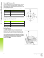
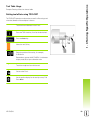
RPM Calculator
The RPM calculator is used to determine the RPM (or surface cutting
speed) based on a specified tool (part, for turning applications)
diameter. The values shown in this Figure are only an example.
Consult the tool manufacturer’s manual to verify spindle speed ranges
per tool.
Press CALC.
Press the RPM soft key to open the RPM CALCULATOR form.
The RPM calculator requires a tool diameter. Use the numeric hard
keys to enter a diameter value. The diameter value will default to the
current tool’s diameter. If there is no last value entered in this power
cycle, the default value is 0.
If a surface speed value is required, enter the value using the
numeric hard keys. When a surface speed value is entered, the
associated RPM value will be calculated.
When in the Surface Speed field, a soft key is available for opening online help. The table may be consulted for a recommended range of
surface speeds for the material being machined.
Press the UNITS soft key to show the units as inch, or millimeter.
The RPM CALCULATOR form is closed by pressing the C key.
ND 522/523
45
I - 3 Milling Specific Operations
Circle, and linear Patterns (Milling)
This section describes the hole pattern functions for Circle, and Linear
patterns.
Press the circle pattern, or linear pattern hard keys to select the
desired hole pattern function, and enter the required data. This data
can usually be taken from the workpiece drawing (e.g. hole depth,
number of holes, etc.).
With hole patterns, the ND 522/523 then calculates the positions of all
the holes, and displays the pattern graphically on the screen.
The View Graphic enables verification of the hole pattern before
machining starts. It is also useful when: selecting holes directly,
executing holes separately, and skipping holes.
Functions for milling patterns
Function
Soft key
Press this to see the layout of the current
pattern.
Press to go to previous hole.
Press to manually advance to the next hole.
Press this to use the existing position.
Press to end drilling.
Circle Pattern
Information required:
Pattern type (full, or segment)
Holes (number of)
Center (center of circle pattern in pattern plane)
Radius (defines radius of the circle pattern)
Start angle (angle of 1st hole in the pattern) - The start angle is
between the zero angle reference axis, and the first hole ( for added
information see page 14).
Step angle (optional: this only applies if creating a circle
segment.) - The step angle is the angle between holes.
Depth (the target depth for drilling in the tool axis)
ND 522/523 calculates the coordinates of the holes which the tool can
then be moved to by traversing to display value zero.
46
I Operating Instructions
I - 3 Milling Specific Operations
Example: Enter data, and execute a circle pattern.
Holes (no. of): 4
Coordinates of center: X = 10 mm / Y = 15 mm
Bolt circle radius: 5 mm
Start angle: (Angle between X axis, and 1st hole): 25°
Hole depth: Z = -5mm
1st step: Enter data
Press CIRCLE PATTERN hard key.
PATTERN TYPE
Enter the type of circle pattern (full). Cursor to the
next field.
HOLES
Enter the number of holes (4).
CIRCLE CENTER
Enter the X, and Y coordinates of the circle center
Example: (X = 10), (Y = 15), or press NOTE to set the
coordinate to the current position. Cursor to the next
field.
RADIUS
Enter the radius of the circle pattern (5).
START ANGLE
Enter the start angle (25°).
STEP ANGLE
Enter the step angle (90°) (this can only be changed if
entering a “segment”).
ND 522/523
47
I - 3 Milling Specific Operations
DEPTH
Enter the depth when needed. The depth of the hole
is optional, and may be left blank.
Press Enter.
Pressing the VIEW soft key will toggle between the
three views of the pattern (the Graphic, DTG, and
Absolute).
2nd step: Drill
Move to hole:
Traverse the X, and Y axes until display value zero.
Drill:
Traverse to display value zero in the tool axis.
After drilling, retract the drill in tool axis.
Press the NEXT HOLE soft key.
Continue to drill the remaining holes in the same way.
When pattern is complete, press the END soft key.
48
I Operating Instructions
I - 3 Milling Specific Operations
Linear Pattern
Information required:
Linear pattern type (array, or frame)
First hole (1st hole of the pattern)
Holes per row (number of holes in each row of pattern)
Hole spacing (the spacing, or offset between each hole in the row)
Angle (the angle, or rotation of the pattern)
Depth (the target depth for drilling in the tool axis)
Number of rows (number of rows in the pattern)
Row spacing (the spacing between each row of the pattern)
ND 522/523
49
I - 3 Milling Specific Operations
Example: Enter data, and execute a linear pattern.
Type of pattern: Array
First X coordinate of hole: X = 20 mm
First Y coordinate of hole: Y = 15 mm
Number of holes per row: 4
Hole spacing: 10 mm
Tilt angle: 18°
Hole depth: -2
Number of rows: 3
Row spacing: 12 mm
1st step: Enter data
Press LINEAR PATTERN hard key.
PATTERN TYPE
Enter the type of pattern (Array). Cursor to the next
field.
FIRST HOLE X, AND Y
Enter the X, and Y coordinates (X = 20), (Y = 15).
Cursor to the next field.
HOLES PER ROW
Enter the number of holes per row (4).Cursor to the
next field.
HOLE SPACING
Enter the hole spacing (10).
ANGLE
Enter the tilt angle (18°).
50
I Operating Instructions
I - 3 Milling Specific Operations
DEPTH
Enter the depth when needed (-2). The depth of the
hole is optional, and may be left blank.
NUMBER OF ROWS
Enter the number of rows (3).
ROW SPACING
Enter the spacing between rows,
press Enter.
Pressing the VIEW soft key to see the graphic.
2nd step: Drill
Move to hole:
Traverse the X, and Y axes until display value zero.
Drill:
Traverse to display value zero in the tool axis.
After drilling, retract the drill in tool axis.
Press the NEXT HOLE soft key.
Continue to drill the remaining holes in the same way.
When pattern is complete, press the END soft key.
ND 522/523
51
I - 3 Milling Specific Operations
Incline & Arc Milling
This section describes the functions for Incline, and Arc milling
features.
By pressing either the Incline milling hard key, or the Arc milling hard
key, will open the associated Entry Form. These features provide
ways to machine a flat diagonal surface (incline milling), or a rounded
surface (arc milling) using a manual machine.
Functions for Incline, and Arc Milling.
Function
Soft key
Press this to select a plane.
Press this to use the existing position.
Press to return to the previous step.
Press to advance to the next step.
Incline Milling
Entry Form:
The Incline Milling form is used to specify the flat surface to be
milled. Press the INCLINE MILLING hard key to open the form
Plane - Select the plane by pressing the PLANE soft key. The current
selection is shown on the soft key, and in the plane field. The
graphic in the message box aids in selecting the correct plane.
Start Point: Enter the coordinates of the start point, or press NOTE
to set the coordinate to the current position.
End Point: Enter the coordinates of the end point, or press NOTE to
set the coordinate to current position.
Step: Enter the step size. When milling, this is the distance between
each pass, or each step along the line.
The Step size is optional. If the value is zero, the operator
decides at run-time how far to move between each step.
Press Enter to execute the surface milling operation. Press C to exit
the form without executing. Settings are retained until power is turned
off.
52
I Operating Instructions
I - 3 Milling Specific Operations
Execution
Execute the milling operation by opening the incline milling form,
and pressing the Enter key. The screen switches to the incremental
DRO view.
Initially, the DRO shows the current incremental moving distance
from the start point. Move to the start point, and make a plunge cut,
or the first pass across the surface. Press the Next pass soft key to
continue with the next step along the contour.
After pressing NEXT PASS, the incremental display shows the
distance from the next step along the line’s contour.
If no step size was specified, the incremental display always shows
the distance from the closest point on the line. To follow the
contour, move the two axes in small steps, keeping the (X, Y)
positions as close to 0 as possible.
When executing a surface milling operation, three views are
available: incremental DRO, contour, and absolute DRO. Press the
VIEW soft key to toggle through the available screens.
The contour view shows the position of the tool relative to the
milling surface. When the crosshair representing the tool is on the
line representing the surface, the tool is in position. The tool
crosshair remains fixed in the center of the graph. As the table is
moved, the surface line moves.
Press the END soft key to exit the milling operation.
Tool radius compensation is applied based on the radius of
the current tool. If the plane selection involves the tool axis,
the tool tip is assumed to have a ball end.
The tool offset direction (R+, or R-) is applied based on the
tool position. The operator must approach the contour
surface from the appropriate direction for tool
compensation to be correct.
ND 522/523
53
I - 3 Milling Specific Operations
Example: Press the Incline Milling hard key to open the Form:
Plane: XY (3 choices are available- XY, YZ, & XZ) Select appropriate
plane.
Start Point: Enter data, or press Note soft key
1st step: Enter data
Press PLANE soft key to select the milling plane.
Press DOWN ARROW hard key.
START POINT
Enter the coordinates of the first axis start point, or
press note to set the coordinate to current position.
Press DOWN ARROW hard key
Enter the coordinates of the second axis start point,
or press note to set the coordinate to current position
NEXT DATA ENTRY
Press DOWN ARROW hard key
END POINT
Enter the coordinates of the first axis end point, or
press note to set the coordinate to current position.
Press DOWN ARROW hard key
Enter the coordinates of the second axis end point, or
press note to set the coordinate to current position
NEXT DATA ENTRY
Press DOWN ARROW hard key
STEP SIZE
Enter the step size. The Step size is optional. If the
value is zero, the operator decides at run-time how far
to move between each pass.
press Enter to run the program, or the end soft key to
exit.
54
I Operating Instructions
I - 3 Milling Specific Operations
Arc Milling
The Arc Milling form is used to specify a curved surface to be milled.
Press the ARC milling hard key to open the form.
Plane Selection: Select the plane by pressing the PLANE soft key.
The current selection is shown on the soft key, and in the plane field.
The graphic in the message box aids in selecting the correct plane.
Center Point: Enter the coordinates of the arc’s center point.
Start Point: Enter the coordinates of the start point.
End Point: Enter the coordinates of the end point
Step: Enter the step size. When milling, this is the distance along
the circumference of the arc between each pass, or step along the
arc’s contour.
The Step size is optional. If the value is zero, the operator
decides at run-time how far to move between each step.
Press Enter or RUN to execute the milling operation. Press C to exit
the form without executing. Settings are retained until power is turned
off.
Execution
Execute the milling operation by opening the entry form, and
pressing the RUN soft key, or Enter key. The screen switches to the
incremental DRO view.
Initially, the DRO shows the current incremental distance from the
start point. Move to the start point, and make a plunge cut, or the
first pass across the surface. Press the NEXT PASS soft key to
continue with the next step along the contour.
After pressing NEXT PASS, the incremental display shows the
distance from the next step along the arc’s contour.
If no step size was specified, the incremental display always shows
the distance from the closest point on the arc. To follow the contour,
move the two axes in small steps, keeping the (X, Y) positions as
close to 0 as possible.
When executing a surface milling operation, three views are
available: incremental DRO, contour, and absolute DRO. Press the
VIEW soft key to toggle through the available screens.
ND 522/523
55
I - 3 Milling Specific Operations
The contour view show the position of the tool relative to the milling
surface. When the crosshair representing the tool is on the line
representing the surface, the tool is in position. The tool crosshair
remains fixed in the center of the graph. As the table is moved, the
surface line moves.
Press the END soft key to exit the milling operation.
Tool radius compensation is applied based on the radius of
the current tool. If the plane selection involves the tool axis,
the too tip is assumed to have a ball end.
The tool offset direction (R+, or R-) is applied based on the
tool position. The operator must approach the contour
surface from the appropriate direction for tool
compensation to be correct.
56
I Operating Instructions
I - 3 Milling Specific Operations
Example: Press the Arc Milling hard key to open the Entry Form:
Plane: XY (3 choices are available- XY, YZ, & XZ) Select appropriate
plane.
Center Point: Enter data, or press Note soft key
1st step: Enter data
Press PLANE soft key to select the milling plane.
Press DOWN ARROW hard key.
CENTER POINT
Enter the coordinates of the center point, or press
NOTE to set the coordinate to current position.
Press DOWN ARROW hard key
NEXT DATA ENTRY
Press DOWN ARROW hard key
START, AND END POINT
Enter the XY coordinates of the axis start point, or
press NOTE to set the coordinate to current position.
Enter the coordinates of the axis end point, or press
NOTE.
Press DOWN ARROW hard key
NEXT DATA ENTRY
Press DOWN ARROW hard key
STEP SIZE
Enter the step size. The Step size is optional. If the
value is zero, the operator decides at run-time how far
to move between each pass.
press Enter to run the program, or the END soft key
to exit.
ND 522/523
57
I - 4 Turning Specific Operations
I - 4 Turning Specific Operations
This section discusses operations, and key functions specific to
turning applications only. Key functions that are the same, whether
the ND 522/523 is configured for Mill, or Turn applications, are detailed
starting on page 17.
Keys Functions Detailed
Turning Specific Display Icons
Function
Display Icon
This is used to indicate that the displayed value
is a diameter value. No icon visible indicates that
the display is a radius value.
Ø
Tool Hard key
The ND 522/523 can store the dimensional offsets for up to 16 tools.
When a workpiece is changed, and a new datum is established, all
tools are automatically referenced from the new datum.
Before using a tool, its offset must be entered (the cutting edge
position). Tool offsets can be set using the TOOL/SET, or NOTE/SET
features.
If tools have been measured using a tool presetter, the offsets may be
entered directly.
To access the Tool Table menu:
Press the TOOL hard key.
The cursor will default to the TOOL TABLE field.
TOOL TABLE
Scroll to the tool to be defined, and press Enter.
58
I Operating Instructions
I - 4 Turning Specific Operations
Tool Table Usage
Example: Entering offsets into the tool table
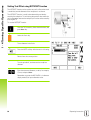
Setting tool offsets using TOOL/SET
The TOOL/SET operation can be used to set a tool’s offset using a tool
when the diameter of the workpiece is known.
Touch the known diameter in the X axis.
Press the TOOL hard key. Scroll to the desired tool.
Press the Enter key.
Select the axis (X) key.
Enter the position of the tool tip, for example,
X=Ø 20 mm.
Remember to ensure the ND 522/523 is in diameter
display mode (Ø) to input a diameter value.
Touch the workpiece face with the tool.
Cursor to the Z axis.
Set the position display for the tool tip to zero, Z=0.
Press Enter.
ND 522/523
59
I - 4 Turning Specific Operations
Setting Tool Offset using NOTE/SET Function
The NOTE/SET function can be used to set a tool’s offset when a tool
is under load, and the diameter of the workpiece is not known.
The NOTE/SET function is useful when determining tool data by
touching the workpiece. To avoid losing the position value when the
tool is retracted to measure the workpiece, this value can be stored by
pressing NOTE.
To use the NOTE/SET function:
Press the TOOL hard key. Select the desired tool, and
press Enter key.
Select the X axis key.
Turn a diameter in the X axis.
Press the NOTE soft key while the tool is still cutting.
Retract from the current position.
Turn the spindle off, and measure the workpiece
diameter.
Enter the measured diameter, or radius, for example,
15 mm, and press Enter.
Remember to ensure the ND 522/523 is in diameter
display mode (Ø) to input a diameter value.
60
I Operating Instructions
I - 4 Turning Specific Operations
Datum Hard key
See "Datum Hard key" on page 35 for basic information. Datum
settings define the relationships between the axis positions, and the
display values. For most lathe operations there is only one X-axis
datum, the center of the chuck, but it may be helpful to define
additional datums for the Z-axis. The table can hold up to 10 datum
points. The easiest way to set datum points is to touch a workpiece at
a known diameter, or location, then enter that dimension as the value
that the display should be showing
Example: Setting a workpiece datum.
Axis sequence in this example: X - Z
Preparation:
Call the tool data by selecting the tool which being used to touch the
workpiece.
Press the DATUM hard key.
The cursor will be in the DATUM NUMBER field.
Enter the datum number, and press the DOWN
ARROW key to go to the X AXIS field.
Touch the workpiece at point 1.
ND 522/523
61
I - 4 Turning Specific Operations
DATUM SETTING X
Enter the diameter of the workpiece at that point.
Remember to ensure the ND 522/523 is in diameter
display mode (Ø) to input a diameter value.
Press the DOWN ARROW key to advance to the Zaxis.
Touch the workpiece surface at point 2.
DATUM SETTING Z
Enter the position of the tool tip (Z = 0 mm) for the
Z-coordinate of the datum.
Press Enter.
62
I Operating Instructions
I - 4 Turning Specific Operations
Setting Datums using NOTE/SET Function
The NOTE/SET function is useful for setting a datum when a tool is
under load, and the diameter of the workpiece is not known.
To use the NOTE/SET function:
Press the DATUM hard key.
The cursor will be in the Datum Number field.
Enter the datum number, and press the DOWN
ARROW key to go to the X AXIS field.
Turn a diameter in the X axis.
Press the NOTE soft key while the tool is still cutting.
Retract from the current position.
Turn the spindle off, and measure the workpiece
diameter.
Enter the measured diameter, for example, 15 mm,
and press Enter.
Remember to ensure the ND 522/523 is in diameter
display mode (Ø) to input a diameter value.
ND 522/523
63
I - 4 Turning Specific Operations
Taper Calculator Hard Key
Calculate tapers either by entering dimensions from a print, or by
touching a tapered workpiece with a tool, or indicator.
Use the taper calculator to calculate taper angle.
Entry values:
For the taper ratio, calculation requires:
Change in the radius of the taper
Length of the taper
For taper calculations using both diameters (D1, D2), and length
requires:
Starting diameter
End diameter
Length of the taper
Press the CALC hard key.
The soft key selection has now changed, and includes
the taper calculator functions.
D1/D2 LENGTH
To calculate the taper angle using two diameters, and
length between, press the TAPER: D1/D2/L soft keys.
First taper point, DIAMETER 1, either enter a point
using the numeric keys, and press Enter, or touch the
tool to one point, and press NOTE.
Repeat this for the DIAMETER 2 field.
When using the NOTE key, the taper angle is
automatically calculated.
When entering data numerically, enter data into the
LENGTH field, and press Enter. The taper angle will
appear in the ANGLE field
TAPER RATIO
To calculate angles using the ratio of the diameter
change to length, press the TAPER: RATIO soft key.
Using the numeric keys, enter data into the ENTRY 1,
and ENTRY 2 fields. Press Enter after each selection.
The calculated ratio, and the angle will appear in their
respective fields.
64
I Operating Instructions
I - 4 Turning Specific Operations
Presetting
The Preset function has been explained previously in this manual (See
"Presetting" on page 39). The explanation, and examples on those
pages are based on a mill application. The basics of those explanations
are the same for turning applications with two exceptions; Tool
Diameter Offsets (R+/-), and Radius vs. Diameter inputs.
Tool diameter offsets have no applications with turning tools, so this
functionality is not available while doing turning presets.
While doing turning, input values can be either radius, or diameter
values. It is important to be sure the units being entered for the preset
agree with the state that the display is currently using. A diameter
value is shown with a Ø symbol. The state of the display can be
changed using the RX soft key (see below).
RX (Radius/Diameter) Soft Key
Drawings for lathe parts usually give diameter values. ND 522/523 can
display either the radius, or the diameter for you. When the diameter
is being displayed, the diameter symbol (Ø) is shown next to the
position value.
Example: Radius display, position 1 X = 20 mm
Diameter display, position 1 X = Ø 40 mm
Press the RX soft key to switch between radius
display, and diameter display.
ND 522/523
65
I - 4 Turning Specific Operations
Vectoring Hard Key
Vectoring breaks down the movement of the compound axis into the
crossfeed, or longitudinal axes. When turning threads, for example,
vectoring displays the diameter of the thread in the X-axis display,
even though the cutting tool is being moved with the compound axis
handwheel. With vectoring enabled, the desired radius can be preset,
or diameter in the X-axis, so that it is possible to “machine to zero”.
When vectoring is used, the top slide (compound) axis
encoder must be assigned to the bottom display axis. The
crossfeed component of movement of the axis will then be
shown in the top display axis. The longitudinal component
of movement of the axis will be shown in the middle display
axis.
Press the VECTORING hard key.
Press the ON soft key to enable the vectoring feature.
Arrow down to the Angle field to enter the angle between the
longitudinal slide, and top slide with 0° indicating the top slide is
moving parallel to the longitudinal slide. Press Enter.
66
I Operating Instructions
I - 4 Turning Specific Operations
Z Coupling (turning applications only)
The ND 522/523 Turning application provides a quick method for
coupling the Z0, and Z axis position on a 3 axis system. The display can
be coupled in either the Z, or Z0 displays.
Enabling Z Coupling
To couple the Z0, and Z axis, and have the result displayed on the Z0
display, press, and hold the Z0 key approximately 2 seconds. The sum
of the Z positions will be displayed on the Z0 display, and the Z display
will be blanked.
To couple the Z0, and Z axis, and have the result displayed on the Z
display, press, and hold the Z key for approximately 2 seconds. The
sum of the Z positions will be displayed on the Z display, and the Z0
display will be blanked. The coupling is preserved in between power
cycles.
Moving either Z0, or Z inputs will update the coupled Z position.
When a position is coupled, the reference mark for both encoders
must be found in order to recall the previous datum.
Disabling Z Coupling
To disable Z Coupling, press the axis key of the display that is blank.
The individual Z0, and Z display positions will be restored.
ND 522/523
67
68
I Operating Instructions
I - 4 Turning Specific Operations
Technical Information
II - 1 Installation, and Electrical Connection
II - 1 Installation, and Electrical
Connection
Items Supplied
ND 522/523 Display Unit
Power connector
Quick Reference Guide
Tilt / Swivel Assembly
Accessories
Mounting base
Assorted Mounting Arm assembilies
ND 522/523 Display Unit
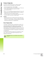
Mounting Location
Locate the unit in a well ventilated area such that it may be easily
accessed during normal operation.
Installation
A locking handle is used to secure the ND 522/523 from below on to
a mounting arm. The DRO mounting assembly comes complete with
swivel / tilt Kit: See "ND 522/523 Handle ID 618025-01" on page 89.
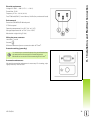
Electrical connection
There are no serviceable items within this unit. Therefore,
the ND 522/523 must never be opened.
The length of the power cord is not to exceed 3 meters.
Connect a protective ground to the protective conductor
terminal on the rear of the unit. This connection must never
be interrupted.
Do not engage, or disengage any connections while the
unit is under power. Damage to internal components may
result.
Use only original replacement fuses.
70
II Technical Information
II - 1 Installation, and Electrical Connection
Electrical requirements
Voltage AC 100 V ... 240 V (-15 % ... +10 %)
Power Max. 54 W
Frequency 47 Hz ... 63 Hz (±3 Hz)
FuseT 500 mA/250 V, 5 mm x 20 mm, Slo-Blo (line, and neutral fused)
Environmental
Protection (EN 60529) IP 40 back panel
IP 54 front panel
Operating temperature 0° to 45°C (32° to 113°F)
Storage temperature -20° to 70°C (-4° to 158°F)
Mechanical weight 2.6 kg (5.8 lb.)
Wiring the power connector
Hot leads: L, and N
Ground:
Minimum diameter of power connection cable: 0.75 mm2.
Protective earthing (grounding)
It is necessary to connect the protective ground terminal on
the rear panel to the star point of machine ground.
Minimum cross-section of the connecting wire: 6 mm2.
Preventative maintenance
No special preventative maintenance is necessary. For cleaning, wipe
lightly with a dry lint-free cloth.
ND 522/523
71
II - 1 Installation, and Electrical Connection
Connecting the Encoders
ND 522/523 can be used with HEIDENHAIN linear, and rotary
encoders that provide digital TTL level signals.
The connecting cable must not exceed 30 m (100 ft.) in length.
Do not engage, or disengage any connections while the
unit is under power.
Pin layout for encoder inputs.
D-sub connector
9-pin
Signal
1
/
2
Ua1
3
4
Ua2
5
6
0V
7
UP
8
Ua0
9
5
1
6
9
The operator can setup any encoder input to go to any axis.
Default configuration:
Encoder input
Mill
Turn
X1
X
X
X2
Y
Z0
X3
Z
Z
72
II Technical Information
II - 2 Installation Setup
II - 2 Installation Setup
Installation Setup Parameters
Installation setup is accessed by pressing the SETUP soft key, which
brings up INSTALLATION SETUP soft key.
Installation Setup parameters are established during the initial
installation and, most likely, will not often change. For this reason, the
installation setup parameters are protected by a passcode: (95148).
Type these digits in using the numeric key pad, and then press Enter.
Encoder Setup
The Encoder Setup form is used to set the encoder resolution, and
type (linear, rotary), count direction, reference mark type.
The cursor will default to the ENCODER SETUP field upon opening
Installation Setup. Press Enter. This opens a list of possible encoder
inputs.
Scroll to the encoder to be changed, and press Enter.
Cursor will be in the ENCODER TYPE field, select the encoder type
by pressing the LINEAR/ROTARY soft key.
For linear encoders, cursor to the RESOLUTION field, and use
COARSER, or FINER soft keys to select the encoder’s resolution in
µm (10, 5, 2, 1, 0.5), or type in the exact resolution. For rotary
encoders, enter the number of lines per revolution.
In the REFERENCE MARK field, toggling the REF MARK soft key
selects whether the encoder has no reference signal (NONE), single
reference mark (SINGLE), or (CODED) soft key.
For coded reference marks, press the SPACING soft key to select
500, 1000 or 2000 (LB 382C).
In the COUNT DIRECTION field, select the count direction by
pressing the POSITIVE, or NEGATIVE soft key. If the encoder’s
count direction matches the user’s count direction, select positive.
If the directions do not match, select negative.
In the ERROR MONITOR field, select whether the system will
monitor, and display encoder errors by selecting ON, or OFF. When
an error message occurs, press the C key to remove it.
ND 522/523
73
II - 2 Installation Setup
Display Configuration
The DISPLAY CONFIGURATION form is where the operator
determines which axes are displayed, and in what order.
Scroll to the desired display, and press Enter.
Press the ON/OFF soft key to turn the display on, or off. Press the
LEFT, or RIGHT ARROW key to select the axis label.
Scroll to the INPUT field.
Press 1, 2, or 3 to select the encoder input number (X1, X2, or X3).
Scroll to the DISPLAY RESOLUTION field. Press the COARSER, or
FINER soft keys to select the display resolution.
For rotory encoders, scroll to the angle display field. Press ANGLE
soft key to select the format for the angle display.
Coupling
Press the numeric keys associated with the encoder input on the
back of the unit. Press the +, or - soft keys to couple a second input
with the first. The input numbers are displayed next to the axis label
indicating that the position is a coupled position.
Error Compensation
The distance a cutting tool travels, measured by an encoder, can in
certain cases, differ from the actual tool travel. This error can occur
due to ball screw pitch error, or deflection, and tilting of axes. This
error can either be linear, or non-linear. These errors can be
determined with a reference measurement system, e.g. the VM 101
from HEIDENHAIN, or with gauge blocks. From an analysis of the error
it can be determined which form of compensation is required, linear,
or non-linear error.
The ND 522/523 provides the opportunity to compensate for these
errors, and each axis can be programmed separately with the
appropriate compensation.
Error compensation is only available when using linear
encoders.
74
II Technical Information
II - 2 Installation Setup
Linear Error Compensation
Linear error compensation can be applied, if the results of the
comparison with a reference standard show a linear deviation over the
whole measuring length. In this case the error can be compensated by
the calculation of a single correction factor.
To calculate the linear error compensation use this formula:
Correction factor LEC = ((S – M) /M) x 106 ppm with:
measured length with reference standard
measured length with device at axis
S
M
Example:
If the length of the standard used is 500 mm, and the measured length
along the X-axis is 499.95, then the LEC for the X-axis is
100 parts per million (ppm).
LEC = ((500 – 499.95) / 499.95) x 106 ppm = 100 ppm (rounded to
the nearest whole number).
Once determined, the encoder’s error information is entered
directly. Press the TYPE soft key to select LINEAR compensation.
Enter the compensation factor in parts per million (ppm), and press
the Enter key.
Non-Linear Error Compensation
Non-linear error compensation should be applied, if the results of the
comparison with a reference standard show an alternating, or
oscillating deviation. The required correction values are calculated, and
entered in a table. ND 522/523 supports up to 200 points per axis. The
error value between two entered adjacent correction points is
calculated with linear interpolation.
Non-linear error compensation is only available on scales
with reference marks. If non-linear error compensation has
been defined, no error compensation will be applied until
the reference marks have been crossed.
Starting a Non-linear Error Compensation Table
Select Non-linear by pressing the TYPE soft key.
To start a new error compensation table, first press the EDIT TABLE
soft key. Press enter.
All correction points (up to 200) are equally spaced from the start
point. Enter the distance between each of the correction points.
Press the DOWN ARROW key.
Enter the table’s start point. The start point is measured from the
scale’s reference point. If this distance is not known, move to the
location of the start point, and press TEACH POSITION. Press
Enter.
ND 522/523
75
II - 2 Installation Setup
Configuring the Compensation Table
Press the EDIT TABLE soft key to view the table entries.
Use the UP, or DOWN ARROW keys, or the numeric keys to move
the cursor to the correction point to be added, or changed. Press
Enter.
Enter the known error which exists at this point. Press Enter.
When completed, press C key to exit the table, and return to the
ERROR COMPENSATION form.
Pressing Enter saves the Error Compensation data
entered, and is retained if the power is cycled. Pressing the
C key to exit without pressing the Enter key only retains
data until power is cycled.
Reading the Graph
The error compensation table may be viewed in table, or graphical
formats. The graph shows a plot of a translation error vs. measured
value. The graph has a fixed scale. As the cursor is moved through the
form, the location of the point on the graph is indicated with a vertical
line.
Viewing the Compensation Table
Press the EDIT TABLE soft key.
To switch between the table, and graph views, press the VIEW soft
key.
Press the UP, or DOWN ARROW keys, or the numeric keys to move
the cursor within the table.
The error compensation table data may be saved to, or loaded from a
PC via the USB port.
Exporting the Current Compensation Table
Press the EDIT TABLE soft key
Press the IMPORT/EXPORT soft key.
Press the EXPORT TABLE soft key.
Importing a New Compensation Table
Press the EDIT TABLE soft key.
Press the IMPORT/EXPORT soft key.
Press the IMPORT TABLE soft key.
76
II Technical Information
II - 2 Installation Setup
Backlash Compensation
When using a rotary encoder with a lead screw, a change in direction
of the table might cause an error in the displayed position due to
clearances within the lead screw assembly. This clearance is referred
to as backlash. This error can be compensated for by inputting the
amount of backlash within the lead screw into the Backlash
Compensation feature.
If the rotary encoder is ahead of the table (displayed value is greater
than the table’s true position), this is called positive backlash, and the
value entered should be the positive value of the amount of error.
No Backlash Compensation is 0.000.
ND 522/523
77
II - 2 Installation Setup
Counter Settings
The COUNTER SETTINGS form is the parameter where the operator
defines the user application for the readout. The choices are for
milling, or turning applications.
A FACTORY DEFAULT soft key appears in the COUNTER SETTINGS
choice of options. When pressed, the configuration parameters (based
on either mill, or turn) will be reset to factory defaults. The operator will
be prompted to press YES to set parameters to factory default
settings, or NO to cancel, and return to previous menu screen.
The NUMBER OF AXES field sets the number of axes needed. An
axes soft key will appear to choose between either 2, or 3 axes.
Diagnostics
The DIAGNOSTICS form provides access for testing the keypad, and
display.
Keypad Test
An image of the keypad provides an indication when a switch is
pressed, and released.
Press each hard, and soft key to test. A dot will appear on each key
when it has been pressed indicating that it is operating properly.
Press the C key two times to exit the keypad test.
Display Test
To test the display, press the enter key to set the display to solid
black, solid white, and then back to normal.
78
II Technical Information
II - 3 Encoder Parameters
II - 3 Encoder Parameters
The following tables represent a partial list of encoders. These tables
describe all operating parameters that must be set for the encoders.
Most entries can be found in the operating instructions for that
encoder.
Example settings for HEIDENHAIN linear encoders
Encoder
Signal period
Reference marks
LS 328C
LS 628C
5µm
Single/1000
LB 382 with
IBV 101
1µm
Single
LB 382C with
IBV 101
1µm
Single/2000
LS 378C
LS 678C
1µm
Single/1000
Example settings for HEIDENHAIN Rotary encoders
Rotary
Encoders
Line Count
Resolution
Reference
mark
ROD 420
50 to 5000
1.8° to 64.8 arc sec
single
ROD 426
50 to 10000
1.8° to 32.4 arc sec
single
ROD 1020
250 to 3600
.36° to 90 arc sec
single
ROD 1070
1000 to 3600
32.4 to 9 arc sec
single
ERN 120
1000 to 5000
324 to 64.8 arc sec
single
ERN 420
250 to 5000
.36° to 64.8 arc sec
single
ERN 1020
250 to 3600
.36° to 90 arc sec
single
ERN 1070
1000 to 3600
32.4 to 9 arc sec
single
Example settings for HEIDENHAIN Angle encoders
Angle
Encoders
Line Count
Resolution
Reference
mark
ROD 225
9000, or 10000
36 to 18 arc sec
single
ROD 275
18000
3.6 to 1.8 arc sec
single
ND 522/523
79
II - 4 Data Interface
II - 4 Data Interface
The ND 522/523's data interface includes the USB port. The USB port
supports both bi-directional data communications which allows data to
be exported to, or imported from an external device, and external
operations via the data interface.
Data which can be exported from the ND 522/523 to an external serial
device includes:
Job, and installation configuration parameters
Non-linear error compensation tables
Data which can be imported into ND 522/523 from an external device
includes:
Remote key commands from an external device
Job, and installation configuration parameters
Non-linear error compensation tables
This chapter covers information about setting up the data interface:
80
II Technical Information
II - 4 Data Interface
USB Port (type “B”)
The USB port is located on the rear panel. The following device can be
connected to this port:
Personal computer with serial data interface
For operations that support data transfer, an IMPORT/EXPORT soft
key will be available.
To export, or import data between the ND 522/523, and a personal
computer, the PC must use terminal communications software such
as TNC Remo. (TNC Remo is available for free at:
http://filebase.heidenhain.de/doku/english/serv_0.htm. Contact a
Heidenhain distributor for further details.) This software processes the
data being sent, or received over the serial cable link. All data
transferred between ND 522/523, and the PC is in ASCII text format.
To export data from the ND 522/523 to a PC, the PC must first be
made ready to receive the data to save it to a file. Setup the terminal
communication program to capture ASCII text data from the COM port
to a file on the PC. After the PC is ready to receive, start the data
transfer by pressing the ND 522/523’s IMPORT/EXPORT soft key.
Select Export.
To import data into the ND 522/523 from a PC, the ND 522/523 must
first be made ready to receive the data. Press the ND 522/523’s
IMPORT/EXPORT soft key. Select Import. After the ND 522/523 is
ready, setup the terminal communications program on the PC to send
the desired file in ASCII text format.
Data format
Data is transferred in the following sequence:
The ND 522/523 does not support communication
protocols such as Kermit, or Xmodem.
External Operations via USB port
The display unit can be operated over the USB port data interface
using an external device. The following key commands are available:
Format
<ESC>TXXXX<CR>
Key is pressed
Sequence of commands
Function
<ESC>T9000<CR>
Key ‘0’
<ESC>T9001<CR>
Key ‘1’
<ESC>T9002<CR>
Key ‘2’
<ESC>T9003<CR>
Key ‘3’
<ESC>T9004<CR>
Key ‘4’
<ESC>T9005<CR>
Key ‘5’
ND 522/523
81
II - 4 Data Interface
Sequence of commands
Function
<ESC>T9006<CR>
Key ‘6’
<ESC>T9007<CR>
Key ‘7’
<ESC>T9008<CR>
Key ‘8’
<ESC>T9009<CR>
Key ‘9’
<ESC>T9010<CR>
Key ‘CE’, or ‘CL’
<ESC>T9011<CR>
Key ‘.’
<ESC>T9012<CR>
Key ‘Enter’
<ESC>T9013<CR>
Key ‘X’
<ESC>T9014<CR>
Key ‘Y’/’Z’/’Z0’
<ESC>T9015<CR>
Key ‘Z’
<ESC>T9016<CR>
Key ‘Soft key 1’
<ESC>T9017<CR>
Key ‘Soft key 2’
<ESC>T9018<CR>
Key ‘Soft key 3’
<ESC>T9019<CR>
Key ‘Soft key 4’
<ESC>T9020<CR>
Key ‘Cursor Left’
<ESC>T9021<CR>
Key ‘Cursor Right’
<ESC>T9022<CR>
Key ‘Cursor Up’
<ESC>T9023<CR>
Key ‘Cursor Down’
<ESC>T9024<CR>
Key ‘+’
<ESC>T9025<CR>
Key ‘-’
<ESC>T9026<CR>
Key ‘x’
<ESC>T9027<CR>
Key ‘/’
<ESC>T9028<CR>
Key ‘Square Root’
<ESC>T9029<CR>
Key ‘Pi’
<ESC>T9030<CR>
Key ‘INC/ABS’
<ESC>T9031<CR>
Key ‘1/2’
<ESC>T9032<CR>
Key ‘Calc’
<ESC>T9033<CR>
Key ‘Datum’
<ESC>T9034<CR>
Key ‘Tool’
82
II Technical Information
Function
<ESC>T9035<CR>
Key ‘Circle Pattern’
<ESC>T9036<CR>
Key ‘Linear Pattern’
<ESC>T9037<CR>
Key ‘Incline Milling’/’Vectoring’
<ESC>T9038<CR>
Key ‘Arc Mill/Taper Calc’
ND 522/523
II - 4 Data Interface
Sequence of commands
83
II - 5 Measured Value Output
II - 5 Measured Value Output
Examples of character output at the data
interface
A PC can be used to retrieve values from ND 522/523. In all three
examples, measured value output is started with Ctrl B (sent over
USB interface). Ctrl B will transmit the currently displayed values in
either Incremental, or Absolute mode, whichever is currently visible.
Example 1: Linear axis with radius display X = + 41.29 mm
X
=
+
41
.
29
1
2
3
4
5
6
7
R
<CR>
<LF>
8
9
10
1 Coordinate axis
2 Equal sign
3 +/– sign
4 2 to 7 places before the decimal point
5 Decimal point
6 1 to 6 places after the decimal point
7 Unit: blank space for mm, “ for inches
8 Absolute display:
R for radius, D for diameter
Distance-to-go display:
r for radius, d for diameter
9 Carriage return
10 Blank line (Line Feed)
84
II Technical Information
C
=
+
1260
.
0000
1
2
3
4
5
6
7
W <CR>
<LF>
8
10
9
II - 5 Measured Value Output
Example 2: Rotary axis with degrees decimal display
C = + 1260.0000°
1 Coordinate axis
2 Equal sign
3 +/– sign
4 4 to 8 places before the decimal point
5 Decimal point
6 0 to 4 places after the decimal point
7 Blank space
8 W for angle (in distance-to-go display: w)
9 Carriage return
10 Blank line (Line Feed)
Example 3: Rotary axis with degrees/minutes/seconds display
C = + 360° 23' 45'' '
C
=
+
360
:
23
:
45
1
2
3
4
5
6
7
8
9
W
<CR>
<LF>
10
11
12
1 Coordinate axis
2 Equal sign
3 +/– sign
4 3 to 8 places degrees
5 Colon
6 0 to 2 places minutes
7 Colon
8 0 to 2 places seconds
9 Blank space
10 W for angle (in distance-to-go display: w)
11 Carriage return
12 Blank line (Line Feed)
ND 522/523
85
II - 6 Specifications for Milling
II - 6 Specifications for Milling
ND 522/523 Data
Axes
2, or 3 axes from A - Z, 0-9
Encoder inputs
Digital TTL Signal levels; input frequency max. 100 kHz
for incremental HEIDENHAIN encoders
Display step
Linear axes: 1 mm to 0.1 µm
Rotary axes: 1° to 0.0001° (00°00’01”)
Display
Monochrome display for position values, dialogue, and input display, graphic
functions, graphic positioning aid
Status display:
Operating mode, REF, inch/mm, scaling factor, feed rate, stop watch
Datum number
Tool number
Tool compensation R–, R+
Functions
REF reference-mark evaluation for distance-coded, or single reference marks
Distance-to-go mode, nominal position input (Incremental, or Absolute )
Scaling factor
HELP: On-screen operating instructions
INFO: Calculator, cutting data calculator, user, and operating parameters
10 datum points, and 16 tools
Tool radius compensation
Calculation of positions for bolt hole circles, and linear hole patterns
Error compensation
Linear, and non-linear, up to 200 measuring points
Backlash compensation
Rotary encoder applications with ballscrews
Data interface
USB (type B connector) 115 200 baud
For output of measured values, and parameters;
For input of parameters, and remote keys
Accessories
Mounting Base
Universal Mounting Arm Kits
Main power input
AC 100 V ... 240 V (-15 % ... +10 %); 47 Hz ... 63 Hz (±3 Hz);
power consumption max. 54 W
Operating temperature
0°C to 45°C (32 °F to 113 °F)
Storage temperature
-20°C to 70°C (-4°F to 158°F)
Degree of protection (EN 60529)
IP 40 (IP 54 front panel)
Weight
2.6 kg
86
II Technical Information
II - 7 Specifications for Turning
II - 7 Specifications for Turning
ND 522/523 Data
Axes
2, or 3 axes from A to Z, Z0, 0-9
Encoder inputs
Digital TTL Signal levels; input frequency max. 100 kHz for incremental
HEIDENHAIN encoders
Display step
Linear axes: 1 mm to 0.1 µm
Rotary axes: 1° to 0.0001° (00°00’01”)
Display
Monochrome display for position values, dialogue, and input display, graphic
functions, graphic positioning aid
Status display:
tool number, operating mode, REF, inch/mm, scaling factor, feed rate,
diameter display Ø, stop watch, datum
Functions
REF reference-mark evaluation for distance-coded, or single reference marks
Distance-to-go mode, nominal position input (Incremental, or Absolute )
Scaling factor
HELP: On-screen operating instructions
INFO: Calculator, taper calculator, user, and operating parameters
10 datum point, 16 tools
Freezing tool position for back-off
Backlash Compensation
Rotary encoder applications with ballscrews
Error Compensation
Linear, and non-linear, up to 200 measuring points
Data interface
USB (type B connector) 115 200 baud
For output of measured values, and parameters;
For input of parameters, remote keys, and commands
Accessories
Mounting Base
Universal Mounting Arm Kits
Main power input
AC 100 V ... 240 V (-15 % ... +10 %); 47 Hz ... 63 Hz (±3 Hz);
power consumption max. 54 W
Operating temperature
0°C to 45°C (32 °F to 113 °F)
Storage temperature
-20°C to 70°C (-4°F to 158°F)
Degree of protection (EN 60529)
IP 40 (IP 54 front panel)
Weight
2.6 kg
ND 522/523
87
II - 8 Dimensions
II - 8 Dimensions
Dimensions mm/inches
Front view with Dimensions
Back view
Bottom view with Dimensions
88
II Technical Information
II - 9 Accessories
II - 9 Accessories
Accessory ID Numbers
ID Number
Accessories
532522-01
Pkgd, ND 522
532523-01
Pkgd, ND 523
625491-01
Pkgd, Mounting Base ND 522/523
ND 522/523 Handle
ID 618025-01
DRO mounting with arm (reference information)
Mounting bolt
Tilt / Swivel Clamp
Read out
mounting
arm options
(not included)
Handle
Lock nut
The DRO mounting base has a slot feature that prevents
the lock nut from turning. Pre-assemble all components to
the mounting arm. Then slip the DRO on to the clamp.
Secure the DRO into position by tightening the handle.
ND 522/523
89
II - 9 Accessories
DRO mounting with arm (reference information
DRO mounting Base
option (not included)
Lock nut
(included with DRO)
Hand Locking Bolt
Tilt / Swivel Clamp
(included with DRO)
The DRO mounting base accessory typically mounts to a
flat surface on the machine. The mounting hardware
assembly attaches to the DRO in the same fashion as the
Handle assembly (which is included with the DRO).
90
II Technical Information
E
L
1/2 soft key ... 29
Electrical Connection ... 70
Electrical Requirements ... 71
Enable Ref soft key ... 21
Enable/Disable Ref Function ... 22
Encoder Parameters ... 79
Encoder Setup ... 73
Enter Key ... 18
Environmental specs. ... 71
Error Compensation ... 74
Error Messages ... 20
Language (setting) ... 26
Left/Right arrow keys ... 18
Linear Error Compensation ... 75
Linear Pattern ... 49, 52
A
Absolute coordinates ... 13
Absolute datum ... 12
Absolute Distance Preset ... 39
Absolute Workpiece Positions ... 13
Accessories ... 89
Actual Value/Distance-To-Go soft
key ... 18
Arc Milling ... 55
Axis Labels ... 16
B
Backlash Compensation ... 77
C
C (Clear) Key ... 18
Calc soft key ... 30
Centerline between two probed edges
as datum ... 37
Circle Pattern ... 46
Connecting Cable ... 72
Connecting the Encoders ... 72
Console adjustment ... 26
Counter Settings ... 67, 78
D
Data Input Forms ... 20
Data Interface ... 80
Datum setting without probing
function ... 33, 36, 61
Datum soft key ... 35
Datum Soft Key (Turning) ... 61
Datums ... 12
Diagnostics ... 78
Diameter Axes (Turning) ... 24
Dimensions ... 88
Disable Ref soft key ... 22
Display Area ... 16
Display configuration ... 74
distance-coded reference marks ... 15
F
fixed reference marks ... 15
Fundamentals of Positioning ... 12
G
General Navigation ... 18
General Operation’s Soft Key Function
Detailed ... 28
General Operation’s Soft Key Function
Overview ... 17, 27
Graphic Positioning Aid ... 19
Graphic Positioning Aid (setting) ... 25
H
Handle ... 89
Help Screen ... 19
I
Import/Export (setting) ... 26, 31
Inch/MM soft key ... 23
Incremental coordinates ... 13
Incremental Distance Preset ... 43
Incremental Workpiece Positions ... 13
Index soft key ... 19
Installation Setup Parameters ... 73
Instruction Box ... 20
Items Supplied ... 70
J
Job Setup menu ... 23
Job Setup Parameters ... 23
K
Keypad, use ... 18
ND 522/523
Index
SYMBOLE
M
Measured Value Output ... 84
Milling Specific Operations and Soft Key
Functions Detailed ... 31
Mirror ... 24
Mounting Instructions for Mounting
Arm ... 89
Mounting Location ... 70
N
No Ref soft key ... 21
Non-Linear Error Compensation ... 75
O
Operating Modes ... 18
P
Patterns (Milling) ... 46
Position Encoders ... 14
Position feedback ... 14
Power Up ... 21
Preset ... 39
Preset Soft Key (Turning) ... 65
Preventative Maintenance ... 71
Protective earthing (grounding) ... 71
R
Radius/Diameter display ... 65
REF ... 14
Ref Symbols ... 16
Reference Mark Evaluation ... 21
Reference marks ... 15
crossing over ... 21
S
Scale factor ... 24
Screen Layout ... 16
Set Zero soft key ... 28
Setup ... 23
Setup soft key ... 23
Soft key Labels ... 16
Specs. for Milling ... 86
Specs. for Turning ... 87
Status Bar (setting) ... 25
Stopwatch (setting) ... 25
91
Index
T
Taper calculator ... 64
Tool call ... 35
Tool setting, turning ... 59
Tool soft key ... 32
Tool soft key (Turning) ... 58
Tool Table Usage ... 33
Tool Table Usage (Turning) ... 59
U
Units of measurement, setting ... 23
Up/Down arrow keys ... 18
V
Vectoring ... 66
W
Working without reference mark
evaluation ... 21
Z
Z Coupling ... 67
Zero Angle Reference Axis ... 14
92
DR. JOHANNES HEIDENHAIN GmbH
Dr.-Johannes-Heidenhain-Straße 5
83301 Traunreut, Germany
{ +49 8669 31-0
| +49 8669 5061
E-mail: [email protected]
www.heidenhain.de
606084-23 · Ver03 · PDF · 7/2014