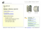
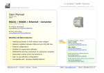
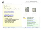
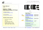
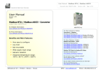
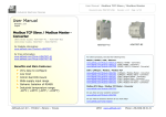
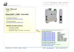
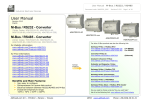
1
User Manual
CAN / Ethernet - Converter
Document code: MN67513_ENG
Revision 2.002
Page 1 of 17
Industrial Electronic Devices
User Manual
Revision 2.002
English
CAN / Ethernet - Converter
(Order Code: HD67513-A1 – HD67513-B2)
for Website information:
www.adfweb.com?Product=HD67513
HD67513
HD67513
HD67513-A1
for Price information:
www.adfweb.com?Price=HD67513-A1
www.adfweb.com?Price=HD67513-B2
For others Gateway / Adapter:
Ethernet to
Benefits and Main Features:
Mountable on Rail DIN
TCP/UDP protocols changeable with software
Easy to use software configuration
Industrial temperature range:
-40 °C / 85°C (-40°F / 185°F)
HD67513-B2
Similiar
Products
See also the following link:
www.adfweb.com?Product=HD67213
www.adfweb.com?Product=HD67503
www.adfweb.com?Product=HD67506
www.adfweb.com?Product=HD67563M
(J1939)
(CANopen)
(Modbus RTU)
(PROFIBUS)
For others Converter / Adapter:
RS232 to RS485
See also the following link:
www.adfweb.com?Product=HD67118
USB to RS485
See also the following link:
www.adfweb.com?Product=HD67119
Do you have an your customer protocol?
See the following link:
www.adfweb.com?Product=HD67003
Do you need to choose a device? do you want help?
Ask it to the following link:
www.adfweb.com?Cmd=helpme
ADFweb.com Srl – IT31010 – Mareno – Treviso
INFO: www.adfweb.com
Phone +39.0438.30.91.31
User Manual
CAN / Ethernet - Converter
Document code: MN67513_ENG
Revision 2.002
Page 2 of 17
Industrial Electronic Devices
INDEX:
INDEX
UPDATED DOCUMENTATION
REVISION LIST
WARNING
TRADEMARKS
SECURITY ALERT
CONNECTION SCHEME
POWER SUPPLY
CHARACTERISTICS
CONFUGURATION
USE OF COMPOSITOR SW67513
NEW PROJECT / OPEN PROJECT
SET COMMUNICATION
PING DEVICE
RECEIVE COB
UPDATE VIA SERIAL
CHARACTERISTICS OF THE CABLES
ETHERNET PROTOCOL
Write Frames
Read Frames
MECHANICAL DIMENSIONS
ORDER CODE
ACCESSORIES
DISCLAIMER
OTHER REGULATIONS AND STANDARDS
WARRANTIES AND TECHNICAL SUPPORT
RETURN POLICY
PRODUCTS AND RELATED DOCUMENTS
UPDATED DOCUMENTATION:
Page
2
2
2
2
2
3
4
6
7
7
7
8
9
9
10
11
12
13
13
14
15
15
15
16
16
17
17
17
Dear customer, we thank you for your attention and we remind you that you
need to check that the following document is:
Updated
Related to the product you own
To obtain the most recently updated document, note the “document code” that
appears at the top right-hand corner of each page of this document.
With this “Document Code” go to web page www.adfweb.com/download/ and
search for the corresponding code on the page. Click on the proper “Document
Code” and download the updates.
To obtain the updated documentation for the product that you own, note the
“Document Code” (Abbreviated written "Doc. Code" on the label on the product)
and download the updated from our web site www.adfweb.com/download/
REVISION LIST:
Revision
1.001
1.002
1.003
2.000
2.002
Date
20/01/2009
07/05/2010
30/09/2010
10/11/2011
24/01/2013
Author
Fl
Ml , Dp
Fl
Fl
Nt
Chapter
All
All
All
All
All
Description
Software changed
Revision
Revision
Codes changed
Added new chapters
WARNING:
ADFweb.com reserves the right to change information in this manual about our
product without warning.
ADFweb.com is not responsible for any error this manual may contain.
TRADEMARKS:
All trademarks mentioned in this document belong to their respective owners.
ADFweb.com Srl – IT31010 – Mareno – Treviso
INFO: www.adfweb.com
Phone +39.0438.30.91.31
User Manual
CAN / Ethernet - Converter
Document code: MN67513_ENG
Revision 2.002
Page 3 of 17
Industrial Electronic Devices
SECURITY ALERT:
GENERAL INFORMATION
To ensure safe operation, the device must be operated according to the instructions in the manual. When using the device are required for each
individual application, legal and safety regulation. The same applies also when using accessories.
INTENDED USE
Machines and systems must be designed so the faulty conditions do not lead to a dangerous situation for the operator (i.e. independent limit
switches, mechanical interlocks, etc.).
QUALIFIED PERSONNEL
The device can be used only by qualified personnel, strictly in accordance with the specifications.
Qualified personnel are persons who are familiar with the installation, assembly, commissioning and operation of this equipment and who have
appropriate qualifications for their job.
RESIDUAL RISKS
The device is state of the art and is safe. The instrument can represent a potential hazard if they are inappropriately installed and operated by
personnel untrained. These instructions refer to residual risks with the following symbol:
This symbol indicates that non-observance of the safety instructions is danger for people to serious injury or death and / or the possibility
of damage.
CE CONFORMITY
The declaration is made by us. You can send an email to [email protected] or give us a call if you need it.
ADFweb.com Srl – IT31010 – Mareno – Treviso
INFO: www.adfweb.com
Phone +39.0438.30.91.31
User Manual
CAN / Ethernet - Converter
Document code: MN67513_ENG
Revision 2.002
Page 4 of 17
Industrial Electronic Devices
CONNECTION SCHEME:
Figure 1: Connection scheme HD67513-A1
ADFweb.com Srl – IT31010 – Mareno – Treviso
INFO: www.adfweb.com
Phone +39.0438.30.91.31
User Manual
CAN / Ethernet - Converter
Document code: MN67513_ENG
Revision 2.002
Page 5 of 17
Industrial Electronic Devices
Figure 2: Connection scheme for HD67513-B2
ADFweb.com Srl – IT31010 – Mareno – Treviso
INFO: www.adfweb.com
Phone +39.0438.30.91.31
User Manual
CAN / Ethernet - Converter
Document code: MN67513_ENG
Revision 2.002
Page 6 of 17
Industrial Electronic Devices
POWER SUPPLY:
The devices can be powered at 8…19V AC and 8…35V DC. The consumption depends to the code of the device. For more details see the two
tables below.
VAC
VDC
Vmin
Vmax
Vmin
Vmax
8V
19V
8V
35V
Consumption at 24V DC:
Device
Consumption [W/VA]
HD67513-A1
4
HD67513-B2
5
Caution: Not reverse the polarity power
HD67513-A1
ADFweb.com Srl – IT31010 – Mareno – Treviso
HD67513-B2
INFO: www.adfweb.com
Phone +39.0438.30.91.31
User Manual
CAN / Ethernet - Converter
Document code: MN67513_ENG
Revision 2.002
Page 7 of 17
Industrial Electronic Devices
CHARACTERISTICS:
The Configurable CAN / Ethernet - Converter allows the following characteristics:
TCP/UDP Ethernet protocols changeable with software;
Mountable on Rail DIN;
Temperature range -40°C to 85°C.
This device is able to manage a maximum of four simultaneous connections from Ethernet side.
CONFIGURATION:
You need Compositor SW67513 software on your PC in order to perform the following:
Define the parameter of the CAN bus;
Define the parameter of the Ethernet;
Define a list of Receive COB.
USE OF COMPOSITOR SW67513:
To configure the Gateway, use the available software that runs
with Windows, called SW67513. It is downloadable on the site
www.adfweb.com and its operation is described in this document.
When launching the SW67513 the right window appears (Fig. 3).
Figure 3: Main window for SW67513
ADFweb.com Srl – IT31010 – Mareno – Treviso
INFO: www.adfweb.com
Phone +39.0438.30.91.31
User Manual
CAN / Ethernet - Converter
Document code: MN67513_ENG
Revision 2.002
Page 8 of 17
Industrial Electronic Devices
NEW PROJECT / OPEN PROJECT:
The “New Project” button creates the folder which contains the entire device configuration.
A device configuration can also be imported or exported:
To clone the configurations of a Programmable CAN to Ethernet Gateway in order to configure another device in the same manner,
it is necessary to maintain the folder and all its contents;
To clone a project in order to obtain a different version of the project, it is sufficient to duplicate the project folder with another name
and open the new folder with the button “Open Project”;
When a new project is created or an existent project is open, it will be possible to access the various configuration sections of the
Software.
ADFweb.com Srl – IT31010 – Mareno – Treviso
INFO: www.adfweb.com
Phone +39.0438.30.91.31
User Manual
CAN / Ethernet - Converter
Document code: MN67513_ENG
Revision 2.002
Page 9 of 17
Industrial Electronic Devices
SET COMMUNICATION:
This section define the fundamental communication parameter of two buses, CAN Bus and Ethernet.
By pressing the “Set Communication” button from the main window for SW67513 (Fig. 3) the window
“Set Communication” appears (Fig. 4).
The window is divided in two sections, one for the CAN Bus and the other for the Ethernet.
The means of the fields for “CAN Bus” are:
In the field “Baud rate” the baudrate for the CAN Bus is defined;
If the field “CAN Bus 2.0A” is checked, the CAN with a CobID of 11Bit is used; otherwise if the
field “CAN Bus 2.0B” is checked, the CAN with a CobID of 29Bit is used.
The means of the fields for “Ethernet” are:
In the field “IP ADDRESS” insert the IP address;
In the field “SUBNET Mask” insert the SubNet Mask;
In the field “Port” insert the number of the port;
If the field “TCP” is checked the Ethernet protocol used is the TCP, otherwise if the field “UDP”
is checked the Ethernet protocol used is the UDP.
Figure 4: “Set Communication” window
PING DEVICE:
If it is necessary to do a Ping on the net, before pressing the “Ping Device” button insert a value in the field on the right and then press the
button. In order to do this, the gateway must be in RUN mode. To use this feature in Vista and 7 you have to open the software with
Administrator right.
ADFweb.com Srl – IT31010 – Mareno – Treviso
INFO: www.adfweb.com
Phone +39.0438.30.91.31
User Manual
CAN / Ethernet - Converter
Document code: MN67513_ENG
Revision 2.002
Page 10 of 17
Industrial Electronic Devices
RECEIVE COB:
By pressing the “Receive COB” button from the main window for SW67513
(Fig. 3) the window “Receive CAN Frame” appears (Fig. 5).
The means of the fields are:
In the field “CobID” insert the Cob_ID of the CAN Bus frame;
In the field “Dimension” insert the number of bytes of CAN Bus
frame (the maximum dimensions is 8 bytes);
In the field “Mnemonic” you can insert a brief description.
Figure 5: “Receive CAN Frame” window
ADFweb.com Srl – IT31010 – Mareno – Treviso
INFO: www.adfweb.com
Phone +39.0438.30.91.31
User Manual
CAN / Ethernet - Converter
Document code: MN67513_ENG
Revision 2.002
Page 11 of 17
Industrial Electronic Devices
UPDATE VIA SERIAL
Section “Update Via Serial” (Fig. 6):
In order to load the parameters or update the firmware in the
gateway, follow these instructions:
Turn OFF the device;
Connect the Null Modem cable from your PC to the Gateway;
Insert the Boot Jumper (For more info see the “Connection
scheme” of the gateway);
Turn ON the device;
Check the “BOOT Led”. It must blink quickly (more info see the
“Connection scheme” of the gateway);
Select the COM port and press the “Connect” button;
Press the “Next” button;
Select the operations you want to do. You can select only “Firmware”,
only “Project” or both of them;
Press the “Execute update firmware” button to start the upload;
When all the operations are “OK” turn OFF the device;
Disconnect the Boot Jumper;
Turn ON the device.
At this point the configuration/firmware on the device is correctly updated.
Figure 6: “Update Via Serial” windows
ADFweb.com Srl – IT31010 – Mareno – Treviso
INFO: www.adfweb.com
Phone +39.0438.30.91.31
User Manual
CAN / Ethernet - Converter
Document code: MN67513_ENG
Revision 2.002
Page 12 of 17
Industrial Electronic Devices
CHARACTERISTICS OF THE CABLES:
The connection with Ethernet socket must be with a Ethernet Cable with a RJ45 Plug.
The connection from RS232 socket to a serial port (example one from a personal computer) must be made with a Null Modem cable (a
serial cable where the pins 2 and 3 are crossed).
It is recommended that the RS232C Cable not exceed 15 meters.
Figure 7: Null modem cabling
ADFweb.com Srl – IT31010 – Mareno – Treviso
INFO: www.adfweb.com
Phone +39.0438.30.91.31
User Manual
CAN / Ethernet - Converter
Document code: MN67513_ENG
Revision 2.002
Page 13 of 17
Industrial Electronic Devices
ETHERNET PROTOCOL
This protocol is able to read and write frames in the CAN net.
Write Frames
The transmission is very simple; it requires only what are the packets to send. In a single request it is possible to write at maximum 19 frames
in the CAN net. The Bytes that composed the request are these:
Byte Number
1
2
3÷6
7
8÷15
Description
Write Identifier (0x02)
Number of frames to send
Cob_ID
Number of Byte to send (0x01÷0x08)
Data (Byte 8 is the higher, byte 15 is the lower)
A single frame is composed by 13 bytes (byte 3 to byte 15). If the “Number of frame to send” (Byte Number 2) has got a value greater than
zero, the next frame is composed from byte 3 to byte 15 and so for all the frames.
If the “Number of Byte to send” has got a value less than 0x08 the byte of Data unused must be put with value 0x00.
The response is composed only by one byte. It can have two values:
• 0x00: No Errors;
• 0x01: Parameter Error.
Example:
We want to write three frames with the following characteristics:
Frame 1: Cob_ID=0x0000018A; Number of Byte to send=8; Data=0x0102030405060708;
Frame 2: Cob_ID=0x000413CB; Number of Byte to send=6; Data=0x1122334455660000;
Frame 3: Cob_ID=0x00000001; Number of Byte to send=8; Data=0x123456789A9B9C9D.
So the string of hexadecimal numbers is:
REQ:[02][03][00][00][01][8A][08][01][02][03][04][05][06][07][08][00][04][13][CB][06][11][22][33][44][55][66][00][00][00][00][00][01]
[08][12][34][56][78][9A][9B][9C][9D]
RES:[00]
ADFweb.com Srl – IT31010 – Mareno – Treviso
INFO: www.adfweb.com
Phone +39.0438.30.91.31
User Manual
CAN / Ethernet - Converter
Document code: MN67513_ENG
Revision 2.002
Page 14 of 17
Industrial Electronic Devices
Read Frames
For reading Data it is necessary to have a map in the RAM memory that contains the Data that passing in the bus. This map is implemented in
the “Compositor SW67513” but it has some standard addresses given by the software. It is possible to see this map in Fig. 5.
The Bytes that composed the request are these:
Byte Number
1
2
3
4
5
Description
Read Identifier (0x01)
Starting Address Hi
Starting Address Lo
Number of Byte to read Hi
Number of Byte to read Lo
The Bytes that composed the respons are these:
Byte Number
1
2÷n+1
n=Number
Description
Error
Data
of Byte
The Error Byte (Byte 1) can have three values:
• 0x00: No error;
• 0x01: Starting Address doesn’t exist;
• 0x02: Too many Data to read.
Example:
1- We want to read the data of the first COB-ID defined in Fig. 5.. So the string of hexadecimal numbers is:
REQ:[01][00][00][00][06]
RES:[00][01][02][03][04][05][06]
2- We want to read the data of the second COB-ID defined in Fig. 5.. So the string of hexadecimal numbers is:
REQ:[01][00][01][00][08]
RES:[00][11][22][33][44][55][66][77][88]
3- We want to read the data of the first and second COB-ID defined in Fig. 5. together. So the string of hexadecimal numbers is:
REQ:[01][00][00][00][0E]
RES:[00][01][02][03][04][05][06][11][22][33][44][55][66][77][88]
ADFweb.com Srl – IT31010 – Mareno – Treviso
INFO: www.adfweb.com
Phone +39.0438.30.91.31
User Manual
CAN / Ethernet - Converter
Document code: MN67513_ENG
Revision 2.002
Page 15 of 17
Industrial Electronic Devices
MECHANICAL DIMENSIONS:
Figure 8: Mechanical dimensions scheme for HD67513-A1
Figure 9: Mechanical dimensions scheme for HD67513-B2
ORDER CODE:
Order Code: HD67513-A1 -
CAN / Ethernet - Converter
Order Code: HD67513-B2 -
CAN / Ethernet - Converter (different enclosure)
ACCESSORIES:
Order Code: AC34001
-
Rail DIN - Power Supply 220/240V AC 50/60Hz – 12 V AC
Order Code: AC34002
-
Rail DIN - Power Supply 110V AC 50/60Hz – 12 V AC
Order Code: AC34104
-
European Input - Power Supply 230V AC 50Hz – 12 V DC
ADFweb.com Srl – IT31010 – Mareno – Treviso
INFO: www.adfweb.com
Phone +39.0438.30.91.31
User Manual
CAN / Ethernet - Converter
Document code: MN67513_ENG
Revision 2.002
Page 16 of 17
Industrial Electronic Devices
DISCLAIMER
All technical content within this document can be modified without notice. The content of the document content is a recurring audit.
For losses due to fire, earthquake, third party access or other accidents, or intentional or accidental abuse, misuse, or use under abnormal
conditions repairs are charged to the user. ADFweb.com S.r.l. will not be liable for accidental loss of use or inability to use this product, such
as loss of business income. ADFweb.com S.r.l. shall not be liable for consequences of improper use.
OTHER REGULATIONS AND STANDARDS
WEEE INFORMATION
Disposal of old electrical and electronic equipment (as in the European Union and other European countries with separate
collection systems).
This symbol on the product or on its packaging indicates that this product may not be treated as household rubbish. Instead, it
should be taken to an applicable collection point for the recycling of electrical and electronic equipment. If the product is disposed
correctly, you will help prevent potential negative environmental factors and human health, which could otherwise be caused by
inappropriate disposal. The recycling of materials will help to conserve natural resources. For more information about recycling this
product, please contact your local city office, your household waste disposal service or the shop where you purchased the product.
RESTRICTION OF HAZARDOUS SUBSTANCES DIRECTIVE
The device respects the 2002/95/EC Directive on the restriction of the use of certain hazardous substances in electrical
and electronic equipment (commonly referred to as Restriction of Hazardous Substances Directive or RoHS).
CE MARKING
The product conforms with the essential requirements of the applicable EC directives.
ADFweb.com Srl – IT31010 – Mareno – Treviso
INFO: www.adfweb.com
Phone +39.0438.30.91.31
User Manual
CAN / Ethernet - Converter
Document code: MN67513_ENG
Revision 2.002
Page 17 of 17
Industrial Electronic Devices
WARRANTIES AND TECHNICAL SUPPORT:
For fast and easy technical support for your ADFweb.com SRL products, consult our internet support at www.adfweb.com.
Otherwise contact us at the address [email protected]
RETURN POLICY:
If while using your product you have any problem and you wish to exchange or repair it, please do the following:
1) Obtain a Product Return Number (PRN) from our internet support at www.adfweb.com. Together with the request, you need to provide detailed information
about the problem.
2) Send the product to the address provided with the PRN, having prepaid the shipping costs (shipment costs billed to us will not be accepted).
If the product is within the warranty of twelve months, it will be repaired or exchanged and returned within three weeks. If the product is no longer under warranty,
you will receive a repair estimate.
PRODUCTS AND RELATED DOCUMENTS:
Part
Description
URL
HD67118
Converter RS232 to RS485 Isolated
www.adfweb.com?Product=HD67118
HD67119
Converter USB 2.0 to RS485 Isolated
www.adfweb.com?Product=HD67119
HD67507
Gateway Modbus TCP Server to RTU Master
www.adfweb.com?Product=HD67507
HD67510
Gateway Modbus TCP Client to RTU Slave
www.adfweb.com?Product=HD67510
ADFweb.com Srl – IT31010 – Mareno – Treviso
INFO: www.adfweb.com
Phone +39.0438.30.91.31