1
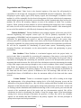
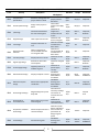
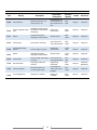
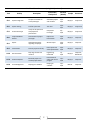
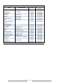
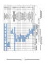
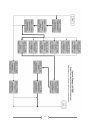
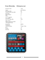
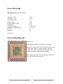
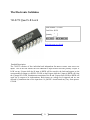
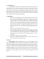
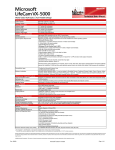
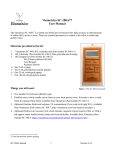
HARDING UNIVERSITY
Single Player Against
Machine BAttleship Game
System Design and Project Plan
Matt Goodhart
Timothy Hoffmann
Matt Lewis
Tatiana Zeledon
Table of Contents
System Design ............................................................................................. 3
Background ....................................................................................... 4
System Overview ............................................................................... 4
Block Diagram .................................................................................. 6
Functional Description of Blocks ..................................................... 7
Project Plan ............................................................................................... 11
Organization and Management ..................................................... 12
Work Breakdown Structure – Fall 2009........................................ 13
Work Breakdown Structure – Spring 2010 ................................... 15
Estimated Costs ............................................................................... 18
Gantt Chart – Fall 2009 .................................................................. 19
Gantt Chart – Spring 2010 ............................................................. 20
Network Diagram – Fall 2009 ........................................................ 21
Network Diagram – Spring 2010.................................................... 22
Appendices ................................................................................................ 23
Appendix A – Budget References ................................................... 24
Appendix B – Requirements Specification .................................... 33
2
System Design
3
Background
Battleship® is a very popular game around the world whose origin dates back to the early
1900’s when it was invented by Clifford Von Wickler. However, he never patented the game and
it was trademarked and commercially produced by the Milton Bradley Company in 1943 as a
paper and pencil game. By the 1960’s, and perhaps earlier, a player was able to purchase
prepared paper sheets for the game. Since the beginning, letters were printed in the outer vertical
edges of the sheet and numbers were printed horizontally at the top.
In 1967, the board game of Battleship® was created. The pencil and paper were
discarded and were replaced with plastic ships, pegs, and trays. Later, in 1983, the Milton
Bradley Company improved the version and included electronic components and new features
such as lights and sound. In 2008, the latest version of Battleship® called ‘The Tactical Combat’
was introduced and it includes several modifications to the existing version such as the shape of
the ships and board. The Milton Bradley Company has being the only company to continuously
produce a Battleship® game for any extended period of time.
Our motivation is to create a technically challenging, semi-automated version of the
game Battleship® in order to promote the interest of future Harding students into the engineering
program.
System Overview
Our goal is to create an essentially hands-free version of the classic Battleship® game.
The game will be powered through a standard 110 V AC household outlet. There will be a
keypad that will receive input such as accepting the coordinates of the player’s moves. Also,
there will be an LCD screen that will provide feedback to the user and will prompt the user with
instructions and notifications, such as when to make a move or indicate when the player has sunk
one of the computer’s ships.
Beginning game play will require the player to physically place his/her ship pieces on the
lower display board. The player then indicates to the computer that this has been done, and the
game begins a random selection of who (player or computer) goes first. This selection will be
indicated on the LCD screen. On his/her turn, the player inputs his/her move. The
microprocessor then discerns if the input was a hit or miss and gives the corresponding output on
4
the upper display. Outputs include lighting a red LED (hit) or a green LED (miss). On the
computer’s turn, a plunger/button system moves and senses whether there is a ship in that
coordinate or not, and shows its output on the lower display by placing a red (hit) or green (miss)
ball via the ball manipulator into the selected spot.
This process is repeated until the computer determines that all the player’s ships have
been sunk or all the computer’s ships have been sunk. Whenever one of these two scenarios
takes place, the game is over. At this point, the user will see where the computer’s ships were as
indicated by red LED’s on the upper display of the board. Results will be displayed until the
on/off switch is pushed. Our prototype will be delivered as a fully functional battleship game.
The top half may be closed and latched so that it may be transported.
5
Block Diagram
Single Player Against Machine BAttleship Game
Matt Goodhart, Timothy Hoffmann, Matt Lewis, Tatiana Zeledon
6
Functional Description of Blocks
Module
I/0 System
Inputs
Power 5V DC and 25mA – Keypad
Power 5V DC and 25mA – LCD for power
Power 1V DC and 25mA – LCD for contrast
User Input
Digital signal to LCD from microcontroller – 0 or 5V DC and 0 or 25mA
Outputs
LCD text
Digital signal from keypad to microcontroller – 0 or 5V DC and 0 or 25mA
Functionality
The user will place his/her move by inputting it on the keypad that looks
similar to the keypad on a phone. The numbers A-J will correspond to the
numbers 1-10 such that 1=A, 2=B, etc. Each button will have both the
number and letter printed on it. The computer will prompt the user to select
a letter and the user will input a letter. The computer will then prompt the
user to select a number and the user will input a number. Those two signals
will be sent to the microcontroller as the user’s move. The LCD screen is
the microcontroller’s way of talking to the user and telling him/her what to
do.
Module
Power Supply
Inputs
Power 110V AC Grounded
Outputs
To keypad – 5V DC and 25mA
To LCD – 1V DC and 25mA
To LCD – 5V DC and 25mA
To microprocessor – 5V DC and 25mA
To 3 motor system – 6V DC and 800mA
To electromagnet controller circuit – 12V DC and 1A
To ship sensor – 5V DC and 25mA
To digital logic – 12V DC and 2.5A
Functionality
The power supply system receives 110V AC from the wall. It then steps
down and cleans up the power before it sends it out to the appropriate
module.
7
Module
3 Motor System
Inputs
Power 6V DC and 800mA
Signal to motor from microcontroller – 0 or 5V DC and 0 or 25mA
Outputs
Movement
Functionality
Each of the three stepper motors is responsible for moving a part of the game
in a certain direction. There are three motors: the letters motor, the numbers
motor, and the plunger motor. Each motor receives power from the power
supply and moves as long as power is received as determined by the
microcontroller. The letters motor causes the ball manipulator and plunger to
move parallel to the letters. The numbers motor has the same function as the
letters motor except it moves parallel to the numbers. The plunger motor is
what causes the push button to raise and lower to test of the presence of a
ship.
Module
Electromagnet Controller Circuit
Inputs
Power 12V DC and 1A
Digital signal from microcontroller – 0 or 5V DC and 0 or 25mA
Outputs
0 or 12V DC and 0 or 1A
Functionality
Accepts a digital signal from the microcontroller which tells the circuit
whether or not to allow power to the electromagnet.
Module
Electromagnet
Inputs
Power 12 V DC and 1A
Digital signal to electromagnet from electromagnet controller circuit – 0 or
5V DC and 0 or 25mA
Outputs
Ball Placement
Functionality
When the electromagnet receives power from the electromagnet controller
circuit, it attracts a ball from the ball hopper and carries that ball to the
appropriate location via the motors. When the electromagnet no longer
receives power, the ball drops into the hole corresponding to the computer’s
move.
8
Module
Ship Sensor
Inputs
Power 5V DC and 200mA
Outputs
Digital signal to microcontroller – 0 or 5V DC and 0 or 25mA
Functionality The ship sensor is in the form of a push button. The plunger motor will lower the
button down to approximately halfway between the height of the board and the
height of the ship piece. If a ship is present, the button will be below the level of
the ship and the button will be depressed. It will return a high signal telling the
microcontroller that a ship is present and the guess is a hit. If a ship is not present,
the button will not be depressed. It will continue to return a low signal telling the
microcontroller that the guess is a miss.
Module
Digital Logic
Inputs
Power 0V DC and 5V DC and 200A – for flip-flop
Power 12V DC and 2.5 A
Digital signal from microcontroller – 0 or 5V DC and 0 or 25mA
Outputs
0 to 12V and 0 to 2.5A
Functionality
Accepts signals from the microcontroller and logically determines the necessary
output through a series of multiplexors and latches.
Module
LED Array
Inputs
0 to 12V DC and 0 to 2.5A
Outputs
Lit LEDs
Functionality
The LED array is the physical display the user will see that displays the moves
that he/she has selected. Individual LEDs receive power from the power supply
that has been directed by the digital logic.
9
Module
Microcontroller
Inputs
Power 5 V DC and max of 300mA
Digital signal from I/O System – 0 or 5V DC and 0 or 25mA
Digital signal from push button – 0 or 5V DC and 0 or 25mA
Outputs
Digital signal to I/O System – 0 or 5V DC and 0 or 25mA
Digital signal to 3 motor system – 0 or 5V DC and 0 or 25mA
Digital signal to electromagnet controller circuit – 0 or 5V DC and 0
or 25mA
Digital signal to digital logic – 0 or 5V DC and 0 or 25mA
Functionality
The microcontroller will store and run the program for the battleship
game. This program will keep track of the game progress including
storing previous computer and user moves and will calculate future
moves for the computer accordingly. It will also output signals to the
ball manipulator to place balls indicating the computers moves and
will send signals to the digital logic of the LED system to indicate
user moves. The microcontroller will also send information to the
user via the LCD screen and take in information from the user via the
keypad.
10
Project Plan
11
Organization and Management
Matt Lewis – Matt Lewis is the electrical engineer of the team. He will primarily be
responsible for the design and construction of SPAMBAG’s electrical components. Matt will be
designing the power supply, upper (LED) display, keypad, and electromagnet. In addition to these
modules, he will be responsible for the electrical integration of all parts with electrical components,
which includes powering all electrically powered modules and the communication lines between the
modules. He will be the secondary engineer on most of the modules of which Tim is primary
engineer. While working on these modules, he will be simulating and testing them. After recording
the results, he will use the results from these to better engineer those modules. After mastering how
to test each of the modules, he will effectively demonstrate their performance.
Timothy Hoffmann – Timothy Hoffmann is the computer engineer of the team with a 50/50
electrical engineering and computer science split. He will be primarily responsible for the
programming of SPAMBAG and the integration of the LCD screen to the system. He will also be
responsible for programming the system to send the appropriate signals to the system when
necessary and will be working with Matt Lewis closely on the electrical schematics and design. He
will also be responsible for writing system test programs explained in the requirements specification.
He will also be responsible for contributing to system status reports, documenting progress,
designing flowcharts and schematics on the microcontroller system, and participating in group
presentations.
Matt Goodhart – Matt Goodhart is a mechanical engineer and is the project leader. As
project leader, Matt is responsible for overseeing all components of the project, reviewing all final
documents, keeping the project on schedule, and keeping track of the budget. For the project, Matt is
responsible for designing and constructing the movement system for the ball placement system and
integrating that with the motors. He will do all of the calculations involved in determining the number
of steps each stepper motor must go through to arrive at each coordinate. Matt is jointly responsible
with Tatiana for designing and constructing the frame. He will be the secondary engineer on any
modules on which Tatiana is the primary engineer. He will create CAD drawings in SolidWorks of
the frame and the three motor systems. In addition to the CAD drawings, Matt will also use the
MotionWorks feature of SolidWorks to show the movement ability of the frame and three motor
systems.
Tatiana Zeledon – Tatiana is a mechanical engineer. She will be working in the design
and implementation of the plunger/button sensing device of the ball placement system and the
fabrication of the physical ship pieces. She will also be working with Matt Goodhart in the system
integration of the ball placement system and the design and construction of the frame. Tatiana will
be working with the simulations and SolidWorks drawings of the overall system, parts selection and
research of the mechanical parts of the project and any documentation required. She will do
calculations involved in determining the number of steps the stepper motor of the button/plunger
sensing device must go through to determine the presence of a ship. She will be the secondary
engineer on the modules that Matt Goodhart is the primary engineer. She will also participate in
group written reports and oral presentations.
12
Work Breakdown Structure – Fall 2009
Task
Activity
Deliverable /
Checkpoints
Description
F1.0
Requirements
Specification
Document stating what the
project will do in detail
F2.0
Overall System Design
Design entire project in
detail
F3.0
I/O Design
Communicates between
the user and the game
F3.1
Keypad Design
Takes input from the user
F3.2
LCD Design
Outputs Information to
user
F4.0
Microcontroller
Selection
Select an appropriate
microcontroller that will
run the game code
F5.0
LED Array Design
Displays the user's moves
F6.0
Digital Logic Design
Determines which LEDs
receive power
F7.0
Power Supply Design
Supplies power to all
modules of game
F8.0
Ball Placement Design
Displays computer's moves
F8.1
Movement System
Design
Moves ball to appropriate
coordinates
F8.2
Electromagnet Design
Magnetically picks up and
drops ball
F8.3
Electromagnet
Controller Circuit
Allows power to go to the
electromagnet
F8.4
Ship Sensor and Game
Piece Design
Senses the presence of the
constructed ships
F9.0
Frame Design
Encases entire game
13
Basic ideas of
project, written
document
Choose best
solutions and apply
them
Schematic of
keypad and
selection of LCD
screen
Schematic and
sketch of keypad
Selection of LCD &
manufacturer's
data sheets
Selection of
microcontroller &
manufacturer’s
data sheets
Schematic of LED
circuitry
Schematic of digital
logic
Schematic of
power supply
circuitry
SolidWorks
drawings and
MotionWorks
simulations
SolidWorks
drawings and
MotionWorks
simulations
Calculations of
necessary windings
and current &
material size and
shape
Schematic of
electromagnet
controller circuitry
Selection of push
button and idea of
how to lower the
push button &
design of game
pieces
SolidWorks
drawings and
mockups
Duration
People
Resources
9/13 9/29
M,M,T,T
Computer
9/25 10/16
M,M,T,T
Computer
10/15 11/3
Matt L.,
Tim
Computer,
Multisim
10/15 10/30
Matt L.
Computer,
Multisim
10/20 11/3
Tim
Computer
11/3 11/15
Tim
Computer
10/22 11/15
10/22 11/15
Matt L.
Matt L.
Computer,
Multisim
Computer,
Multisim
10/22 –
11/3
Matt L.
Computer,
Multisim
10/15 11/15
M,M,
Tatiana
Computer,
SolidWorks
11/1 11/15
Matt G.
Computer,
SolidWorks
10/20 11/5
Matt L.
Physical
tests
10/20 11/5
Matt L.
Computer,
Multisim
11/08 11/15
Tatiana
Computer
10/15 11/15
Matt G.,
Tatiana
Computer,
SolidWorks
Work Breakdown Structure – Fall 2009 (continued)
Task
Activity
Deliverable /
Checkpoints
Description
Duration
(Weeks)
People
Resources
Documentation of
ordered parts and
data sheets of each
part
9/20 12/8
M,M,T,T
Computer
F10.0
Parts Selection
Make final decision as to
which parts to use
F11.0
System Design & Project
Plan
Breakdown of design and
build process and detailed
scheduling
Report and
Presentation
9/29 10/15
M,M,T,T
Computer
F11.1
Report
Write detailed report
regarding the above ideas
Written report
9/29 10/13
M,M,T,T
Computer
F11.2
Presentation
Present ideas to faculty
Power point and
verbal presentation
10/4 10/15
M,M,T,T
Computer
F12.0
Intermediate Design
Review
Finalize design of project
Report and
Presentation
11/16 12/9
M,M,T,T
Computer
F12.1
Report
Write detailed report
regarding the above ideas
Written report
11/16 12/9
M,M,T,T
Computer
F12.2
Presentation
M,M,T,T
Computer
O1.0
Documentation
M,M,T,T
Computer,
Notebooks
O2.0
A3 Status Reports
Bimonthly reports on
current project status
O3.0
Time Management
Keeping to a schedule
Present design and analysis
to faculty
Keep logs of work and
research
14
Power point and
verbal presentation
Engineering
notebooks
Presentation of
status and current
progress
12/1 12/9
9/13 12/31
9/13 12/10
M,M,T,T
Computer
Keeping on
schedule
9/13 12/10
Matt G.
Computer
Work Breakdown Structure – Spring 2010
Task
Activity
Deliverable /
Checkpoints
Description
Duration
(Weeks)
People
Resources
S1.0
Parts assembly &
Testing
Assemble all parts and
verify they work correctly
Working modules
and test data
1/11 3/21
M,M,T,T
Various
digital and
general tools
S1.1
I/O System
Create and test interface
between user and game
Receives all inputs
and outputs all text
correctly
1/11 2/10
Matt L.,
Tim
ELVIS unit
Keypad
Create and test a keypad
circuit for user input
Working keypad
that accepts all
inputs correctly
1/11 1/25
Matt L.
ELVIS unit
LCD
Connect and test LCD
screen with the
microcontroller
1/20 2/10
Tim
ELVIS unit
S1.2
Microcontroller
Create and test code for
system
1/11 3/21
Tim
Programmer,
Computer
S1.3
LED Array
Create and test LED
circuitry for upper display
1/25 3/10
Matt L.
ELVIS unit
S1.4
Digital Logic
Create and test digital logic
circuitry for upper display
1/25 3/10
Matt L.
ELVIS unit
S1.5
Power Supply
Build and test voltage
control circuit
1/20 2/17
Matt L.
ELVIS unit
M,M,
Tatiana
Machine
equipment,
ELVIS unit,
Computer,
General
tools
S1.1.1
S1.1.2
S1.6
Ball Placement System
Working LCD
screen that
outputs all text
correctly at the
appropriate time
Microcontroller is
integrated with all
other systems
Array of LEDs that
are all visible when
lit in a well-lit room
Circuit that allows
power to go to all
of the right LEDs
Working module
that steps down
the voltage and
current to the
correct values
Build and test device to
place balls
Working module
and test data
1/15 3/21
1/27 3/21
Matt G.
Machine
equipment,
SolidWorks,
General
tools
S1.6.1
Movement System
Build and test the motor
and rail system
System of motors,
gears, and rails
that successfully
translates the drive
train to the correct
location
S1.6.2
Electromagnet
Build and test magnetic
device to pick up and drop
balls
Fully functional
electromagnet
1/15 2/15
Matt L.
ELVIS unit
Electromagnet
Controller Circuit
Create and test
electromagnet controller
circuit
Circuit that allows
power to go to the
electromagnet
when a signal is
received
1/152/15
Matt L.
Elvis unit
S1.6.3
15
Work Breakdown Structure – Spring 2010 (continued)
Task
Activity
Deliverable /
Checkpoints
Description
People
Resources
2/15 3/21
Tatiana
Machine
equipment,
SolidWorks,
General
tools
1/27 3/15
Matt L.,
Tim
Express PCB
Functioning system
code
1/11 4/15
Tim
Programmer,
Computer
Write and test code for the
keypad
Functioning keypad
code
1/11 4/15
Tim
Programmer,
Computer
LCD
Write and test code for
LCD screen
Functioning LCD
screen code
1/11 4/15
Tim
Programmer,
Computer
S2.3
Movement System
Write and test code for
translation motor
movement
Functioning
translation motor
movement code
1/11 4/15
Tim
Programmer,
Computer
S2.4
Plunger Motor
Write and test code for
plunger motor movement
Functioning
plunger motor
code
1/11 4/15
Tim
Programmer,
Computer
S2.5
Push Button
Write and test code for
push button
Functioning push
button code
1/11 4/15
Tim
Programmer,
Computer
S2.6
Electromagnet
Write and test code for the
electromagnet
Functioning
electromagnet
code
1/11 4/15
Tim
Programmer,
Computer
S2.8
LED Output Signals
Write and test code for
turning LEDs on
Functioning LED
output code
1/11 4/15
Tim
Programmer,
Computer
S2.7
Artificial Intelligence
Write and test code for
artificial intelligence
Functioning
artificial
intelligence code
1/11 4/15
Tim
Programmer,
Computer
S3.0
Final Design Review
Presentation of final
design
Report and
Presentation
2/20 3/4
M,M,T,T
Computer
S3.1
Report
Write detailed report
regarding the above ideas
Written report
2/20 3/4
M,M,T,T
Computer
S3.2
Presentation
Present ideas to faculty
Power point and
verbal
presentation
2/20 3/4
M,M,T,T
Computer
S4.0
Build Frame
Construct a frame to
encase the game
components
Completed Frame
2/4 3/20
Matt G.,
Tatiana
Project Lab
Ship Sensor
Build and test Plunger to
sense ship pieces on the
lower display of game
S1.7
Board Etching
Design circuit boards for
final system and etch them
S2.0
Programming
Write and test code for
microcontroller
S2.1
Keypad
S2.2
S1.6.4
16
Five ship pieces
and a push button
that sends a high
signal when
pressed
professionally
made circuit
boards
Duration
(Weeks)
Work Breakdown Structure – Spring 2010 (continued)
Task
Activity
Deliverable /
Checkpoints
Description
Duration
(Weeks)
People
Resources
S5.0
System Integration
Compile all modules to
create prototype
Assembled project
and test data
3/25 4/15
M,M,T,T
Project Lab
S6.0
System Testing
Run full system test
Test data
3/25 4/15
M,M,T,T
Project Lab
S7.0
Finalize Prototype
Verify correct operation
and prepare for
presentation
Completed
Prototype
4/5 4/29
M,M,T,T
Project Lab
S8.0
Project Readiness
Review
Presentation of project
prototype
Report and
Presentation
4/10 4/29
M,M,T,T
Computer
S8.1
Report
Write detailed report
regarding the project
Written report
4/10 4/29
M,M,T,T
Computer
S8.2
Presentation
Present project to faculty
Power point and
verbal presentation
4/10 4/29
M,M,T,T
Computer
O4.0
Documentation
Keep logs of work and
research
Engineering
notebooks
1/1 4/29
M,M,T,T
Computer,
Notebooks
O5.0
A3 Status Reports
Bimonthly reports on
current project status
Presentation of
status and current
progress
1/11 4/29
M,M,T,T
Computer
O6.0
Time Management
Keeping to a schedule
Keeping on
schedule
1/11 4/29
Matt G.
Computer
17
Estimated Cost of Supplies
$20.00
$10.00
$15.00
$8.00
$8.00
$8.00
$20.00
Date of
Estimate
10/12/2009
10/12/2009
10/12/2009
10/12/2009
10/12/2009
10/12/2009
10/12/2009
Professional etching
board
$60.00
10/12/2009
Non-professional
etching boards
Steel balls
Motors
LEDs
Microcontroller
Materials for frame
Movement supplies
Push button
Keypad
LCD screen
Miscellaneous
Total
$30.00
10/12/2009
$33.00
$70.00
$30.00
$50.00
$200.00
$50.00
$5.00
$20.00
$25.00
$188.00
10/5/2009
10/5/2009
10/5/2009
10/5/2009
10/5/2009
10/5/2009
10/5/2009
10/5/2009
10/5/2009
10/5/2009
Item
Latches
Transformers
Multiplexer
Resisters
Diodes
Voltage Regulators
Wire
Possible Vendor
Cost
The Electronic Goldmine
Honeywell
Radio Shack
Radio Shack
Radio Shack
Radio Shack
McMaster-Carr
Robot Shop
Electronix Express
Microchip / Schmartboard
McMaster-Carr
McMaster-Carr
All Electronics Corporation
Crystal Fontz
$850.00
18
19
20
21
22
Appendices
23
Appendix A – Budget References
24
McMaster-Carr
Steel
This product matches all of your selections.
Part Number: 9528K24
$14.01 per Pack of 100
Material
Bearing-Quality Aircraft-Grade E52100 Alloy Steel
Alloy
E52100
Shape
Balls
Diameter
1/2"
Diameter
±.0001"
Tolerance
Tolerance
Standard
Temper/Condition Hardened, Quenched, Tempered
Hardness
Rockwell C60-C67
Yield Strength
295,000 psi
Grade
25
Specifications Met American Society for Testing and Materials (ASTM)
ASTM
ASTM A295
Specification
Hardness and yield strength are not guaranteed and are
WARNING
intended only as a basis for comparison.
2 Packs of 100 for a total of $33.77.
25
From Robot Shop USA
Soyo 6V 0.8A 36oz-in Unipolar Stepper Motor
Price for one: $19.99. We bought 3 for a total of $66.09.
Soyo SY42STH38-0806A Unipolar Stepper Motor
• Voltage: 6vdc
• Resolution of 1.8 degrees/step
• Torque of 36 oz/inch
• Precision of ±5%
Professional and very high precision stepper motor. An even higher precision can be achieved
(0.9 degrees/step) by using "half step mode" on the Active Robots Easy-Step 3000 stepper motor
controller (RB-Act-01, RB-Act-02, RB-Act-03, RB-Act-04, RB-Act-06).
26
Electronix Express
Dual Color LED
Part No.
Description
08LEG3392
Red/Green
08LYG3392
Yellow/Green
08L3015EGW
Red/Green
08L3015YGW
Yellow/Green
·
·
·
·
·
·
·
·
·
Size
5mm
5mm
3mm
3mm
1-9
$0.25
$0.25
$0.25
$0.25
10+
$0.20
$0.20
$0.20
$0.20
White diffuse lens.
Two different colors depending on leads used (Red or Green)
170 degree viewing angle.
25 mA
10 mCa
5 mm diameter
part no. 08LEG3392
price: $0.20 per LED (If purchasing 10 or more)
Website: http://www.elexp.com/opt_3392.htm
27
From Microchip
Parameter Name
Family
Max Speed MHz
Program Memory Size (KB)
RAM (KB)
DMA Channels
SPITM
I2CTM Compatible
A/D channels
Max A/D Sample Rate
Input Capture
Output Compare/Std. PWM
16-bit Digital Timers
Parallel Port
Comparators
Internal Oscillator
RTCC
I/O Pins
Pin Count
- Microprocessor
Value
PIC32MX4xx
80
128
32
4
2
2
16
1000
5
5
5
PMP16
2
8 MHz, 32 kHz
Yes
85
100
28
From Microchip
Microprocessor # dsPIC30F6015
Parameter Name
Architecture
CPU Speed (MIPS)
Memory Type
Program Memory (KB)
RAM Bytes
Temperature Range
Operating Voltage Range (V)
I/O Pins
Pin Count
Value
16-bit
30
Flash
144
8,192
C -40 to 125
2.5 to 5.5
52
64
Cost: $9.94
From SchmartBoards
202-0014-01
SchmartBoard|ez QFP 64-100 Pins, 0.4mm Pitch
Support 64-100 pins QFP, TQFP, PQFP package IC with
0.4mm pitch, 20 pieces of 0603 package, and some
though-hole passive components. 6 ground holes are
connected a copper plane on the bottom side.
This product utilizes the "EZ" technology to assure fast,
easy, and flawless hand soldering
29
From All Electronics Corporation
SPDT MOM. PUSHBUTTON, PC MOUNT
CAT# PB-157
Apem # TP32, Miniature S.P.D.T momentary pushbutton switch. Right-angle, vertical pc mounting.
Removeable 0.2” diameter black cap. 5mm diameter, flatted plain bushing. Single pc mounting pin o
front of switch body. Rated 0.4 VA 20V max.
Cost: $0.40
From Crystalfontz
CFAH1602D-YTI-ET
Parallel Character LCD 16x2, RoHS Compliant, Yellow/Green LED Backlight, FSTN Negative,
Transmissive -20°C - +70°C 6:00
Cost: $25.00
30
The Electronic Goldmine
74LS279 Quad S-R Latch
Item Number : G12600
Unit Price: $0.29
Quantity
1
Refer this page to a friend
Detailed Description
The 74LS279 consists of four individual and independent Set-Reset Latches with active low
inputs. Two of the four latches have an additional S input ANDed with the primary S input. A
LOW on any S input while the R input is HIGH will be stored in the latch and appear on the
corresponding Q output as a HIGH. A LOW on the R input while the S input is HIGH will clear
the Q output to a LOW. Simultaneous transition of the R and S inputs from LOW-to-HIGH will
cause the Q output to be indeterminate. Both inputs are voltage level triggered and are not
affected by transition time of the input data. 16 pin DIP. Actual brand may vary from picture.
G12600
31
Found at Amazon.com
Honeywell RCA900N1008/A 16V Low
Voltage Transformer
Other products by Honeywell
No customer reviews yet. Be the first.
List
Price:
$11.99
Price:
$10.61 & eligible for FREE Super Saver Shipping on orders over $25 or FREE
Two-Day Shipping on orders of any size with a free trial of Amazon Prime. Details
You
Save:
$1.38 (12%)
32
Appendix B – Requirements Specification
33
Single Player Against Machine BAttleship Game
(SPAMBAG)
Requirements Specification
Matt Goodhart, Timothy Hoffmann, Matt Lewis, Tatiana Zeledon
OVERVIEW:
Battleship is a classic game that many people play in their childhood.
Typically, it is a two player game where one person plays against another. We are
recreating this game so that one person can play by themselves against an interactive
computer that has a robotic piece placement device. This allows a novice player to get a
feel for the rules and potentially develop and improve strategies of their own. Aside from
the inputs from the player on where he/she wants to place his/her ships and target the
computer’s ships, the game is hands free.
OPERATIONAL DESCRIPTION:
Our battleship game will follow all of the standard rules of the classic battleship
game. There will be a user input-interface, most likely an interactive LCD screen that will
prompt the user with instructions and notifications, such as when to make a move or
indicate when the player sunk one of the computer’s ships. There will also be a keypad
which will accept the coordinates of the player’s moves. Beginning game play will
require the player to physically place his/her ship pieces on the lower display. Once the
player’s ships have been placed, the game begins a random selection of who (player or
computer) goes first. This selection will be indicated on the LCD screen. On his/her turn,
the player inputs his/her move. The microprocessor then discerns if the input was a hit or
miss and gives the corresponding output on the upper display. Outputs include lighting a
red LED (hit) or a green LED (miss). On the computer’s turn, it makes a move, the
microprocessor discerns a hit or miss, and shows its output on the lower display by
placing a red (hit) or green (miss) ball via the ball manipulator into its respective spot.
This process is repeated until the game is over.
DELIVERABLES:
· User’s Manual
· Software Logic Flowchart
· Technical Drawings and Analysis of Hardware
· Schematic of Circuit with Simulation Results
· Documentation of Testing
· A Final Report
· Parts List with Budget
· Battleship Game
34
DRAFT USER MANUAL:
Setup:
· Remove the game from its package
· Open the lid for the game
· Plug in the power cord to a Type B NEMA 5-15 15 A/125 V grounded
outlet.
· Separate the balls by color and load them into the containers.
· Turn on the game by flipping the ON/OFF switch located on the board.
Operation:
1. Physically place the ship pieces on the lower display board so that the holes in
the piece correspond to holes in the board.
· For the aircraft carrier (five cells).
· For the battleship (four cells).
· For the cruiser (three cells).
· For the submarine (three cells).
· For the destroyer (two cells).
2. Wait for the computer to choose the location of its ships as indicated by the
LCD screen located in the upper display of the game.
3. If the LCD screen indicates that it is the player’s turn, select coordinate of
attack (a space on the grid you believe the computer’s ship is). If the LCD
screen indicates that it is the computer’s turn, continue to step six (beginning
of game only).
4. Enter the coordinate on the keypad by selecting the letter (A-J) that
corresponds to the chosen location and then select a number (1-10) that
corresponds to the same location.
5. Notice the LED light up which indicate that the coordinate selected in step 3
was either a hit (red) or a miss (green).
6. Wait for the computer’s turn.
7. The attack of the computer will be recorded by dropping a ball on the lower
display. The ball will be red if it coincides with the location of one of your
ships; it will be green if it is a miss.
8. Repeat steps three through seven until the game is completed as indicated by
the LCD screen.
9. Select the option to play a new game if desired and repeat steps one through
eight or turn off the device using the ON/OFF switch on the lower display.
10. Unplug the game from the outlet.
35
USER INTERFACE:
The user interface will consist of an ON/OFF switch that allows the system to be
turned on and off. There will also be ship pieces for the user to physically place on the
lower display board to indicate the location of the user’s ships. There will be a keypad
that will act as an input receiver for the user’s moves and will also have keys for the
player to indicate if the computer sunk a ship. Also included is an interactive LCD screen
that will prompt the user when it is their turn, whether they hit or missed the computer’s
ship, and other instructions throughout the gameplay.
CAPABILITIES:
· Will have artificial intelligence for the computer to choose locations close to a
hit in order to sink the user’s ship. Once two hits are found, only locations
along a straight line should be attempted until a sinking takes place as
confirmed by the user via the keypad. When the user indicates which ship has
been sunk via the keypad, the computer will determine if it hit another ship in
the process. If so, the computer will continue selecting coordinates in the area
until it sinks that ship. Once the computer determines that there are no more
known ships in the area, it will continue selecting random coordinates of
attack.
· Will be able to be operated and moved by one person.
· Will acknowledge whether the coordinate selected corresponds to either a hit
or a miss by displaying a message in the LCD screen and lighting up the LED
in the upper display of the game that corresponds to the coordinated selected
by the user. If it is a hit the color of the LED will be red and if it is a miss it
will be green.
· Will be able to setup in no more than 5 minutes.
· Will be able to place balls of different colors to different locations on the
board in no more than 20 seconds per move.
TESTING:
Ball Manipulator Test / Motor Test: To test the ball manipulator and the
motors, a full mechanical system test will be performed where a test program is run and
tells the ball manipulator to place one ball in every possible location (A1-A10 though J1J10) in order. The test will be considered successful if the mechanical device arrives at
the correct coordinate every time and if the ball makes it to the coordinate without
dropping prematurely 99 out of 100 times the movement is done. This test will be run
five times and statistical analysis will be performed on the results. If the ball drops
prematurely, the user can place the ball in the correct location as displayed on the LCD
screen.
36
Portability test: To determine portability and ease of operation by one person,
three volunteers not associated with the Senior Design class will move the device to a
testing room where outlets are available and will follow the setup and operation as
described in the user’s manual. Feedback will be gathered from the volunteers via a
survey to determine if the device is portable and through observation if it is easily
operated. The game will weigh no more than 22.73 kg (50 pounds) and will take up a
volume no more than 1.0 m3. The footprint of the device will be no more than 1.0 m2 and
its depth no greater than 1.0 m.
LEDs Test: To test the proper functioning of the LEDs, the program will be
written so that every possible location corresponds to a hit. Then, a tester will key in
values for all one hundred locations. The program will reset the board and repeat the
process so that all locations correspond to a miss. Only one LED must be lit whenever a
coordinate is entered and should be either green (miss) or red (hit). If only one LED
lights up for each entry and corresponds to the correct color, the LED test will be
considered a success. Also, there will be a question on the survey for the volunteers that
asks how easily the LEDs were seen.
Artificial Intelligence Test: To test the artificial intelligence of the computer,
following a hit, it must continue choosing coordinates in the immediate proximity of the
hit. Once two hits are found, only locations along a straight line should be attempted until
a confirmed sinking takes place. Also, if it is known that a particular ship has been sunk,
the computer will not attempt to re-sink that battleship. Once sunk, the computer may
choose a random location of attack based on an externally programmed algorithm. The
AI will be tested by playing the game.
37