1
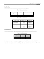
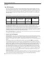
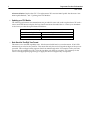
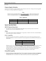
October 22, 1998
GFK-1059B
IMPORTANT PRODUCT INFORMATION
READ THIS INFORMATION FIRST
Product:
Programmable Controller CPU Modules
IC697CPU788-DA / IC697CPU788-EA [
IC697CPU789-DA / IC697CPU789-EA [
Important: These products have tested “Year 2000 capability affected.” It is
strongly recommended that you read the Year 2000 information contained in
this document.
Introduction
This document contains information not available in any other publication; therefore, we recommend you
keep it for future reference. This document covers two subjects: (1) Year 2000 remediation workarounds,
covered in the “Year 2000 Information” section, and (2) information about the IC697CPU788 and
IC697CPU789 CPU modules and firmware release 5.01. These CPU modules are used in IC66* (IC660 or
IC661) Modular Redundancy Systems (GMR) systems. The purpose of firmware release 5.01 is to support
Phase II of the GMR system. Also, several of the features provided in release 5.00 of the standard IC697 CPU
modules are also made available in the GMR CPUs (Sequential Function Chart user programs, Parameterized
Subroutines, and other new features described under ”New Features and Functionality”). Release 5.01 of the
GMR CPUs also fixes problems described under ”Problems Resolved by Firmware Release 5.01.”
Table 1. Catalog Numbers
New Catalog Number
Replaces
IC697CPU788-DA
IC697CPU788D
IC697CPU789-DA
IC697CPU789D
Packaging Note
Effective with this product release, the product manual will no longer be shipped in the box with every product.
Product manuals are provided in a library (which is a complete set of manuals) with IC641 programming
software products, are available on CD ROM, or are available as individual manuals.
[
These catalog numbers have CE Mark approval.
2
Important Product Information
GFK-1059B
Identification
Hardware and software identification is summarized in the following tables.
Table 2. Hardware Identification
Catalog Number
Board
Identification
IC697CPU788-DA
CPHA2
44A731786-G01 R07 or later
IC697CPU789-DA
CPHA2
44A731786-G01 R07 or later
Board Revision
Table 3. Firmware Identification
Catalog Number
IC697CPU788-DA
IC697CPU789-DA
EPROM Location
EPROM Label
U72
U73
U74
U75
397-017C 5.01
397-018C 5.01
397-020C 5.01
397-019C 5.01
U72
U73
U74
U75
397-021C 5.01
397-022C 5.01
397-024C 5.01
397-023C 5.01
Documentation
The following table lists the applicable documentation for the IC697CPU788 and IC697CPU789 CPUs.
Table 4. User Documentation
Catalog Number
Data Sheet
User Manual
IC697CPU788-DA
GFK-0806A
see below
IC697CPU789-DA
GFK-0807A
see below
Read this document before installing or attempting to use the IC697CPU788 or IC697CPU789 PLC CPU
Module. For more information, refer to the applicable Programmable Controller Installation Manual, Programming
Software User’s Manual, Programmable Controller Reference Manual, and GMR User’s Manual
Important Product Information
3
GFK-1059B
Year 2000 Information
One issue, causing these two CPUs to test Year 2000 capability affected, has been identified. This issue
does not affect all users of these CPUs. Please read item 1 below to determine if it applies to you. Note
that two solutions are offered for this issue. One is a suggested “workaround” that provides guidance on
how to prevent this issue from affecting your application. The alternative suggestion is to replace your
CPU with a newer model that doesn’t display this characteristic. For that solution, a list of replacement
CPUs is provided.
Versions Tested: The following table identifies the CPU firmware versions tested for Year 2000 capability.
CPU Firmware Versions Tested for Year 2000 Capability
Series 90-70
CPU
Versions Y2K
Capable
As Defined
Below
Versions
Containing Y2K
Leap Year Issue
Versions
Containing Y2K
SVC#7 Write to
TOD
Versions Not
Tested
CPU788
DA/EA (5.01) and earlier
D (4.16) and earlier
CPU789
DA/EA (5.01) and earlier
D (4.16) and earlier
“Year 2000 Capable” Defined: For the solutions that are stated to be “Year 2000 Capable” in the
paragraphs below, that term is defined to mean that (1) the Product’s functionality will not be materially
adversely affected as a result of the date change from 1999 to 2000, including leap year calculations,
provided that all products used with the Product function properly, including without limitation, properly
exchanging accurate date data with the Product; and (2) to the extent applicable to the Product’s normal
operating specifications and subject to any upper and lower limits.
Note on Year Date Format: As a separate item, a note is included at the end of this section explaining the
two-digit year date format for the IC697 CPUs.
1.
Incorrect Leap Year Management
Possible Problem: These CPUs do not manage leap years properly. It has been observed that years that
should be leap years sometimes have only 28 days in February, and years that are not leap years may have
29 days in February. This is only a problem to users who are using this date information in their
application. For example, some use the PLC’s date information to time events or for dating messages and
reports.
R
Observing this condition on the TIME-OF-DAY CLOCK screen of the MS-DOS PLC programming
software package may produce inaccurate results. The programming software (running on a personal
computer) requests the date from the PLC initially, then maintains its own version of the PLC date (based
on the personal computer’s time clock) until either (1) communications with the PLC are lost, or (2) a
different screen is displayed. Therefore, if you were observing the date change at midnight of February 28
using the programming software, you would be observing the programming software’s version of the
date. With the passing of midnight, you would need to exit the TIME-OF-DAY CLOCK screen, then go
back to that screen to cause the programming software to request the time and date from the PLC again.
R
This is not a characteristic of the Windows PLC programming software. It displays the actual PLC time
and date in its Target Comm (Data tab) window because it requests this information from the PLC and
updates this window once each second.
Workaround Solution: To avoid this inaccurate date condition, you can check and reset the PLC’s date (if
it’s not correct) on the day following the February 28 date of each year. Application of this workaround
solution will make the Product Year 2000 Capable. See the item “Year 2000 Capable Defined.”
RMS-DOS and Windows are registered trademarks of Microsoft Corporation.
4
Important Product Information
GFK-1059B
Alternate Solution: Replace the CPU. The replacement CPUs are Year 2000 Capable. See the items “Year
2000 Capable Defined,” and “Updating Your CPU Module.”
2.
Updating your CPU Module
The following replacement recommendations are provided for users who wish to replace their CPU with a
newer model that does not display the Leap Year characteristic described above. Contact your distributor
or the factory to order the replacements listed below.
CPU Replacement Recommendations
3.
CPU to be Replaced
Replacement CPU
IC697CPU788
IC697CPM790
IC697CPU789
IC697CPM790
Note About the Two-Digit Year Format
This item is not a Year 2000 capability issue. It has been included here for your information. IC697 CPUs
maintain a byte value for the year date. This means that only the two least significant digits of the year are
provided. This two-digit format supports dates from 1980 through 2079. For example, for the year 1998,
only the 98 is provided by the CPU; or for the year 2001, only the 01 is provided. It is customary for the
user to create appropriate program logic to supply the other two digits if they are required.
Important Product Information
5
GFK-1059B
Firmware Upgrade Information
Upgrade kits are available to upgrade GMR PLC CPUs to firmware version 5.01. Existing units may be upgraded
for a charge by ordering the applicable field upgrade kit.
Note
Firmware version 5.01 of these CPUs is not “Year 2000 Capable.” Please refer to the previous
section, “Year 2000 Information,” for details on identifying the problem and its remediation.
Table 5. Upgrade Kits
Upgrade Kit
For Upgrading
To
44A731244-G02
IC697CPU788D
IC697CPU788-DA
44A731245-G02
IC697CPU789D
IC697CPU789-DA
Special Operation Notes
GMR CPU Expansion Memory Board
1.
The release 5.01 IC697 CPU models 788 and 789 (GMR CPUs) should only be used with the IC697
expansion memory board IC697MEM735D, or later.
C Blocks
2.
When using C blocks with CPU model 788, the C Programmer ’s Toolkit for IC697 PLCs, IC641SWP709B, or
later must be used to create the C Blocks(s).
IC641 Compatibility
3.
This release of the PLC CPU modules is compatible with the versions of IC641 programming software
listed in the table below. However, version 5.01 or later is required to access all of the CPU’s features and
functionality.
CPU Model
IC641 Programming Software
788
Version 4.02 or later
789
Version 4.02 or later
If Release 5.01 PLC CPU firmware is used with IC641 programming software Release 4.02, the PLC Sweep
Control and Monitor screen (F3 F8) should ONLY be used to change (tune) the constant window or
constant sweep time. Any other use may result in the background window time being incorrectly set to
255 milliseconds. For this IC641 programming software release used with a Release 5.01 CPU, the
configuration package must be used to set the desired sweep modes or window times.
PCM and BTM Compatibility
4.
With the introduction of timing improvements and new features in release 5.00, it is highly recommended that
systems using PCMs use IC697PCM711J or later. It is also highly recommended that systems using BTMs use
IC697BEM713B or later. Use of boards of an earlier revision may result in lower system performance.
6
Important Product Information
GFK-1059B
Notice to Upgrade GBC Hardware
5.
With the introduction of new features in this release, timings with the IC66* Bus Controllers (GBCs/NBCs)
have changed; this has uncovered a problem in the GBC/NBC firmware. GBCs/NBCs in expanded racks
could be lost if the system is fully configured and only the main rack cycles power.
Also, in previous versions of the GBC/NBC there was a problem with input data coherency. In a
system with a large CPU sweep time and a short IC66* bus scan time a problem could be seen if
a device was lost. Input data could be defaulted off while the CPU is reading data from the
GBC/NBC.
It is recommended to update existing GBC/NBC hardware with Bus Controller IC697BEM731M or later when updating PLC CPU firmware to release 5.01.
Foreign VME Modules
6.
IC641 programming software Release 5.00 allows foreign VME modules to be configured for five modes: BUS
INTERFACE, INTERRUPT ONLY, FULL MAIL, I/O SCAN, and REDUCED MAIL. However, the IC697 CPU
Release 5.01 and earlier supports only the BUS INTERFACE mode. The other modes should not be configured.
Maximum PLC Sweep
7.
In systems configured for IC66* Bus Redundancy a complete PLC sweep must be executed every 500 ms
or less, even though it is possible to configure the watchdog timer to higher limits. This also means that
resetting of the watchdog timer with Service Request #8 cannot be done indefinitely.
Serial Communications
8.
The following operational restrictions exist for the Serial Communications feature:
1.
Serial communications may add up to 5 ms of time to any given sweep. This should be taken into account when setting the watchdog timer.
2.
The following procedure is recommended when changing baud rates in the PLC and the WSI board.
First enter the configuration package and change the baud rate on the PLC, then store the new configuration. Now power off the PLC and then go to the WSI setup screen and change the WSI baud rate.
Finally, power the PLC back on.
3.
The link idle time setting in IC641 programming software Config for Serial Communications should
be set to 10 seconds or greater. Otherwise a communications failure will occur when storing the config to the PLC.
Serial Port Mode Configuration
9.
There is a serial port configuration parameter under software configuration for the PLC called MODE.
This configuration parameter can be one of two values: SNP to indicate that the serial port will be used for
SNP communications, or MSG to indicate that the serial port will be used to send printf commands from a
C program block to the connected device. If you have configured MODE to be MSG and are also using
serial IC641 programming software as a means of communicating with the PLC, communications with
IC641 programming software is lost when going to the RUN mode, since the serial port is currently
configured for printf commands from C program blocks.
IC641/WSI Attach
10. Do not connect or disconnect the WSI/BTM cable while the programmer host is powered-on. This action
may cause a running PLC to Stop.
Important Product Information
GFK-1059B
Expansion Rack ID
11. The expansion racks for the IC641 PLC are shipped with the rack ID strapped for rack 0 (the main rack). If
the rack jumper is not changed the PLC will not recognize the rack at all and may not properly identify
the error.
Expansion Rack Cable
12. Do not connect or disconnect the expansion rack cable while the CPU is running. This will cause the PLC
to go to the STOP/HALT mode.
Expansion Rack Power
13. Expansion racks should be powered up at the same time that the main rack is powered up, or they should
be powered up after the main rack has completed its power-up initialization. Do not power-up an expansion
rack while the CPU is running power-up diagnostics.
Memor y Usage
14. A general rule-of-thumb for memory usage is 48 bytes per I/O point plus register memory in bytes.
Timer Operation
15. Care should be taken when timers (ONDTR, TMR, and OFDTR) are used in program blocks that are NOT
called every sweep. The timers accumulate time across calls to the sub-block unless they are reset. This
means that they function like timers operating in a program with a much slower sweep than the timers in
the main program block. For program blocks that are inactive for large periods of time, the timers should
be programmed to account for this catch up feature.
Similar to this are timers that are skipped because of the use of the JUMP instruction. Timers that are
skipped will NOT catch up and will therefore not accumulate time in the same manner as if they were
executed every sweep..
I/O Link Interface
16. When powering up the PLC CPU without a battery and I/O Link Interface boards are present, an incorrect
Loss of Module fault will be logged for each I/O Link Interface board; but the PLC CPU will not consider
these boards as lost, and the boards will continue to operate properly.
Constant Sweep
17. Constant Sweep time, when used, should be set to about 10 ms greater than the normal sweep time to
avoid any oversweep conditions when monitoring or performing on-line changes with the programmer.
The smallest valid constant sweep time setting is 10 milliseconds for the Model 788 and 789 CPUs. Window completion faults will occur if the constant sweep setting is not high enough.
External Devices Writing to CPU Memory
18. At CPU power-up, both the model 788 and 789 CPUs prohibit external devices (PCMs, Ethernet boards,
CMMs, etc.) from having write access into PLC memory (config data, program code, %R, %P, %L, %Q,
%AI, %AQ, %T, %M, %G (including %GA through %GE)). The only devices that are permitted write
access are: parallel IC641 programming software, anything via the built-in serial port, and IC66* Bus
Controllers (GBC/NBCs). If external devices require write access to portions of memory, these areas which
can be written to can be made available by the application using Service Request #31.
7
8
Important Product Information
GFK-1059B
This new Service Request (#31) permits a range within each memory reference type to be
defined as writable by external devices. Service Request #31 does not require that every
memory reference type have a writable area, but does limit the writable area to a single,
contiguous range in each memory reference type specified.
Interaction of IC641 Programming Software with Closed Programming Window
19. The IC641 programming software Sweep Control and Monitor screen cannot be used to change the PLC
Sweep Modes or timers (Constant Sweep Time, Program Window Times, etc.) while the program window
is closed. Use Service Requests #1 through #4 to perform these functions.
Caution
IC641 programming software cannot be used to change the PLC mode (STOP, RUN, etc.) while
the programming window is closed. Use the toggle switch on the CPU module instead.
Problems Resolved by Firmware Release 5.01
1.
If the CPU’s toggle switch was moved to STOP and back to RUN while a C block was sending text out the
serial port, the serial port used to stop working and the CPU had to be power cycled to make SNP and C
block messages work again. This no longer happens: the serial port should continue to work.
2.
When power is cycled on an expansion rack in a system that is running a large sweep time when IC641
programming software is not connected, GBCs/NBCs in that rack will now configure properly.
3.
The COM_REQ function incorrectly allowed the value of the TASK parameter to be greater than 127.
When a TASK value greater than 127 was specified, an incorrect TASK value was sent to the device
specified by the SYSID parameter.
4.
GBC/NBCs could overwrite inputs after passing data to the CPU. This would occur when a device on the
IC66* bus stopped sending data but continued to send a token. Examples of these devices are any device
providing global data or IC670 blocks. This problem requires corresponding fixes in both the IC697 CPU
and the IC697 GBC/NBC modules. Release 5.01 of CPU models 788 and 789 have the CPU fix. All IC697
GBC/NBC modules having catalog number IC697BEM731L, or later, have the corresponding GBC/NBC fix.
New features and Functionality Provided by Firmware Release 5.01
Sequential Function Chart
1.
Release 5.01 of the PLC CPU together with Release 5 of the IC641 programming software has the ability to
create, load/store, and execute Sequential Function Chart (SFC) user programs. SFC is a method
specifically developed for describing industrial sequential control systems. SFC is a graphic method which
represents the functions of a sequential automated system as a sequence of steps and transitions. Each
step represents commands or actions that are either active or inactive. The flow of control passes from one
step to the next through a conditional transition that is either True (1) or False (0). If the transition
condition is true (1), indicated by setting the transition variable, control passes from the active step, which
becomes inactive, to the next step, which then becomes active.
Parameterized Subroutine Blocks
2.
A Parameterized Subroutine Block (PSB) is an optional user-defined function block, configured with
between zero (o) and seven (7) input/output parameter pairs. A parameterized subroutine enables you to
reuse relay ladder logic within the same program or in multiple programs. Logic that needs to be repeated
Important Product Information
GFK-1059B
can be entered in a parameterized subroutine. Calls would then be made to that subroutine to access the
logic. In this way, total program size is reduced. Dividing a program into smaller subroutines simplifies
programming and reduces the overall amount of logic needed for the program. Release 5.01 of the PLC
CPU together with Release 5 of the IC641 programming software has the ability to create, load/store, and
execute parameterized Subroutine Blocks.
RANGE Function Block
3.
A new RANGE function block has been added, which is used to compare a single input value against two
delimiters to determine whether the input value falls within the range of delimiters. Release 5 of IC641
programming software is required for this feature.
ARRAY RANGE Function Block
4.
A new Array RANGE function block has been added, which is used to compare a single input value
against two arrays of delimiters that specify an upper and lower bound to determine whether the input
value falls within the range specified by the delimiters. Release 5 of IC641 programming software is
required for this feature.
User Memory Parity
5.
Release 5.01 of the PLC CPU models 788 and 789 supports parity on the user and system memory. The
following versions of CPU modules and expansion memory module provide this functionality:
CPU Module
IC697CPU788-DA
IC697CPU789-DA
32-bit Expansion Memory Module (512K bytes)
IC697MEM735D
Background Task Window
6.
There are now PLC diagnostic tests that will run in the Background Task Window. The background Timer
configuration value defaults to zero. If you want the tests to run in the Background Window, then change the
Background Timer to a non-zero value. Also, refer to Additions to the PLC Reference Manual for a description of
SVCREQ #5: Change Background Task Window State and Values.
Restrictions and Open Problems
1.
If an expansion rack powers up while the CPU in the main rack is in the RUN mode, the slot fault contacts
will prematurely indicate that the modules in the expansion rack are not faulted before they complete their
power up.
2.
In a multi-rack system, false LOSS OF RACK faults may occur when the system loses power. If this fault is
configured to be fatal, the system will power-up in STOP mode.
3.
When there is no logic stored in a CPU module the %Q and %M tables will be cleared when the CPU is
placed in RUN mode. In this context no logic stored means that no program had ever been stored or that
the clear function on the IC641 programming software had been used to clear logic and configuration.
4.
When the Bit Sequencer sequences from one step to another, the negative transitional contact that corresponds to the original step is not set. The transition contact for the new step is set and remains set until
the sequencer sequences to the next step. This operation is identical to the operation of the previous versions of the CPU firmware.
9
10
Important Product Information
GFK-1059B
5.
If multiple faults exist in an IC697 PLC remote drop and one of them is corrected, a FAULT contact that
uses the remote drop’s module reference will incorrectly indicate that no faults exist at the remote drop.
6.
User application faults logged for Service Request #21 can only use error codes between 0 and 2047. Use
of any other error codes could cause the PLC to treat the alarms as Remote Scanner alarms.
7.
An IC66* Bus Fault may set the fault condition for the M_rsbmm (r=rack, s=slot, b=bus, mm=SBA of
GBC/NBC) fault and nofault contacts. This fault condition will persist until either the fault tables are
cleared or the GBC’s/NBC’s rack is power-cycled.
8.
An Analog Input Base module and its expander modules may not come online if they are configured in an
expansion rack that is missing when the main rack powers up. Power-up the expansion rack first, then
power-up the main rack.
9.
If the main rack loses power during PLC configuration, analog input base boards (ALG230) in expansion racks
that do not lose power may fail. The failure would occur on the subsequent configuration. PLC configuration
occurs during power up, store of configuration, and reads from Retentive (Flash) Memory. To prevent the failure, tie all racks to a common power source. To correct the failure, power-cycle the expansion racks.
10. The IC697 GDS module does not operate with the release 5.01 model 788 or 789 CPU. It will not correctly
power-up if present in a PLC that uses a release 5.01 model 788 or 789 CPU. Do not use the GDS module in a
PLC that has a release 5.01 model 788 or 789 CPU module.